Table of Contents
Advertisement
Quick Links
Advertisement
Table of Contents

Related Manuals for Phoenix Contact IRT Series


Summary of Contents for Phoenix Contact IRT Series
- Page 1 IRT switch for PROFINET realtime User manual...
- Page 2 FL SWITCH IRT 2TX 2POF 2700691 FL SWITCH IRT TX 3POF 2700692 FL SWITCH IRT 4TX 2700689 FL SWITCH IRT IP TX/3POF 2700697 FL SWITCH IRT IP 4TX 2700694 PHOENIX CONTACT GmbH & Co. KG • Flachsmarktstraße 8 • 32825 Blomberg • Germany phoenixcontact.com...
-
Page 3: Table Of Contents
Cut-through ..................20 4.2.2 Store and forward ................20 4.2.3 Multi-address function ................20 4.2.4 Learning addresses ................20 4.2.5 Prioritization ..................21 Configuration and diagnostics ....................23 Web-based management (WBM)................ 23 5.1.1 General function ................... 23 3 / 52 8289_en_04 PHOENIX CONTACT... - Page 4 PROFINET stack and PDEV function ........... 40 Link Layer Discovery Protocol (LLDP) ..................41 Basics........................41 Topology representation via an engineering tool ..........42 Technical data and ordering data .....................43 Technical data ..................... 43 Ordering data ...................... 47 4 / 52 PHOENIX CONTACT 8289_en_04...
-
Page 5: For Your Safety
Modifications to hardware and firmware of the device are not permitted. Incorrect operation or modifications to the device can endanger your safety or damage the device. Do not repair the device yourself. If the device is defective, please contact Phoenix Contact. 5 / 52 8289_en_04... -
Page 6: Unauthorized Network Access
§§15ff. AktG (German Stock Corporation Act), hereinafter collectively referred to as “Phoenix Contact”, from all third-party claims made due to improper use. For the protection of networks for remote maintenance via VPN, Phoenix Contact offers the mGuard product series security appliances, which you can find described in the latest Phoenix Contact catalog (phoenixcontact.net/products). -
Page 7: Irt Switch For Profinet Realtime
Quick media redundancy Redundancy can also be created with standards: The MRP (Media Redundancy Protocol) ensures safe operation of the entire network even in the event of a cable interrupt. 7 / 52 8289_en_04 PHOENIX CONTACT... - Page 8 Important information is displayed directly on the device. Each port has two or three LEDs. – Signal contact The floating signal contact can be connected here via a 2-pos. COMBICON connector (IP20 versions) or via M12 connectors (IP67 version). 8 / 52 PHOENIX CONTACT 8289_en_04...
-
Page 9: Dimensions Of The Ip20 Switch
Address FAIL 00 A0.45.06.04.02 US1 GND US2 GND R1 R2 Figure 2-3 Housing dimensions of the device in millimeters 2.1.2 Dimensions of the IP67 switch Figure 2-4 Housing dimensions of the device in millimeters 9 / 52 8289_en_04 PHOENIX CONTACT... -
Page 10: Status And Diagnostics Indicators
The system reserve of the optical path is >2 dB (Fiber Optic) Flashing The system reserve of the optical path is between 2 dB and 0 dB 0.5 Hz Diagnostic alarm, system reserve is 0 dB 10 / 52 PHOENIX CONTACT 8289_en_04... -
Page 11: Overview Graphic Of The Ip67 Switch
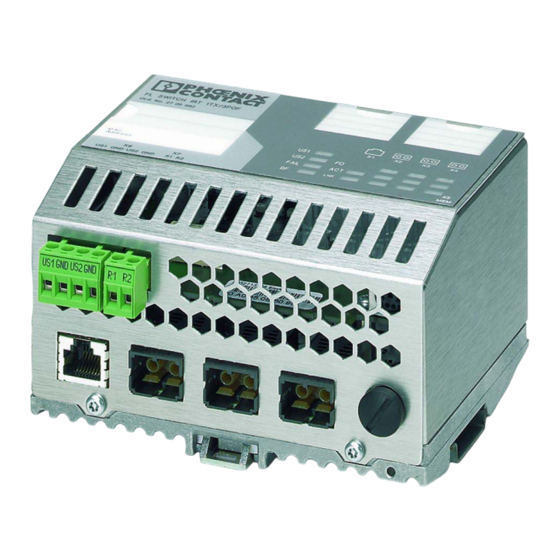
Port labeling fields Device MAC address Diagram of Ethernet Supply port numbering voltage connection Floating Diagnostics/status alarm contact indicators Ethernet ports M12 socket for parameterization memory Figure 2-6 Overview of the IP20 switch 11 / 52 8289_en_04 PHOENIX CONTACT... - Page 12 FL SWITCH IRT 12 / 52 PHOENIX CONTACT 8289_en_04...
-
Page 13: Mounting And Installation
Pull down the positive latch using a suitable tool (e.g., screwdriver). Then swivel the bottom of the module away from the DIN rail slightly (1). Next, lift the module upward away from the DIN rail (2). Figure 3-2 Removing the IRT switch for PROFINET realtime 13 / 52 8289_en_04 PHOENIX CONTACT... -
Page 14: Mounting And Removing The Ip67 Switch
FL SWITCH IRT IP TX/3POF Ord. No. 27 00 697 MAC - Address 00.A0.45.1B.D2.1D FAIL Sno.: 200221439 US1 GND US2 GND PE US1 GND US2 GND PE R1 R2 Figure 3-3 Spacing of the fixing holes 14 / 52 PHOENIX CONTACT 8289_en_04... -
Page 15: Installing The Ip20 Switch
To reset the switch on power up, the power supply must be interrupted for at least three seconds. 3.3.2 Signal contact The switch has a floating signal contact. An error is indicated when the contact is opened. 15 / 52 8289_en_04 PHOENIX CONTACT... -
Page 16: Assignment Of The Rj45 Ethernet Connectors
Assignment of the RJ45 Ethernet connectors Table 3-1 Pin assignment of RJ45 connectors Pin number 10Base-T/10 Mbps 100Base-T/100 Mbps TD+ (transmit) TD+ (transmit) TD- (transmit) TD- (transmit) RD+ (receive) RD+ (receive) RD- (receive) RD- (receive) 16 / 52 PHOENIX CONTACT 8289_en_04... -
Page 17: Installing The Ip67 Switch
A B-coded M12 connector (located on the device) is used to connect the signal contact. Pin 1 and Pin 4 are used for the signal contact. Pins 2, 3 and 5 are not used. Figure 3-8 Pin assignment of the signal contact 17 / 52 8289_en_04 PHOENIX CONTACT... -
Page 18: Grounding
The functional ground of the module is grounded when it is snapped onto the DIN rail. For the IP65 switch, the following requirement must be met: Ensure correct functional grounding of the device, e.g, connecting the ground conductor via the mounting screw or installation on a grounded metallic plate. 18 / 52 PHOENIX CONTACT 8289_en_04... -
Page 19: Startup And Functions
In the case of the IP20 switch, the alarm contact only opens in the event of non-redun- dant power supply. – The aging time is set to 40 seconds. – The switch is in “PROFINET” operating mode. 19 / 52 8289_en_04 PHOENIX CONTACT... -
Page 20: Frame Switching
The FL SWITCH IRT learns addresses and stores them in its table. The switch monitors the age of the learned addresses. The switch automatically deletes address entries from its ad- dress table that have exceeded a specific age (default: 40 seconds). All learned address entries are deleted upon restart. 20 / 52 PHOENIX CONTACT 8289_en_04... -
Page 21: Prioritization
Quality of Service affects the forwarding and handling of data streams and results in individ- ual data streams being treated differently (usually preferential). One possible use of QoS is to guarantee a transmission bandwidth for individual data streams. The switch uses QoS in connection with prioritization (see CoS). 21 / 52 8289_en_04 PHOENIX CONTACT... - Page 22 FL SWITCH IRT 22 / 52 PHOENIX CONTACT 8289_en_04...
-
Page 23: Configuration And Diagnostics
“Configuration Management” web page. The active configuration can be saved permanently by selecting “Save current configuration” on this web page. 5.1.2.1 Structure of the web pages The web pages are divided into four areas: – Device type and device logo 23 / 52 8289_en_04 PHOENIX CONTACT... -
Page 24: Configuration In Wbm
“PROFINET” is activated by default upon delivery. The switch waits for startup by a PROF- INET controller, which also assigns the IP addresses. – The switch is waiting for an IP address assigned by the PROFINET controller. 24 / 52 PHOENIX CONTACT 8289_en_04... - Page 25 The password must be between 8 and 64 characters long. Note that the password is al- ways transferred via the network in unencrypted format. Forgotten your password? Call the Phoenix Contact phone number listed in the Appendix, making sure you have the device serial number and MAC address to hand. “Reboot” menu To trigger a reboot via the web interface, enter a valid password.
- Page 26 The forwarding of PROFINET multicast telegrams can be limited on the “PROFINET Bound- aries” page. By preventing DCP telegrams to be forwarded, the network parts located behind the port can no longer be configured by the requesting controller. 26 / 52 PHOENIX CONTACT 8289_en_04...
- Page 27 This menu provides an overview of the important configuration settings for all ports and also offers the option of setting the status and transmission mode for all existing ports. Figure 5-5 “Port Configuration Table” web page 27 / 52 8289_en_04 PHOENIX CONTACT...
- Page 28 The configuration has been modified but not saved (also indicated by the flashing flop- py disk icon). – Saving the current configuration. – The current configuration is equal to the saved one in the non-volatile memory of the switch. – The current configuration was saved. 28 / 52 PHOENIX CONTACT 8289_en_04...
-
Page 29: Media Redundancy Protocol (Mrp)
“MRP Manager” operating mode is available or accepted in the user interfaces. – If a manager function module is present during the boot process and “MRP Manager” operating mode is activated in the saved switch configuration, the MRP manager func- tion is automatically enabled. 29 / 52 8289_en_04 PHOENIX CONTACT... - Page 30 The “MRP Configuration” web page is used to configure the protocol parameters. The fol- lowing configuration parameters are displayed: – Device role (disabled, MRP client or MRP manager) – Selection of the ring ports that are integrated in the MRP ring 30 / 52 PHOENIX CONTACT 8289_en_04...
- Page 31 Figure 5-12 “Port Redundancy Table” web page Local events On the “Local Events” web page, you can configure which events are to be indicated by the signal contact. 31 / 52 8289_en_04 PHOENIX CONTACT...
-
Page 32: Snmp Configuration
“flWorkFWCtrlConfSave” object. The objects sysName, sysLoca- tion, sysContact of the MIB-II are exceptions to this in PROFINET mode. These objects trig- ger a save operation in PROFINET mode when they are written with a new value. 32 / 52 PHOENIX CONTACT 8289_en_04... - Page 33 (PC) is connected to the destination port, which records the data, yet must not itself be activated. Figure 5-14 “Port Mirroring” web page WBM prevents the same ports from being set, i.e., the source port and destination port must differ. 33 / 52 8289_en_04 PHOENIX CONTACT...
- Page 34 FL SWITCH IRT 34 / 52 PHOENIX CONTACT 8289_en_04...
-
Page 35: Operation As A Profinet Device
You can operate the switch as a PROFINET IO device if you integrate it under a controller in the bus configuration in the engineering tool. A GSD and FDCML file is available for the integration at phoenixcontact.net/products. 35 / 52 8289_en_04 PHOENIX CONTACT... - Page 36 If the device description is available in the device catalog, the following options are available for bus configuration: – Manual - the components are transferred to the bus configuration from the device cat- alog using drag & drop. 36 / 52 PHOENIX CONTACT 8289_en_04...
-
Page 37: Configuring The Switch As A Profinet Io Device
Value = 0 - No active link – Value = 1 - Active link – Value = 3 - Link present, but peer cannot establish link (only for FX ports - Far End Fault Detection) 37 / 52 8289_en_04 PHOENIX CONTACT... -
Page 38: Configuration Via The Engineering Tool
PROFINET alarms The IRT can send the following alarms: – Redundant power supply missing (management agent alarm) All the alarms are deactivated when the device is started. 38 / 52 PHOENIX CONTACT 8289_en_04... -
Page 39: Process Data Communication
- Link status: (0 - Link down; 1 - Link up) - Far end fault status: (0 - No fault; 1 - Fault) - Port enable status: (0 - Enabled; 1 - Disabled) Meaning Port Far end fault Link status enable 39 / 52 8289_en_04 PHOENIX CONTACT... -
Page 40: Pdev Function Description
Link status, port mode, and port MAC address can be requested via the port – Storing of PDEV data – Use of the PN stack LLDP in PN mode (used for neighbor and topology detection) – Support for device replacement and application redundancy – POF diagnostics 40 / 52 PHOENIX CONTACT 8289_en_04... -
Page 41: Link Layer Discovery Protocol (Lldp)
If several neighbors are displayed on one switch port, then at least one other switch/hub that does not support or has not activated LLDP, is installed between this switch and the neighbor indicated. 41 / 52 8289_en_04 PHOENIX CONTACT... -
Page 42: Topology Representation Via An Engineering Tool
FL SWITCH IRT Topology representation via an engineering tool The LLDP information can be represented as such or similarly in engineering tools. Figure 7-1 Topology representation 42 / 52 PHOENIX CONTACT 8289_en_04... -
Page 43: Technical Data And Ordering Data
At 100 Mbps: 148800 pps Supported MIBs MIB II and private SNMP objects from Phoenix Contact Housing dimensions of IP20 switch (width x height x depth) 127 x 95 x 69 (depth from top edge of DIN rail) in mm: Housing dimensions of IP67 switch (width x height x depth) 175.5 x 111.5 x 100... - Page 44 Voltage 24 V DC Current carrying capacity 100 mA Ethernet interfaces Properties of RJ45 ports Number 1, 2 or 4 (version) with autocrossing and auto negotiation Connection format 8-pos. RJ45 socket on the switch 44 / 52 PHOENIX CONTACT 8289_en_04...
- Page 45 Test intensity 3, criterion A Air discharge: Test intensity 3, criterion A Indirect discharge: Noise immunity according to EN 61000-4-3 (IEC 1000-4-3) Requirements according to DIN EN 61000-6-2 (electromagnetic fields) Test intensity 3, criterion A 45 / 52 8289_en_04 PHOENIX CONTACT...
- Page 46 Requirements according to DIN EN 61000-6-2 (conducted) Test intensity 3, criterion A Additional certifications RoHS EEE 2002/95/EC. - WEEE 2002/96/EC Differences between this version and previous versions Rev. 00: initial version Rev. 01: IP67 version integrated 46 / 52 PHOENIX CONTACT 8289_en_04...
-
Page 47: Ordering Data
Patch cable, CAT6, pre-assembled, 1.0 m long FL CAT6 PATCH 1,0 2891385 Patch cable, CAT6, pre-assembled, 1.5 m long FL CAT6 PATCH 1,5 2891482 Patch cable, CAT6, pre-assembled, 2.0 m long FL CAT6 PATCH 2,0 2891589 47 / 52 8289_en_04 PHOENIX CONTACT... - Page 48 Color coding for FL PATCH GUARD, turquoise FL PATCH GUARD CCODE 2891534 Color coding for FL PATCH GUARD, violet FL PATCH GUARD CCODE 2891835 Color coding for FL PATCH GUARD, yellow FL PATCH GUARD CCODE 2891437 48 / 52 PHOENIX CONTACT 8289_en_04...
- Page 49 INET installation guidelines, sold by the meter without con- nectors HCS-GI cable, duplex, 200/230 µm, for indoor installation, FL FOC PN-C-HCS-GI 2313504 suitable for use in drag chains, compliant with PROFINET installation guidelines, pre-assembled cable with connec- tors 49 / 52 8289_en_04 PHOENIX CONTACT...
- Page 50 FL SWITCH IRT 50 / 52 PHOENIX CONTACT 8289_en_04...
- Page 51 The receipt of technical documentation (in particular user documentation) does not constitute any further duty on the part of Phoenix Contact to furnish information on modifications to products and/or technical documentation. You are responsible to verify the suitability and intended use of the products in your specific application, in particular with regard to observing the applicable standards and regulations.
- Page 52 Should you have any suggestions or recommendations for improvement of the contents and layout of our manuals, please send your comments to: tecdoc@phoenixcontact.com PHOENIX CONTACT GmbH & Co. KG • Flachsmarktstraße 8 • 32825 Blomberg • Germany 52 / 52 phoenixcontact.com...
Need help?
Do you have a question about the IRT Series and is the answer not in the manual?
Questions and answers