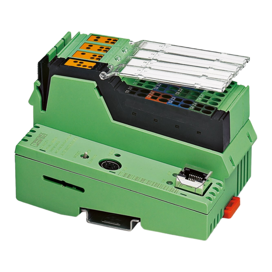
Summarization of Contents
Foreword
Purpose of this user manual
Explains how to start up and operate the Inline controllers, covering essential functions and setup procedures.
Hardware and software requirements
Details the necessary hardware components and software versions for using the Inline controller effectively.
General safety notes
Provides crucial safety instructions and regulations to follow during installation and operation of the Inline controller.
Intended use
Describes the intended applications and operational environment for the modular Inline controller.
Disposal
Provides guidelines for the proper and environmentally compliant disposal of the Inline controller unit.
Description of the Inline controller
General description of the Inline controller
Offers an overview of the Inline controller's features, including its modular design, integrated interfaces, and core functionalities.
Possible fields of application
Outlines the various industrial scenarios and system configurations where the Inline controller can be utilized.
Notes on using the Inline controller in potentially explosive areas
Details specific precautions and installation requirements for operating the Inline controller in hazardous environments.
Connection and operating elements
Identifies and explains the function of each physical component and connector on the Inline controller.
Diagnostics and status indicators
Explains the meaning of various LEDs and diagnostic indicators for monitoring the controller's operational status.
Mounting and removing the Inline controller
Provides step-by-step instructions and considerations for safely installing and uninstalling the Inline controller.
Communication paths
Describes the available methods for establishing communication with the Inline controller via Ethernet and serial interfaces.
Power supply
Details the requirements and procedures for connecting external power supplies to the Inline controller.
Digital inputs and outputs
Explains the configuration and assignment of the controller's digital input and output terminals.
The Inline controller under PC Worx/PC Worx Express
Software version
Specifies the required versions of PC Worx and PC Worx Express software for controller operation.
Creating a new project
Guides users through the process of setting up a new project in PC Worx/PC Worx Express for the Inline controller.
Assigning the IP address for the controller
Explains methods like DCP and BootP for configuring the network settings and IP address of the controller.
The Inline controller as a PROFINET device
Details how to integrate and configure the Inline controller as a PROFINET device within a network.
Functions of the plug-in parameterization memory (SD card)
Describes how to use the SD card for storing programs, configurations, and application data.
Parameterization memory and Internet Explorer
Covers managing parameterization memory files and accessing them via FTP using Internet Explorer.
Activating/deactivating the FTP server
Explains how to secure the controller by enabling or disabling the FTP server functionality.
Function blocks for Ethernet communication
Lists and describes function blocks used for establishing TCP/IP and UDP/IP communication over Ethernet.
Alignment
Explains how data alignment in memory can affect processing and how to manage 'data gaps'.
System variables and status information
Status register for local digital inputs and outputs
Details system variables used to read the state of local digital inputs and control digital outputs.
Diagnostic status register
Explains system variables that provide information on the controller's operating state and diagnostic status.
Diagnostic parameter register
Describes system variables that provide detailed information on errors indicated in the diagnostic status register.
PROFINET register
Lists PROFINET-specific system variables for monitoring the controller's status in a PROFINET network.
IEC 61131 runtime system
Details system variables related to the controller's IEC 61131 programming environment and runtime status.
Control processor
Shows system variables that reflect the status of the controller's internal control processor.
Power supplies
Lists system variables used to monitor the status of the main, input, and output power supplies.
Technical data and ordering data
Technical data
Provides detailed specifications for the controller's hardware, electrical characteristics, and environmental ratings.
Ordering data
Lists part numbers, order codes, and package quantities for controller modules, accessories, software, and documentation.
Appendix: service, maintenance, derating, and ambient conditions
Error causes and remedies
Lists common installation errors, their causes, and recommended solutions for troubleshooting.
Updating the Inline controller firmware
Explains the process for updating the controller's firmware to add new functions or improve performance.
Connecting unshielded cables
Provides instructions and best practices for wiring I/O devices and power using unshielded cables.
Derating
Details how ambient temperature affects the controller's current output and power dissipation.
Tested successfully under extreme ambient conditions
Describes test results and conditions for controller operation in extreme temperature and humidity environments.
Appendix for document lists
List of figures
Provides a comprehensive list of all figures and their corresponding page numbers for easy reference.
List of tables
Provides a comprehensive list of all tables and their corresponding page numbers for easy reference.


Need help?
Do you have a question about the ILC 151 ETH and is the answer not in the manual?
Questions and answers