Table of Contents
Advertisement
Quick Links
See also:
User Manual
Advertisement
Table of Contents

Related Manuals for Phoenix Contact FL SWITCH GHS 12G/8


Summary of Contents for Phoenix Contact FL SWITCH GHS 12G/8
- Page 1 User manual for FL SWITCH GHS 12G/8(-L3) FL SWITCH GHS 4G/12(-L3) User manual UM EN FL SWITCH GHS Order No. —...
- Page 2 UM EN FL SWITCH GHS Revision: Order No.: — This user manual is valid for: Designation Version Order No. FL SWITCH GHS 12G/8 2989200 FL SWITCH GHS 4G/12 2700271 FL FXT 2989307 FL SWITCH GHS 12G/8-L3 2700787 FL SWITCH GHS 4G/12-L3...
- Page 3 How to contact us Internet Up-to-date information on Phoenix Contact products and our Terms and Conditions can be found on the Internet at: phoenixcontact.com Make sure you always use the latest documentation.
- Page 4 The receipt of technical documentation (in particular user documentation) does not constitute any further duty on the part of Phoenix Contact to furnish information on modifications to products and/or technical documentation. You are responsible to verify the suitability and intended use of the products in your specific application, in particular with regard to observing the applicable standards and regulations.
-
Page 5: Table Of Contents
CLI via V.24 (RS-232) - General function ..........42 3.3.3 CLI via SSH - General function ............46 Web-based management ..................47 SNMP management .................... 48 3.5.1 SNMP interface ..................48 Configuring the Telnet terminal................50 Startup .............................53 Basic settings ...................... 53 8016_en_02 PHOENIX CONTACT... - Page 6 6.1.2 Firmware backup ................. 81 6.1.3 SNMP ....................81 6.1.4 CLI ....................... 81 Configuration file transfer ......................83 Configuration file transfer via TFTP ..............83 Configuration file transfer via HTTP ..............83 PROFINET ..........................85 Selecting PROFINET mode................. 85 PHOENIX CONTACT 8016_en_02...
- Page 7 SNMP ....................99 10.5.3 CLI ..................... 100 10.6 Managing user accounts ................... 100 10.6.1 WBM ....................100 10.6.2 SNMP ....................101 10.6.3 CLI ..................... 101 10.7 Activating/deactivating port security or IEEE 802.1x.......... 101 10.7.1 WBM ....................101 8016_en_02 PHOENIX CONTACT...
- Page 8 CLI ..................... 113 11.4 VLAN Advanced Config..................114 11.4.1 WBM ....................114 11.4.2 SNMP ....................114 11.4.3 CLI ..................... 115 11.5 VLAN port configuration ..................115 11.5.1 WBM ....................115 11.5.2 SNMP ....................115 11.5.3 CLI ..................... 116 PHOENIX CONTACT 8016_en_02...
- Page 9 Diffserv rules table ................128 14.5 POF-SCRJ diagnostics ..................128 14.5.1 WBM ....................129 14.5.2 SNMP ....................130 14.5.3 CLI ..................... 130 14.6 Configuring port mirroring .................. 130 14.6.1 WBM ....................130 14.6.2 SNMP ....................131 14.6.3 CLI ..................... 131 8016_en_02 PHOENIX CONTACT...
- Page 10 Configuring storm control .................. 141 15.3.1 WBM ....................141 15.3.2 SNMP ....................141 15.3.3 CLI ..................... 141 15.4 Configuring traffic shaping................. 142 15.4.1 WBM ....................142 15.4.2 SNMP ....................142 15.4.3 CLI ..................... 142 15.5 Differentiated services ..................143 PHOENIX CONTACT 8016_en_02...
- Page 11 Creating an ARP entry ............... 165 18.4.2 SNMP ....................166 18.4.3 CLI ..................... 166 18.4.4 ARP configuration (global) ..............166 18.4.5 SNMP ....................167 18.4.6 CLI ..................... 167 18.4.7 The ARP table ..................167 18.4.8 SNMP ....................168 18.4.9 CLI ..................... 168 8016_en_02 PHOENIX CONTACT...
- Page 12 Enabling the web pages for multicast filtering in WBM ........197 19.3 Static multicast groups ..................197 19.3.1 “Current Multicast Groups” web page ..........198 19.3.2 Creating static multicast groups ............198 19.3.3 Procedure for creating a multicast group ........... 200 PHOENIX CONTACT 8016_en_02...
- Page 13 Technical data ....................205 20.1.1 Revision history of this manual ............208 20.2 Typical current consumption - GHS (example) ..........209 20.3 Ordering data ....................210 20.3.1 Ordering data - GHS ................210 20.3.2 Accessories ..................210 8016_en_02 PHOENIX CONTACT...
- Page 14 FL SWITCH GHS PHOENIX CONTACT 8016_en_02...
-
Page 15: Gigabit Modular Switches
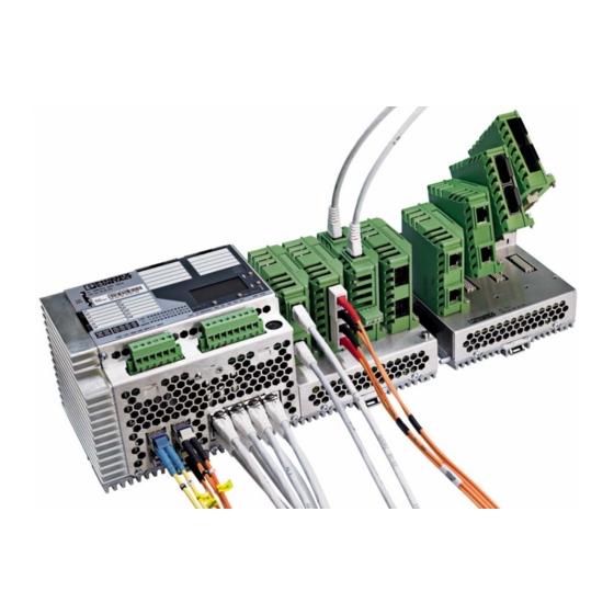
Gigabit ports and support modular extension up to 28 or 24 ports. FL SWITCH GHS 12G/8 On the FL SWITCH GHS 12G/8, the twelve Gigabit ports are divided into four Gigabit fiber optic interfaces with SFP modules and eight twisted pair Gigabit ports. In addition, a further eight 100 Mbps ports can be connected using FL IF... -
Page 16: New Performance Class For Future-Proof Networks
Support of redundant Gigabit backbones – Link aggregation according to IEEE 802.3ad/port trunking can be used as an option to further increase the available bandwidth by bundling two to eight cables to create a single logical connection. PHOENIX CONTACT 8016_en_02... -
Page 17: Order No
CLI, web- based management or SNMP. Routing Support of numerous routing methods; the additional FL SD Flash/L3/MRM license (Order No. 2700607) is required to activate them. PROFIenergy Support of the PROFIenergy function. 8016_en_02 PHOENIX CONTACT... -
Page 18: Ghs Device View
Backwards compatibility with existing IF modules – Configuration can be saved on SD Flash cards – SNMP v1, v2, v3 – User and access management 1.2.1 GHS device view 1.2.1.1 Elements of the head station Figure 1-3 Elements of the head station PHOENIX CONTACT 8016_en_02... -
Page 19: Dimensions Of The Gigabit Modular Switch
Status indicators for the sensors and sensor supply Diagram of port numbering Status indicators for the ports of the Ethernet ports 1.2.2 Dimensions of the Gigabit Modular Switch 413,5 286,5 FL SWITCH GHS 12G/8 Ord.No. 29 89 200 Address FAIL DI2 UI MODE RESET... -
Page 20: View Of The Interface Modules (Example)
These latches must be pressed in order to remove the interface module (loosen the mounting screw first). – Ethernet ports These are the ports for the various interfaces and connection directions. – Marking groove for ZBF ... zack marker strip – Mounting screws to lock the interface modules in place PHOENIX CONTACT 8016_en_02... -
Page 21: Mounting And Installation
Mount the head station on a clean DIN rail according to DIN EN 50022 (e.g., NS 35 ... from Phoenix Contact). To avoid contact resistance, only use clean, corrosion-free DIN rails. To avoid impermissible loads on the switch in the event of high mechanical strain (strong vibrations or shocks), the DIN rail used should be secured tightly to prevent it from twisting. - Page 22 Pull down the positive latches using a suitable tool (e.g., screwdriver). Both positive latches remain snapped out. Then swivel the bottom of the module away from the DIN rail slightly (A). Next, lift the module upwards away from the DIN rail (B). Figure 2-2 Removing the head station PHOENIX CONTACT 8016_en_02...
-
Page 23: Mounting And Removing The Extension Module
(A) until the connector/socket strip of both modules snap into each other with no gap between the sides of both modules. Secure the connection using the two screws (C). FL SWITCH GHS 12G/8 Ord.No. 29 89 200 Address... - Page 24 Pull down the holding latches using a suitable tool (e.g., screwdriver). Then swivel the bottom of the module away from the DIN rail slightly (A). Next, lift the module upwards away from the DIN rail. Figure 2-5 Removing extension modules PHOENIX CONTACT 8016_en_02...
-
Page 25: Installing The Ghs
A bridge between US1 and US2 prevents this error message. It is also possible to deactivate monitoring via the management interfaces. 2.3.1.1 Example: Supplying the device from one voltage source FL SWITCH GHS 12G/8 Ord.No. 29 89 200 Address FAIL... - Page 26 FL SWITCH GHS 2.3.1.2 Example: Supplying the device from multiple voltage sources FL SWITCH GHS 12G/8 Ord.No. 29 89 200 Address FAIL DI2 UI MODE RESET GNDI GNDI V.24 Alarm 2 Alarm 1 GNDI +24V Figure 2-7 Supplying the system using multiple voltage sources...
-
Page 27: Mounting And Removing The Interface Modules
Now push the interface modules towards the basic module until the connector and the holding clamp are snapped into place. Secure the interface module using the screw on the bottom right-hand side of the interface module. Figure 2-9 Securing the interface module 8016_en_02 PHOENIX CONTACT... -
Page 28: Use Of Sfp Slots
The SFP modules are available separately as accessories, see Unknown source of cross- reference. Phoenix Contact only recommends using SFP modules listed in the ordering data on Unknown source of cross-reference. PHOENIX CONTACT 8016_en_02... -
Page 29: Elements Of The Sfp Modules
Inserting the SFP modules FL SWITCH GHS 4G12: Inserting an SFP module disables the corresponding RJ45 port. When an RJ45 port is automatically disabled by an SFP module, the Link LED on the RJ45 port lights up orange. 8016_en_02 PHOENIX CONTACT... - Page 30 Removing the fiber optic connectors Removing the SFP modules • Remove the fiber optic connector before removing the SFP module. • Turn the release latch (A) down and pull out the SFP module (B). Figure 2-15 Removing the SFP modules PHOENIX CONTACT 8016_en_02...
-
Page 31: Starting Up The Interface Modules
Ports that are not being used are considered as cable interrupts. In addition, a TP/TX path to a deactivated terminal device is also considered a cable interrupt, as the connected device cannot send a link test pulse because it is switched off. 8016_en_02 PHOENIX CONTACT... -
Page 32: Fl If 2Fx Sc
To prevent dirt from entering the connectors, do not remove the dust protection caps until just before the connectors are connected. The same applies for the protective caps on the connectors. 68740020 Figure 2-16 Connecting the SC-D connectors PHOENIX CONTACT 8016_en_02... - Page 33 36,000 m, maximum Single mode fiberglass 10,000 m, maximum Multi-mode fiberglass 68741021 FL IF 2FX SC-F FL IF 2FX SC-F FL IF 2FX SM SC-F FL IF 2FX SM SC-F Figure 2-18 Fiber optic connection between devices 8016_en_02 PHOENIX CONTACT...
-
Page 34: Fl If 2Fx St-D / Fl If 2Pof Scrj-D
FL IF MEM 2TX-D/MRM is not available when using the GHS and is implemented instead by means of the SD Flash card. The RJ45 ports of the modules can still be used. 2.6.3.1 Network connection See “FL IF 2TX VS-RJ ...” on page 29 onwards. PHOENIX CONTACT 8016_en_02... -
Page 35: Fl If 2Pse-F
The module has a green LED for each port, which indicates the PoE mode. The LED is active if the PoE supply and a PD (powered device) are connected. The LED flashes if the module is supplied with less than 48 V. 8016_en_02 PHOENIX CONTACT... -
Page 36: Table 2-1 Pin Assignment Of Poe Ports
Table 2-1 Pin assignment of PoE ports Assignment Description Assignment Description RX+/48 V DC Data/PoE + n. c. RX-/48 V DC Data/PoE + TX-/0 V Data/PoE - TX+/0 V Data/PoE - n. c. n. c. n. c. PHOENIX CONTACT 8016_en_02... -
Page 37: User Interfaces
For extended configuration of the device to be supported, this function must be enabled on the “General Configuration, Management Interfaces, Display Rights” web page (default: “Enable”). Figure 3-1 “Display Rights” web page The structure of the configuration using the display is shown in Figure 3-4 on page 40. 8016_en_02 PHOENIX CONTACT... -
Page 38: Handling The Display
There are four buttons for controlling the contents of the display. The selected information is displayed in white text on a gray background. “ACT” is activated in the figure below. System operational FL SWITCH GHS 12G/8 Ord.No. 29 89 200 Address... -
Page 39: Meaning Of The Display Contents
Each event is indicated by a combination of three letters. When the cursor is positioned over the event using the selection buttons, explanatory text is displayed above the bottom line in the display. Display Meaning MRP ring failure Link monitor alarm PROFINET connection 8016_en_02 PHOENIX CONTACT... -
Page 40: Leds On The Switch And The Extension Module
In conjunction with the LEDs for port 1 (X1) to port 12 (X12), the device now indicates the following information: – Only port 1, port 3, and port 4 are connected and have a link. – Data is currently only being transmitted via port 1. PHOENIX CONTACT 8016_en_02... - Page 41 User interfaces System operational FL SWITCH GHS 12G/8 Ord.No. 29 89 200 Address FAIL MENU MODE DI2 UI MODE RESET GNDI GNDI V.24 80160005 Figure 3-3 Example of status indicators 8016_en_02 PHOENIX CONTACT...
- Page 42 RSTP RSTP Info RSTP Setting MRP Status MRM Function LLDP LLDP Info LLDP Settings Link Aggregation Test Member Ports Link Monitoring Storm Control 802.1X Security MAC based Security Routing Save Figure 3-4 Structure of the display configuration PHOENIX CONTACT 8016_en_02...
-
Page 43: Rs-232) Interface For External Management
If the command is not found, the message that is output indicates the error. Example: The user wants to execute the “logout” command, but enters the command incorrectly and presses <Enter>. The CLI then outputs an error message: (FL SWITCH GHS) >logout Error[1]: Invalid command 'logout' 8016_en_02 PHOENIX CONTACT... -
Page 44: Cli Via V.24 (Rs-232) - General Function
PC (e.g., HyperTerminal under Windows) and enables access to the serial interface. The reference potentials of the V.24 (RS-232) interface and the supply voltage are not electrically isolated. PHOENIX CONTACT 8016_en_02... -
Page 45: Order No
PC (e.g., HyperTerminal under Windows or PuTTY) and enables access to the CLI user interface. The reference potentials of the V.24 (RS-232) interface and the supply voltage are not electrically isolated. 8016_en_02 PHOENIX CONTACT... -
Page 46: Order No
After establishing the connection, press the <Enter> key on the PC. The screen contents are then requested by the switch and you have the option of choosing between the CLI and the serial configuration menu. Select “1” for the CLI. Figure 3-8 CLI screen PHOENIX CONTACT 8016_en_02... - Page 47 CLI changes from “>” to “#”. Procedure: • Call the CLI as described above. • Log in. • Enter “enable”. Confirm the password prompt that then appears by pressing <Enter>. 80160007 Figure 3-9 Calling the list of arguments and privilege mode 8016_en_02 PHOENIX CONTACT...
-
Page 48: Cli Via Ssh - General Function
The IP address consists of four decimal numbers ranging from 0 to 255. These four decimal numbers are separated by dots. Example: 172.16.116.200 Figure 3-10 SSH client screen When the CLI is called, you must log in. The default settings are: User: admin Password: private PHOENIX CONTACT 8016_en_02... -
Page 49: Web-Based Management
To do this, http or https can be used, this selection is made in the management interface. Comprehensive configuration and diagnostic functions are clearly displayed on a graphical user interface. Every user with a 8016_en_02 PHOENIX CONTACT... -
Page 50: Snmp Management
RFC1213, RMON MIB, Bridge MIB, If MIB, Etherlike MIB, Iana-address-family MIB, IANAifType MIB, SNMPv2 MIB, SNMP-FRAMEWORK MIB, P Bridge MIB, Q Bridge MIB, RSTP MIB, LLDP MIB, pnoRedundancy MIB, inetaddress, and private SNMP objects from Phoenix Contact (FL-SWITCH-M MIB). PHOENIX CONTACT 8016_en_02... -
Page 51: Table 3-2 Traps For The Ghs
User interfaces Phoenix Contact provides notification of ASN1 SNMP objects by publishing their descriptions on the Internet. Reading SNMP objects is not password-protected. However, a password is required for read access in SNMP, but this is set to “public”, which is usual for network devices, and cannot be modified. -
Page 52: Configuring The Telnet Terminal
Trap to test the connection between the SNMP agent and the network management station. Private MIBs The private MIBs for the GHS from Phoenix Contact can be found under object ID 1.3.6.1.4.1.4346. The GHS MIB contains the following groups: –... - Page 53 In privilege mode, you have access to all the Telnet options. You can tell that you are in privilege mode, as the cursor in Telnet changes from “>” to “#”. Procedure: • Call Telnet as described above. • Log in. 8016_en_02 PHOENIX CONTACT...
- Page 54 FL SWITCH GHS • Enter “enable”. Confirm the password prompt that then appears by pressing <Enter>. Figure 3-14 Switching to privilege mode and calling the list of arguments PHOENIX CONTACT 8016_en_02...
-
Page 55: Startup
– The switch is in “Ethernet” mode (default setting). – The WBM refresh interval is set to 30 seconds. – Management is in VLAN 1. – The SNTP function (automatic setting of the system time) is deactivated. 8016_en_02 PHOENIX CONTACT... -
Page 56: Activating The Default Ip Address
“BootP” function can be deactivated via the management. The assignment of valid IP parameters is vital to the management function of the switch. If the switch has not been assigned valid IP parameters, “No IP assigned 01” will appear in the display. PHOENIX CONTACT 8016_en_02... -
Page 57: Assigning Ip Parameters Via Ipassign
IP parameters very easily using BootP. IPAssign can be found at phoenixcontact.com. Procedure • Connect the switch to the PC and start IPAssign. The tool then displays the devices that are sending BootP requests to assign an IP. Figure 4-1 Devices sending BootP requests in IPAssign 8016_en_02 PHOENIX CONTACT... -
Page 58: Example For V.24 (Rs-232) As A Serial Connection
Example for V.24 (RS-232) as a serial connection Establish a communication connection as described in Section 3.2 “V.24 (RS-232) interface for external management”. Changing the IP address • Open the serial interface and log in. • The default settings are: User: admin Password: private PHOENIX CONTACT 8016_en_02... -
Page 59: Assigning Ip Parameters Via The Cli And Ssh
(see Section “Calling privilege mode” on page 45). • Enter the following: “network parms <IP address> <Subnet mask> <Default gateway>”. Example: The new IP is: 172.16.116.100, the subnetwork is 255.255.255.0, there is no default gateway. SSH entry in privilege mode: network parms 172.16.116.100 255.255.255.0 8016_en_02 PHOENIX CONTACT... - Page 60 If your entry has been rejected with the message “Network protocol must be none to set IP address”, you must first disable the active IP address assignment mechanism and then assign the IP statically to the device. To disable IP assignment mechanisms, please enter the following (in privilege mode): network protocol none PHOENIX CONTACT 8016_en_02...
-
Page 61: Assigning Ip Parameters Via Dhcp/Dcp
Assigning IP parameters via DHCP/DCP By default upon delivery, it is not possible to assign IP parameters via DHCP or DCP. To activate these mechanisms, set the device to the desired operating mode via V.24 (RS- 232), CLI or WBM. 8016_en_02 PHOENIX CONTACT... -
Page 62: Modifying Ip Parameters
BootP server and displayed in the message window. If you are operating other devices in the same network, messages from these devices may also be displayed. Messages from Phoenix Contact Factoryline components can be easily identified by their MAC address, which starts with 00.A0.45... and is provided on the devices. - Page 63 In order to make changes, you must log into the device. Click on “Login” at the top of the web page. Figure 4-7 “IP Configuration” web page • The default settings are: User: admin Password: private • Return to the “General Configuration, IP Configuration” page. 8016_en_02 PHOENIX CONTACT...
-
Page 64: Changing Ip Parameters Via The Cli
In order to use SNMP management, the switch must already have an IP address. This IP address may, for example, have been set via the CLI or the serial connection or may have been assigned via the automatic BootP or DHCP mechanisms (see also 4.3.1 “Assigning IP parameters via IPAssign”). PHOENIX CONTACT 8016_en_02... -
Page 65: Password Concept
The concept is valid for the first ten users logged in simultaneously. All other users must confirm each configuration modification by entering the password, until less than ten users are logged in. A user can assign various rights to other users. 8016_en_02 PHOENIX CONTACT... -
Page 66: Using Smart Mode
After restarting the device, press and hold down “Activate” for around five seconds until the display shows “Smart Mode/Easy Setup”. If Smart mode is active, “Smart Mode” will appear in the display. SMART MODE FL SWITCH GHS 12G/8 Ord.No. 29 89 200 EASY Address... -
Page 67: Startup Using The Mdc Wizard
Spanning Tree Protocol (RSTP), Media Redundancy Protocol (MRP), trap receiver, Link Layer Discovery Protocol (LLDP) or Virtual Local Area Networks (VLANs) can be parameterized simultaneously for various selected devices. Time-consuming individual adjustment and modification of device functions via web-based management is thus eliminated. 8016_en_02 PHOENIX CONTACT... -
Page 68: Calling A New Project Under Config
Figure 4-12 New project under Config+ The arrangement of the windows can be changed. Here the “Bus Structure”, “Device Catalog”, “DTM View”, “Device Details”, and “Output Details” windows are open and recommended for use (see Figure 4-12). PHOENIX CONTACT 8016_en_02... - Page 69 Startup A virtual PC must be integrated into the project. => Locate AXSNMP 1.0 in the device catalog under “Phoenix Contact, FDT, PC” and integrate it in the bus configuration under the project (see Figure 4-13). Figure 4-13 Selecting the desired components Select the desired Ethernet components from the device catalog and append under the AXSNMP virtual PC;...
- Page 70 Following correct entry, this data will appear as circled in Figure 4-15. All accessible and THEREFORE configurable devices can be displayed via the context menu by right-clicking on “AXSNMP, DTM Functions, Device List” in “DTM View” (see Figure 4-16). Figure 4-16 Context menu - “DTM View” PHOENIX CONTACT 8016_en_02...
-
Page 71: Configuration Using The Mdc Wizard
In the table, devices can be enabled or disabled simultaneously (see Figure 4-18/item 2). • Trap targets are specified for the first and/or second address (see Figure 4-18/item 3). • Step 4: Start downloading the settings. • Step 5: Close MDC. 8016_en_02 PHOENIX CONTACT... - Page 72 In the table, devices that are not to be modified can be deactivated (uncheck device). • In the table, devices can be simultaneously selected as “Transparent” or “Tagging” (see Figure 4-19). • Step 4: Start downloading the settings. • Step 5: Close MDC. Figure 4-19 Selecting the tagging mode PHOENIX CONTACT 8016_en_02...
- Page 73 Step 4: Start downloading the settings. • Step 5: Close MDC. The MDC automatically activates the web pages in the devices and RSTP. When disabled, only the function is deactivated, not the web page display. 4.7.2.5 MRP activation/deactivation • Call MDC. 8016_en_02 PHOENIX CONTACT...
- Page 74 Step 4: Start downloading the settings. • Step 5: Close MDC. This procedure must then be repeated: • Call MDC. • Step 1: Select the MRP function. • Step 2: Select the “Activate MRP Configuration” option (see Figure 4-22/item 2). PHOENIX CONTACT 8016_en_02...
- Page 75 In the last column of the table, the time within which the switch sends the LLDP information to the network via BPDU is set for each device. • Step 4: Start downloading the settings. • Step 5: Close MDC. 8016_en_02 PHOENIX CONTACT...
- Page 76 FL SWITCH GHS PHOENIX CONTACT 8016_en_02...
-
Page 77: Administrative Settings
“System Identification” menu 5.1.2 SNMP The settings can be found under OID 1.3.6.1.2.1.1 under the following path: Full path: iso(1).org(3).dod(6).internet(1).mgmt(2).mib-2(1).system(1) 5.1.3 The settings can be found in the CLI under “show sysinfo”. CLI user manual: Unknown source of cross-reference 8016_en_02 PHOENIX CONTACT... -
Page 78: Saving The Configuration
WBM can only be called using a valid IP address. Once the switch has been reset to its default settings, it has no valid IP address and the addressing mechanism is set to BootP. 5.2.2 SNMP The settings can be found under OID 1.3.6.1.4.1.4346.11.11.11.2.5 under the following path: Full path: iso(1).org(3).dod(6).internet(1).private(4).enterprises(1).phoenixContact(4346).pxcFactor yLine(11).flWorkDevice(11).flWorkFirmware(11).flWorkFWCtrl(2).flWorkFWCtrlConf(5) PHOENIX CONTACT 8016_en_02... -
Page 79: Cli
Please note that the recovery procedure requires a folder with the name “FLRecovery”. Insert the SD card into the GHS switch. Start the switch. Once started, the device deletes the Recovery file and saves the configuration on the device. 8016_en_02 PHOENIX CONTACT... - Page 80 FL SWITCH GHS Sequence: Figure 5-3 Device start with SD card PHOENIX CONTACT 8016_en_02...
-
Page 81: Software Update
To select the old firmware, refer to Section 6.2 “Dual Image”. 6.1.1 In the “Software Update” menu, you can view or modify the parameters for a software update and trigger the update. There are two options available for updating the software: Update via “TFTP”: 8016_en_02 PHOENIX CONTACT... - Page 82 A reset is not carried out automatically following a firmware update. The desired option can be selected in WBM. There are no assurances that all existing configuration data will be retained after a firmware update/downgrade. Please therefore check the configuration settings or reset the device to the default delivery settings. PHOENIX CONTACT 8016_en_02...
-
Page 83: Firmware Backup
6.1.4 If you use a serial connection for software update, please note that transfer can take over 30 minutes. The settings can be found in the CLI under “copy”. CLI user manual: Unknown source of cross-reference 8016_en_02 PHOENIX CONTACT... - Page 84 FL SWITCH GHS PHOENIX CONTACT 8016_en_02...
-
Page 85: Configuration File Transfer
PC to the switch, the switch must be restarted to activate the new configuration. Two options are available for the file transfer: Configuration file transfer via TFTP Figure 7-1 “Configuration File Transfer” web page - TFTP enabled Configuration file transfer via HTTP 8016_en_02 PHOENIX CONTACT... -
Page 86: Figure 7-2 "Configuration File Transfer" Web Page - Http Enabled
FL SWITCH GHS Figure 7-2 “Configuration File Transfer” web page - HTTP enabled PHOENIX CONTACT 8016_en_02... -
Page 87: Profinet
LLDP with the default name “FL SWITCH ...” and the IP address “0.0.0.0”. The switch indicates in the display that it is waiting for a valid IP configuration via DCP. The switch cannot be accessed via other network services such as ping at this time. 8016_en_02 PHOENIX CONTACT... -
Page 88: Wbm
The settings can be found under OID 1.3.6.1.4.1.4346.11.11.11.2.1.10 under the following path: Full path: iso(1).org(3).dod(6).internet(1).private(4).enterprises(1).phoenixContact(4346).pxcFactor yLine(11).flWorkDevice(11).flWorkFirmware(11).flWorkFWCtrl(2).flWorkFWCtrlBasic(1).fl WorkFWCtrlOperatingMode(10) 8.1.3 The settings for activation can be found in the CLI under “OperatingMode_Profinet”. The other settings can be found under “configure/Profinet”. CLI user manual: Unknown source of cross-reference PHOENIX CONTACT 8016_en_02... -
Page 89: Process Data Communication
POF SCRJ diagnostics 0x03 Port or 0xFF 0x04 Port or 0xFF Power supply 0x05 0x00 0x06 0x00 Interface removed 0x07 0x00 0x08 0x00 MRP ring failure 0x09 0x00 0x0a 0x00 Link enable status 0x20 Port 0x21 Port 8016_en_02 PHOENIX CONTACT... -
Page 90: Additional Process Data
Far End Fault status: 0 - No fault; 1 - Fault – Port enable status: 0 - Enabled; 1 - Disabled – Link mode: 0 - Forwarding; 1 - Blocking 6 5 4 3 2 Meaning Link Port enable Far End Fault Link status mode PHOENIX CONTACT 8016_en_02... -
Page 91: Activating And Configuring Redundancy Mechanisms
Spanning Tree variant. When using more than one virtual LAN (VLAN) in a network, the Multiple Spanning Tree Protocol (MSTP) redundancy mechanism defined in IEEE 802.1q is also supported. Figure 9-1 “Spanning Tree Config” web page 8016_en_02 PHOENIX CONTACT... -
Page 92: Snmp
The “Maximum Age of STP”, “Hello Time”, and “Forward Delay” parameters are optimized by default upon delivery. They should not be modified. 9.1.2 SNMP The settings can be found under OID 1.3.6.1.4.1.4346.11.11.15.4 under the following path: Full path: iso(1).org(3).dod(6).internet(1).private(4).enterprises(1).phoenixContact(4346).pxcFactor yLine(11).flWorkDevice(11).flSwitch(15).flSwitchRedundancy(4) PHOENIX CONTACT 8016_en_02... -
Page 93: Cli
The license can be inserted and activated later during runtime. Removal of the license during runtime is not recommended. Only FL SD Flash/MRM cards (Order No. 2700270) from Phoenix Contact can be used for licensing. Formatting the card will result in irrevocable loss of the MRP license. -
Page 94: Wbm
SNMP The settings can be found under OID 1.3.6.1.4.1.4346.11.11.11.2.10.1 under the following path: Full path: iso(1).org(3).dod(6).internet(1).private(4).enterprises(1).phoenixContact(4346).pxcFactor yLine(11).flWorkDevice(11).flWorkFirmware(11).flWorkFWCtrl(2).flWorkFWCtrlMRP(10).f lWorkFWCtrlMRPConfig(1) 9.2.3 The settings can be found in the CLI under “show mrp”. CLI user manual: Unknown source of cross-reference PHOENIX CONTACT 8016_en_02... -
Page 95: Activating Security Mechanisms
In the “General Configuration, Change Password” menu, you can change and activate the current passwords. Figure 10-1 “Change Password” web page 10.1.2 SNMP The settings can be found under OID 1.3.6.1.4.1.4346.11.11.11.2.3 under the following path: Full path: iso(1).org(3).dod(6).internet(1).private(4).enterprises(1).phoenixContact(4346).pxcFactor yLine(11).flWorkDevice(11).flWorkFirmware(11).flWorkFWCtrl(2).flWorkFWCtrlPasswd(3 8016_en_02 PHOENIX CONTACT... -
Page 96: Cli
Forgotten your password? Call the Phoenix Contact phone number listed in the Appendix, making sure you have the device serial number and MAC address to hand. -
Page 97: Wbm
In the “General Configuration, Management Interfaces, Security Configuration” menu, you can generate and upload/download the security context. Figure 10-2 “General Security Configuration” web page 10.2.2 SNMP The settings can be found under OID 1.3.6.1.4.1.4346.11.11.20.1.5.3 under the following path: Full path: iso(1).org(3).dod(6).internet(1).private(4).enterprises(1).phoenixContact(4346).pxcFactor yLine(11).flWorkDevice(11).flWorkSecurity(20).flWorkSecurityCtrl(1).flWorkSecurityCtrlCl ientAuth(5).flWorkSecurityCtrlGenSecurityContext(3) 8016_en_02 PHOENIX CONTACT... -
Page 98: Web Server Protocol
“HTTPS” web page 10.3.2 SNMP For HTTP: The settings can be found under OID 1.3.6.1.4.1.4346.11.11.11.2.1.6 under the following path: Full path: iso(1).org(3).dod(6).internet(1).private(4).enterprises(1).phoenixContact(4346).pxcFactor yLine(11).flWorkDevice(11).flWorkFirmware(11).flWorkFWCtrl(2).flWorkFWCtrlBasic(1).fl WorkFWCtrlHTTP(6) For HTTPS: The settings can be found under OID 1.3.6.1.4.1.4346.11.11.11.2.1.12 under the following path: PHOENIX CONTACT 8016_en_02... -
Page 99: Cli
The end result is the same as if sitting at the remote console. 8016_en_02 PHOENIX CONTACT... -
Page 100: Snmp
Full Path: iso(1).org(3).dod(6).internet(1).private(4).enterprises(1).phoenixContact(4346).pxcFactor yLine(11).flWorkDevice(11).flWorkFirmware(11).flWorkFWCtrl(2).flWorkFWCtrlBasic(1).fl WorkFWCtrlSSH(13) For Telnet: The settings can be found under OID 1.3.6.1.4.1.4346.11.11.11.2.12.3 under the following path: Full path: iso(1).org(3).dod(6).internet(1).private(4).enterprises(1).phoenixContact(4346).pxcFactor yLine(11).flWorkDevice(11).flWorkFirmware(11).flWorkFWCtrl(2).flWorkFWCtrlTelnetGro up(12).flWorkFWCtrlTelnetAllowNewMode(3) 10.4.3 For SSH: The settings can be found in the CLI under “ip ssh”. PHOENIX CONTACT 8016_en_02... -
Page 101: Activating Snmp
“SNMP” web page 10.5.2 SNMP For SNMP on/off: The settings can be found under OID 1.3.6.1.4.1.4346.11.11.11.2.1.9 under the following path: Full path: iso(1).org(3).dod(6).internet(1).private(4).enterprises(1).phoenixContact(4346).pxcFactor yLine(11).flWorkDevice(11).flWorkFirmware(11).flWorkFWCtrl(2).flWorkFWCtrlBasic(1).fl WorkFWCtrlSNMP(9) For SNMPv3: The settings can be found under OID 1.3.6.1.4.1.4346.11.11.11.2.1.14 under the following path: 8016_en_02 PHOENIX CONTACT... -
Page 102: Cli
10.6.1 In the “General Configuration, User Account Management, User Account” menu, you can manage the user accounts. Figure 10-6 “User Accounts” web page PHOENIX CONTACT 8016_en_02... -
Page 103: Snmp
IEEE 802.1x 10.7.1 In the “Switch Station, Ports, Ext. Port Configuration, General Security Configuration” menu, you can enable or disable the use of port security or the IEEE 802.1x function. Figure 10-7 “General Security Configuration” web page 8016_en_02 PHOENIX CONTACT... -
Page 104: Snmp
The settings for Port Security can be found in the CLI under “configure/port-security”. CLI user manual: Unknown source of cross-reference The settings for IEEE 802.1x can be found in the CLI under “configure/dot1x”. CLI user manual: Unknown source of cross-reference PHOENIX CONTACT 8016_en_02... -
Page 105: Configuring 802.1X
Figure 10-8 “802.1x Configuration” web page 10.8.2 SNMP The settings can be found under OID 1.3.6.1.4.1.4346.11.11.11.2.8.3.1.1 under the following path: Full path: iso(1).org(3).dod(6).internet(1).private(4).enterprises(1).phoenixContact(4346).pxcFactor yLine(11).flWorkDevice(11).flWorkFirmware(11).flWorkFWCtrl(2).flWorkFWCtrlSecurity(8 ).flWorkFWCtrlSecurityDot1x(3).flWorkFWCtrlSecurityDot1xPortTable(1).flWorkFWCtrlSe curityDot1xPortEntry(1) 10.8.3 The settings can be found in the CLI under “configure/ot1x port-control”. 8016_en_02 PHOENIX CONTACT... -
Page 106: Configuring The Radius Server
For example, members of an external service team can log into a network without the definition of open guest access or similar. 10.9.1 In the “General Configuration, User Account Management, RADIUS Authentication” menu, you can configure the RADIUS server. Figure 10-9 “RADIUS Authentication Server” web page PHOENIX CONTACT 8016_en_02... -
Page 107: Snmp
Full path: 1.3.6.1.2.1.67.1.2 This MIB is located in the MIB archive, which can be downloaded from the device web page. 10.9.3 The settings can be found in the CLI under “configure/radius”. CLI user manual: Unknown source of cross-reference 8016_en_02 PHOENIX CONTACT... -
Page 108: Configuring The Radius Accounting Server
“RADIUS Accounting Server” web page 10.10.2 SNMP The settings can be found under OID radiusAccClientMIB under the following path: Full path: 1.3.6.1.2.1.67.2.2 This MIB is located in the MIB archive, which can be downloaded from the device web page. PHOENIX CONTACT 8016_en_02... -
Page 109: Cli
In the “Switch Station, Ports, Ext. Port Configuration, MAC Based Security” menu, you can set the required parameters. Figure 10-11 “MAC Based Security” web page 10.11.2 SNMP The settings can be found under OID 1.3.6.1.4.1.4346.11.11.11.2.8.2.2.1 under the following path: 8016_en_02 PHOENIX CONTACT... -
Page 110: Cli
If you have activated the storm control function, you can specify whether the function should be activated for all or only individual ports. You can then specify the data packet values. 10.12.1 WBM In the “Switch Station, Quality of Service, Storm Control” menu, you can set the required parameters. PHOENIX CONTACT 8016_en_02... -
Page 111: Snmp
10.12.2 SNMP The settings can be found under OID 1.3.6.1.4.1.4346.11.11.15.6 under the following path: Full path: iso(1).org(3).dod(6).internet(1).private(4).enterprises(1).phoenixContact(4346).pxcFactor yLine(11).flWorkDevice(11).flSwitch(15).flSwitchRateCtrl(6) 10.12.3 CLI The settings can be found in the CLI under “configure/storm-control”. CLI user manual: Unknown source of cross-reference 8016_en_02 PHOENIX CONTACT... - Page 112 FL SWITCH GHS PHOENIX CONTACT 8016_en_02...
-
Page 113: Activating A Vlan
If you delete the VLAN in which the switch is managed, management is automatically switched to VLAN 1. The “IGMP Query” function only transmits in the management VLAN and only stops if there is a better querier in the management VLAN. 8016_en_02 PHOENIX CONTACT... -
Page 114: General Vlan Configuration
11.2.2 SNMP The settings can be found under OID 1.3.6.1.4.1.4346.11.11.15.1.5 under the following path: Full path: iso(1).org(3).dod(6).internet(1).private(4).enterprises(1).phoenixContact(4346).pxcFactor yLine(11).flWorkDevice(11).flSwitch(15).flSwitchCtrl(1).flSwitchCtrlVlanTagMode(5) 11.2.3 The settings can be found in the CLI under “config vlan”. CLI user manual: Unknown source of cross-reference PHOENIX CONTACT 8016_en_02... -
Page 115: Configuring Static Vlans
VLANs and assign ports accordingly. Figure 11-2 “Static VLANs” web page 11.3.2 SNMP The settings can be found under OID 1.3.6.1.4.1.4346.11.11.15.1.5 under the following path: Full path: iso(1).org(3).dod(6).internet(1).private(4).enterprises(1).phoenixContact(4346).pxcFactor yLine(11).flWorkDevice(11).flSwitch(15).flSwitchCtrl(1).flSwitchCtrlVlanTagMode(5) 11.3.3 The settings can be found in the CLI under “configure/vlan”. 8016_en_02 PHOENIX CONTACT... -
Page 116: Vlan Advanced Config
In the “Switch Station, VLAN, Advanced static VLAN Configuration” menu, you can create static VLANs and assign the ports accordingly. Figure 11-3 “VLAN Advanced Config” web page 11.4.2 SNMP The settings can be found under OID 1.3.6.1.4.1.4346.11.11.15.1.5 under the following path: Full path: iso(1).org(3).dod(6).internet(1).private(4).enterprises(1).phoenixContact(4346). pxcFactoryLine(11).flWorkDevice(11).flSwitch(15).flSwitchCtrl(1).flSwitchCtrlVlanTagMo de(5) PHOENIX CONTACT 8016_en_02... -
Page 117: Cli
In the “Switch Station, VLAN, VLAN Port Config” menu, you can make port-specific settings. Figure 11-4 “VLAN Port Configuration” web page 11.5.2 SNMP The settings can be found under OID 1.3.6.1.2.1.17.7.1.4 under the following path: Full path: iso(1).org(3).dod(6).internet(1).mgmt(2).mib- 2(1).dot1dBridge(17).qBridgeMIB(7).qBridgeMIBObjects(1).dot1qVlan(4) 8016_en_02 PHOENIX CONTACT... -
Page 118: Cli
FL SWITCH GHS 11.5.3 The settings can be found in the CLI under “configure/vlan”. Unknown source of cross-reference PHOENIX CONTACT 8016_en_02... -
Page 119: Link Aggregation
Make sure that link aggregation is only supported between switches that meet the requirements of standard IEEE 802.3ad. 12.1 Configuring link aggregation 12.1.1 In the “Switch Station, Ports, Ext. Port Configuration, LAG General” menu, you can enable/disable the use of VLANs. Figure 12-1 “Link Aggregation” web page 8016_en_02 PHOENIX CONTACT... -
Page 120: Snmp
12.1.2 SNMP The settings can be found under OID 1.3.6.1.4.1.4346.11.11.15.8 under the following path: Full path: iso(1).org(3).dod(6).internet(1).private(4).enterprises(1).phoenixContact(4346).pxcFactor yLine(11).flWorkDevice(11).flSwitch(15).flSwitchLagConfig(8) 12.1.3 The general settings can be found in the CLI under “config/port-channel”. CLI user manual: Unknown source of cross-reference PHOENIX CONTACT 8016_en_02... -
Page 121: Time Settings
Each client synchronizes its system time with that of an SNTP server. – Time synchronization is carried out at fixed synchronization intervals. – The local system time of the client is thus constantly corrected. – Synchronization is carried out in Universal Time Coordinated (UTC) format. 8016_en_02 PHOENIX CONTACT... -
Page 122: Configuring Sntp
In the “General Configuration, SNTP Configuration” menu, you can configure the use of SNTP. Figure 13-1 “Simple Network Time Protocol Configuration” web page 13.2.2 SNMP The settings can be found under OID 1.3.6.1.4.1.4346.11.11.21.1 under the following path: Full path: iso(1).org(3).dod(6).internet(1).private(4).enterprises(1).phoenixContact(4346).pxcFactor yLine(11).flWorkDevice(11).flWorkTimeSynch(21).flWorkTimeSynchSntp(1) PHOENIX CONTACT 8016_en_02... -
Page 123: Cli
13.3.2 SNMP The settings can be found under OID 1.3.6.1.4.1.4346.11.11.21.2 under the following path: Full path: iso(1).org(3).dod(6).internet(1).private(4).enterprises(1).phoenixContact(4346).pxcFactor yLine(11).flWorkDevice(11).flWorkTimeSynch(21).flWorkTimeSynchRTC(2) 13.3.3 The settings can be found in the CLI under “time set”. CLI user manual: Unknown source of cross-reference 8016_en_02 PHOENIX CONTACT... - Page 124 FL SWITCH GHS PHOENIX CONTACT 8016_en_02...
-
Page 125: Diagnostics
“System Identification” web page 14.1.2 SNMP The settings can be found under OID 1.3.6.1.2.1.1 under the following path: Full path: iso(1).org(3).dod(6).internet(1).mgmt(2).mib-2(1).system(1) 14.1.3 The settings can be found in the CLI under “hostname”. CLI user manual: Unknown source of cross-reference 8016_en_02 PHOENIX CONTACT... -
Page 126: Configuring Traps
The IP addresses that are to receive these traps (trap targets/receivers) must be set by the user on the relevant device. With the GHS, you can configure the events that are to trigger the sending of a trap as well as the trap receivers. PHOENIX CONTACT 8016_en_02... -
Page 127: Wbm
In the “General Configuration, Trap Configuration” menu, you can configure the use of traps. Figure 14-2 “Trap Configuration” web page 14.2.2 SNMP The settings can be found under OID 1.3.6.1.4.1.4346.11.11.3 under the following path: Full path: iso(1).org(3).dod(6).internet(1).private(4).enterprises(1).phoenixContact(4346).pxcFactor yLine(11).flWorkDevice(11).flWorkTraps(3) 8016_en_02 PHOENIX CONTACT... -
Page 128: Cli
In the “Switch Station, Ports, Port Table” menu, you obtain an overview of all ports. Figure 14-3 “Port Table” web page 14.3.2 SNMP The settings can be found under OID 1.3.6.1.2.1.17.4.4 under the following path: Full path: iso(1).org(3).dod(6).internet(1).mgmt(2).mib- 2(1).dot1dBridge(17).dot1dTp(4).dot1dTpPortTable(4) PHOENIX CONTACT 8016_en_02... -
Page 129: Cli
This view provides detailed statistical information about the volume of data for each individual port. 14.4.1 In the “Switch Station, Ports, Port Statistics” menu, you can view port-specific data or clear the counters. Figure 14-4 “Port Statistics” web page 8016_en_02 PHOENIX CONTACT... -
Page 130: Snmp
The settings for activation can be found in the CLI under “show class-map.”. CLI user manual: Section “DIFFSERV COMMANDS” on page 329. 14.5 POF-SCRJ diagnostics This view provides detailed statistical information about the volume of data for each individual port. PHOENIX CONTACT 8016_en_02... -
Page 131: Wbm
2 dB, but greater than 0 dB) – “POF-SCRJ interface module is present, but the system reserve is exhausted” (no system reserve available - the received optical power is below the required minimum value) Figure 14-6 “POF-SCRJ transceiver diagnostics Port Table” web page 8016_en_02 PHOENIX CONTACT... -
Page 132: Snmp
In addition, it will no longer forward incoming packets to other switch ports. The availability of the network-based user interfaces of the switch (WEB, SNMP, etc.) is no longer ensured via this port. 14.6.1 Port mirroring is configured in the “Switch Station, Ports, Port Mirroring” menu. PHOENIX CONTACT 8016_en_02... -
Page 133: Snmp
CLI user manual: Unknown source of cross-reference 14.7 Power over Ethernet (PoE) This view shows the PoE status of all ports. 14.7.1 The “Switch Station, Ports, Port PoE Table” menu supports the following states: – No error 8016_en_02 PHOENIX CONTACT... -
Page 134: Snmp
“Power over Ethernet Port Table” web page 14.7.2 SNMP The settings can be found under OID 1.3.6.1.4.1.4346.11.11.4.2.3 under the following path: Full path: iso(1).org(3).dod(6).internet(1).private(4).enterprises(1).phoenixContact(4346).pxcFactor yLine(11).flWorkDevice(11).flWorkNet(4).flWorkNetPort(2).flWorkNetPortPoETable(3) 14.7.3 The settings can be found in the CLI under “show/poe”. CLI user manual: Unknown source of cross-reference PHOENIX CONTACT 8016_en_02... -
Page 135: Configuring Alarm Contacts
14.8.2 SNMP The settings can be found under OID 1.3.6.1.4.1.4346.11.11.11.2.7 under the following path: Full path: iso(1).org(3).dod(6).internet(1).private(4).enterprises(1).phoenixContact(4346).pxcFactor yLine(11).flWorkDevice(11).flWorkFirmware(11).flWorkFWCtrl(2).flWorkFWCtrlAlarmCon tact(7) 14.8.3 The settings can be found in the CLI under “configure/monitor”. CLI user manual: Unknown source of cross-reference 8016_en_02 PHOENIX CONTACT... -
Page 136: Configuring Profinet Alarms
“Profinet Alarms” web page 14.9.2 SNMP The settings can be found under OID 1.3.6.1.4.1.4346.11.11.11.2.9 under the following path: Full path: iso(1).org(3).dod(6).internet(1).private(4).enterprises(1).phoenixContact(4346).pxcFactor yLine(11).flWorkDevice(11).flWorkFirmware(11).flWorkFWCtrl(2).flWorkFWCtrlProfinet(9) 14.9.3 The settings can be found in the CLI under “configure/monitor”. CLI user manual: Unknown source of cross-reference PHOENIX CONTACT 8016_en_02... -
Page 137: Calling The Event Table
14.10.2 SNMP The settings can be found under OID 1.3.6.1.4.1.4346.11.11.11.1.14.1 under the following path: Full path: iso(1).org(3).dod(6).internet(1).private(4).enterprises(1).phoenixContact(4346).pxcFactor yLine(11).flWorkDevice(11).flWorkFirmware(11).flWorkFWInfo(1).flWorkFWInfoEvent(14) .flWorkFWInfoEventTable(1) 14.10.3 CLI The settings can be found in the CLI under “show/eventlog”. CLI user manual: Unknown source of cross-reference 8016_en_02 PHOENIX CONTACT... -
Page 138: Displaying The Mac Address Table
14.11.2 SNMP The settings can be found under OID 1.3.6.1.4.1.4346.11.11.11.2.8.2.2 under the following path: Full path: iso(1).org(3).dod(6).internet(1).private(4).enterprises(1).phoenixContact(4346).pxcFactor yLine(11).flWorkDevice(11).flWorkFirmware(11).flWorkFWCtrl(2).flWorkFWCtrlSecurity(8 ).flWorkFWCtrlSecurityPort(2).flWorkFWCtrlSecurityPortMacTable(2) 14.11.3 CLI The settings can be found in the CLI under “show/mac-address-table”. CLI user manual: Unknown source of cross-reference PHOENIX CONTACT 8016_en_02... -
Page 139: Lldp Topology
“LLDP Topology” web page 14.12.2 SNMP The settings can be found under OID 1.0.8802.1.1.2 under the following path: Full path: iso(1).std(0).iso8802(8802).ieee802dot1(1).ieee802dot1mibs(1).lldpMIB(2) 14.12.3 CLI The settings can be found in the CLI under “show/temperature”. CLI user manual: Unknown source of cross-reference 8016_en_02 PHOENIX CONTACT... - Page 140 FL SWITCH GHS PHOENIX CONTACT 8016_en_02...
-
Page 141: Quality Of Service
Figure 15-1 “Priority Mapping” web page 15.1.2 SNMP The settings can be found under OID 1.3.6.1.4.1.4346.11.11.15.6.4 under the following path: Full path: iso(1).org(3).dod(6).internet(1).private(4).enterprises(1).phoenixContact(4346).pxcFactor yLine(11).flWorkDevice(11).flSwitch(15).flSwitchRateCtrl(6).flSwitchDot3FlowControlMod e(4) 15.1.3 The settings can be found in the CLI under “configure/classofservice/dot1p priority mapping”. 8016_en_02 PHOENIX CONTACT... -
Page 142: Activating/Deactivating Flow Control
SNMP The settings can be found under OID 1.3.6.1.4.1.4346.11.11.15.6.4 under the following path: Full path: iso(1).org(3).dod(6).internet(1).private(4).enterprises(1).phoenixContact(4346).pxcFactor yLine(11).flWorkDevice(11).flSwitch(15).flSwitchRateCtrl(6).flSwitchDot3FlowControlMod e(4) 15.2.3 The settings can be found in the CLI under “configure/storm-control flowcontrol”. CLI user manual: Unknown source of cross-reference PHOENIX CONTACT 8016_en_02... -
Page 143: Configuring Storm Control
15.3.2 SNMP The settings can be found under OID 1.3.6.1.4.1.4346.11.11.15.6 under the following path: Full path: iso(1).org(3).dod(6).internet(1).private(4).enterprises(1).phoenixContact(4346).pxcFactor yLine(11).flWorkDevice(11).flSwitch(15).flSwitchRateCtrl(6) 15.3.3 The settings can be found in the CLI under “configure/storm-control flowcontrol”. CLI user manual: Unknown source of cross-reference 8016_en_02 PHOENIX CONTACT... -
Page 144: Configuring Traffic Shaping
SNMP The settings can be found under OID 1.3.6.1.4.1.4346.11.11.15.7 under the following path: Full path: iso(1).org(3).dod(6).internet(1).private(4).enterprises(1).phoenixContact(4346).pxcFactor yLine(11).flWorkDevice(11).flSwitch(15).flSwitchTrafficShaping(7) 15.4.3 The settings can be found in the CLI under “configure/classofservice/dot1p priority mapping”. CLI user manual: Unknown source of cross-reference PHOENIX CONTACT 8016_en_02... -
Page 145: Differentiated Services
– Drop PTCP Port assignment: Activate the ports for DiffServ rules. 15.5.1.1 SNMP iso(1).org(3).dod(6).internet(1).private(4).enterprises(1).phoenixContact(4346).pxcFactor yLine(11).flWorkDevice(11).flSwitch(15).flSwitchDiffServConfig(15) 15.5.1.2 The settings for activation can be found in the CLI under “service-policy”. CLI user manual: Section “DIFFSERV COMMANDS” on page 328. 8016_en_02 PHOENIX CONTACT... -
Page 146: Diffserv Rules
Rule Queue: Queue to which the packets complying with the rule are assigned. 15.5.2.1 SNMP iso(1).org(3).dod(6).internet(1).private(4).enterprises(1).phoenixContact(4346).pxcFactor yLine(11).flWorkDevice(11).flSwitch(15).flSwitchDiffServConfig(15) 15.5.2.2 The settings for activation can be found in the CLI under “service-policy.”. CLI user manual: Section “DIFFSERV COMMANDS” on page 328. PHOENIX CONTACT 8016_en_02... -
Page 147: Profienergy
Figure 16-1 Graphical representation of energy consumption At the end of a break the affected devices exit energy-saving mode and return to the operating state (see Figure 16-2). 8016_en_02 PHOENIX CONTACT... -
Page 148: Figure 16-2 Time Curve For The Switch On/Switch Off Phases
With regard to energy saving, the device combines “green IT” aspects with industrial requirements, such as the PROFIenergy concept. This device is therefore able to meet the requirement for the sustainable conservation of resources. PHOENIX CONTACT 8016_en_02... -
Page 149: Configuring Energy Saving
PROFIenergy * 16.2 Configuring energy saving This menu is used to configure the influence of PROFIenergy for the specific ports. Figure 16-3 Configuring energy saving * The “Energy Saving” function is available in firmware version >= 1.50. 8016_en_02 PHOENIX CONTACT... -
Page 150: Wbm
“Switch Off” option: In energy-saving mode, the port and the PoE supply, if applicable, are switched off. “Ignore” option: The port is not influenced by energy-saving mode. 16.2.2 SNMP The settings can be found under OID 1.3.6.1.4.1.4346.11.11.11.2.17.1 under the following path: PHOENIX CONTACT 8016_en_02... -
Page 151: Cli
PROFIenergy * Full path: iso(1).org(3).dod(6).internet(1).private(4).enterprises(1).phoenixContact(4346).pxcFactor yLine(11).flWorkDevice(11).flWorkFirmware(11).flWorkFWCtrlEnergy 16.2.3 The settings can be found in the CLI under “configure/interface x/x”. 8016_en_02 PHOENIX CONTACT... - Page 152 FL SWITCH GHS PHOENIX CONTACT 8016_en_02...
-
Page 153: Dhcp Relay Agent
To configure IP helper addresses, click on “Detailed Port Settings” and then on “Helper-IP Address”. Following configuration, the “*” (asterisk) symbol next to a port checkbox indicates that IP helper addresses have been configured for this port. 8016_en_02 PHOENIX CONTACT... -
Page 154: Figure 17-1 "Dhcp Relay Agent" Web Page In Routing Mode With Configured Helper Addresses
In addition, the switch enters its own DHCP option 82 remote ID in the field. The DHCP option 82 remote ID can be configured by the user and contains the IP or MAC address of the switch. PHOENIX CONTACT 8016_en_02... -
Page 155: Wbm
Routing VLAN settings A routing VLAN becomes a virtual port, which is not listed in the checkbox list of physical ports. For a routing VLAN, the DHCP server address can only be configured using IP helper addresses. 8016_en_02 PHOENIX CONTACT... -
Page 156: Figure 17-3 "Ip Port Configuration" Web Page
FL SWITCH GHS Figure 17-3 “IP Port Configuration” web page Figure 17-4 “IP Port Helper Address Configuration” web page PHOENIX CONTACT 8016_en_02... -
Page 157: Snmp
The settings can be found under OID 1.3.6.1.4.1.4346.11.11.15.5 under the following path: Full path: iso(1).org(3).dod(6).internet(1).private(4).enterprises(1).phoenixContact(4346).pxcFactor flSwitchRelayAgentDhcp(5). yLine(11).flWorkDevice(11).flSwitch(15). 17.1.3 The settings can be found in the CLI under “ip/dhcp/relay-agent”. CLI user manual: “Config Commands for POE and DHCP Relay Agent in Interface Config Mode” on page 6-28. 8016_en_02 PHOENIX CONTACT... - Page 158 FL SWITCH GHS PHOENIX CONTACT 8016_en_02...
-
Page 159: Routing
Figure 18-1 Inserting the SD card On the FL SWITCH GHS 4G/12-L3 and the FL SWITCH GHS 12G/8-L3, the necessary Layer 3/routing license is already pre-installed. Activation with SD card is not necessary. Following installation, the functions described below are available. -
Page 160: Global Activation/Deactivation Of Routing/Vrrp
On the “Routing General” web page, you can globally enable or disable both routing and VRRP. In addition, you can configure the basic settings for dynamic routing. The Sections “RIP” and “OSPF” provide a detailed description of the configuration options. Figure 18-2 “Routing General” web page PHOENIX CONTACT 8016_en_02... -
Page 161: Snmp
The settings can be found in the CLI under “routing mode”. CLI user manual: Unknown source of cross-reference 18.3 IP configuration for routing (global) On the “Routing, IP Configuration” page, you can make the global IP settings for routing. Figure 18-3 “Routing, IP Configuration” web page 8016_en_02 PHOENIX CONTACT... -
Page 162: Snmp
The settings can be found in the CLI under “ip/routing”. CLI user manual: Unknown source of cross-reference 18.3.3 IP configuration for routing (port-specific or VLAN-specific) The VLAN function must be enabled globally first (see Section 11 “Activating a VLAN”). PHOENIX CONTACT 8016_en_02... -
Page 163: Figure 18-4 "Ip Port Configuration" Web Page
For example, the combination of IP = 172.16.29.1 and netmask = 255.255.255.0 means that the subnetwork with subnet address 172.16.29.0 is connected to this port or routing VLAN. Link Speed Data Rate/Bandwidth For future applications with dynamic routing protocols. 8016_en_02 PHOENIX CONTACT... -
Page 164: Snmp
The maximum number of secondary IP addresses is 31 per port plus primary IP address (in total a maximum of 28 ports x 32 subnetworks = 896 subnetworks). 18.3.4 SNMP The settings can be found under OID 1.3.6.1.4.1.4346.11.11.23.2 under the following path: Full path: iso(1).org(3).dod(6).internet(1).private(4).enterprises(1).phoenixContact(4346).pxcFactor yLine(11).flWorkDevice(11).flWorkRouting(23).flWorkRoutingArp(2) PHOENIX CONTACT 8016_en_02... -
Page 165: Cli
On the “Routing, IP Port Table” web page, you can find an overview of the relevant port configuration. Figure 18-5 “Routing, IP Port Table” web page 18.3.7 SNMP The settings can be found under OID 1.3.6.1.4.1.4346.11.11.23.1.3 under the following path: Full path: iso(1).org(3).dod(6).internet(1).private(4).enterprises(1).phoenixContact(4346).pxcFactor yLine(11).flWorkDevice(11).flWorkRouting(23).flWorkRoutingIp(1).flWorkRoutingIpInterfa ceTable(3) 8016_en_02 PHOENIX CONTACT... -
Page 166: Cli
Figure 18-6 “IP Statistics” web page 18.3.10 SNMP The settings can be found under OID 1.3.6.1.4.1.4346.11.11.23.1.3.1 under the following path: PHOENIX CONTACT 8016_en_02... -
Page 167: Cli
ARP entries do not have to be requested or renewed dynamically, instead they can also be assigned statically. These entries are useful for the MAC addresses of network components that are available statically in the network, e.g., neighbor routers. Figure 18-7 “ARP Create” web page 8016_en_02 PHOENIX CONTACT... -
Page 168: Snmp
Specifies the time in seconds during which an ARP entry is valid. Response Time Specifies the time the switch waits for an ARP response before it repeats the ARP request. Retries Number of retries of an ARP request PHOENIX CONTACT 8016_en_02... -
Page 169: Snmp
ARP entries. Deletion is necessary in order to delete static routes. For example, if a new device with a new MAC address is used in the system following device replacement, the previously defined ARP settings must be deleted. Figure 18-9 “ARP Table” web page 8016_en_02 PHOENIX CONTACT... -
Page 170: Snmp
Static: A static route is used if a specific network is to be accessed via this route. – Static Reject: Data packets from this network are not routed. Figure 18-10 “Routing, Routes, Router Route Entry Create” web page PHOENIX CONTACT 8016_en_02... -
Page 171: Snmp
(see Figure 18-11 on page 169). The first four routes, for which no network address or subnet mask have been specified, are default routes. Figure 18-11 “Static Routes” web page Created routes cannot be modified, instead they must be deleted and created again. 8016_en_02 PHOENIX CONTACT... -
Page 172: Displaying Routes
The switch supports the dynamic routing protocols RIP and OSPF in different versions. 18.6.1 RIP is a dynamic routing protocol for small to medium-sized networks with low dynamics. RIPv2 is the supported RIP protocol version. 18.6.1.1 RIP configuration Figure 18-12 “RIP Configuration” web page PHOENIX CONTACT 8016_en_02... -
Page 173: Figure 18-13 "Rip Port Table" Web Page
179. 18.6.1.4 RIP port table Figure 18-13 “RIP Port Table” web page The RIP port table provides an overview of accessible subnetworks, including the link status of the ports that are used for RIP. 18.6.1.5 SNMP iso(1).org(3).dod(6).internet(1).mgmt(2).mib-2(1).rip2(23) 8016_en_02 PHOENIX CONTACT... -
Page 174: Figure 18-14 "Rip Port Configuration" Web Page
Bad Routes Received: Number of rejected routes from incoming RIP packets Updates Sent: Cyclically transmitted update packets 18.6.1.8 SNMP iso(1).org(3).dod(6).internet(1).mgmt(2).mib-2(1).rip2(23) 18.6.1.9 The settings can be found in the CLI under “router rip config”. CLI user manual: Section “ROUTING INFORMATION PROTOCOL (RIP) COMMANDS” on page 184. PHOENIX CONTACT 8016_en_02... -
Page 175: Figure 18-15 "Rip Route Redistribution Config" Web Page
RIP route redistribution configuration table Figure 18-16 RIP route redistribution configuration table 18.6.1.14 SNMP iso(1).org(3).dod(6).internet(1).mgmt(2).mib-2(1).rip2(23) 18.6.1.15 The settings can be found in the CLI under “redistribute”. CLI user manual: Section “ROUTING INFORMATION PROTOCOL (RIP) COMMANDS” on page 183. 8016_en_02 PHOENIX CONTACT... -
Page 176: Ospf
18.6.3 OSPF configuration Figure 18-17 “OSPF Configuration” web page Router ID: Unique ID for router identification OSPF Admin Mode: Enable/disable OSPF. – To enable OSPF, first assign a valid router ID to the device, then enable OSPF. PHOENIX CONTACT 8016_en_02... - Page 177 External Type 2 - Fixed path costs to the default route 18.6.3.1 SNMP iso(1).org(3).dod(6).internet(1).mgmt(2).mib-2(1).ospf(14) 18.6.3.2 The settings can be found in the CLI under “router ospf”. CLI user manual: Section “OPEN SHORTEST PATH FIRST (OSPF) COMMANDS” on page 149. 8016_en_02 PHOENIX CONTACT...
-
Page 178: Figure 18-18 "Ospf Area Configuration" Web Page
The settings can be found in the CLI under “Interface Config”. CLI user manual: Section “OPEN SHORTEST PATH FIRST (OSPF) COMMANDS” on page 150. 18.6.3.6 OSPF stub area table Figure 18-19 “OSPF Stub Area Table” web page PHOENIX CONTACT 8016_en_02... -
Page 179: Figure 18-20 "Ospf Area Range Configuration" Web Page
Here you can configure the network ranges for each area. 18.6.3.10 SNMP iso(1).org(3).dod(6).internet(1).mgmt(2).mib-2(1).ospf(14).ospfAreaRangeTable(5) 18.6.3.11 The settings can be found in the CLI under “Interface Config”. CLI user manual: Section “OPEN SHORTEST PATH FIRST (OSPF) COMMANDS” on page 153. 8016_en_02 PHOENIX CONTACT... -
Page 180: Figure 18-21 "Ospf Port Statistics" Web Page
FL SWITCH GHS 18.6.3.12 OSPF port statistics Figure 18-21 “OSPF Port Statistics” web page This web page displays all port-related, relevant information with regard to OSPF. 18.6.3.13 SNMP iso(1).org(3).dod(6).internet(1).mgmt(2).mib-2(1).ospf(14).ospfIfTable(7) PHOENIX CONTACT 8016_en_02... -
Page 181: Figure 18-22 "Ospf Port Configuration" Web Page
OSPF Area ID: Area assignment Router Priority: Priority of the router, designated router Retransmit Interval (secs): Time after which the router repeats an LSA if no acknowledgment has been received. Hello Interval (secs): Specify the interval between Hello packets. 8016_en_02 PHOENIX CONTACT... -
Page 182: Figure 18-23 "Ospf Neighbor Table" Web Page
“OSPF Neighbor Table” web page This table provides information on neighboring OSPF routers. 18.6.3.18 SNMP iso(1).org(3).dod(6).internet(1).mgmt(2).mib-2(1).ospf(14).ospfNbrTable(10) 18.6.3.19 The settings can be found in the CLI under “Interface Config”. CLI user manual: Section “OPEN SHORTEST PATH FIRST (OSPF) COMMANDS” on page 153. PHOENIX CONTACT 8016_en_02... -
Page 183: Figure 18-24 "Ospf Neighbor Configuration" Web Page
“OSPF Neighbor Configuration” web page Shows the configuration of neighboring routers. 18.6.3.21 SNMP iso(1).org(3).dod(6).internet(1).mgmt(2).mib-2(1).ospf(14).ospfNbrTable(10) 18.6.3.22 The settings can be found in the CLI under “neighbor Config”. CLI user manual: Section “OPEN SHORTEST PATH FIRST (OSPF) COMMANDS” on page 153. 8016_en_02 PHOENIX CONTACT... -
Page 184: Figure 18-25 "Ospf Link State Database" Web Page
This table provides the basic information required for OSPF-based route calculations. 18.6.3.24 SNMP iso(1).org(3).dod(6).internet(1).mgmt(2).mib-2(1).ospf(14).ospfExtLsdbTable(12) 18.6.3.25 The settings can be found in the CLI under “show ip ospf database database”. CLI user manual: Section “OPEN SHORTEST PATH FIRST (OSPF) COMMANDS” on page 153. PHOENIX CONTACT 8016_en_02... -
Page 185: Figure 18-26 "Virtual Link Configuration" Web Page
The settings can be found in the CLI under “ip ospf interface”. CLI user manual: Section “OPEN SHORTEST PATH FIRST (OSPF) COMMANDS” on page 153. 18.6.3.29 Virtual link table Figure 18-27 “Virtual Link Table” web page This table displays the current virtual links. 8016_en_02 PHOENIX CONTACT... -
Page 186: Figure 18-28 "Ospf Route Redistribution Configuration" Web Page
External Type 2 - Fixed path costs to the default route 18.6.3.33 SNMP iso(1).org(3).dod(6).internet(1).mgmt(2).mib-2(1).ospf(14).ospfIfMetricTable(8) 18.6.3.34 The settings can be found in the CLI under “redistribute ospf match”. CLI user manual: Section “Border Gateway Protocol (BGP) Commands” on page 187. PHOENIX CONTACT 8016_en_02... -
Page 187: Vlan Routing
VLAN, VLAN routing is required. A routing IP address and subnet mask are assigned to a VLAN port. Routing VLANs can only be set up if corresponding VLANs have first been configured as Layer 2 VLANs in the “Switch Station” menu. 8016_en_02 PHOENIX CONTACT... -
Page 188: Snmp
SNMP The settings can be found under OID 1.3.6.1.4.1.4346.11.11.23.1.5 under the following path: Full path: iso(1).org(3).dod(6).internet(1).private(4).enterprises(1).phoenixContact(4346).pxcFactor yLine(11).flWorkDevice(11).flWorkRouting(23).flWorkRoutingIp(1).flWorkRoutingIpVlanT able(5) 18.7.2 The settings can be found in the CLI under “vlan routing”. CLI user manual: Unknown source of cross-reference PHOENIX CONTACT 8016_en_02... -
Page 189: Displaying The Vlan Routing Configuration
SNMP The settings can be found under OID 1.3.6.1.4.1.4346.11.11.23.1.5 under the following path: Full path: iso(1).org(3).dod(6).internet(1).private(4).enterprises(1).phoenixContact(4346).pxcFactor yLine(11).flWorkDevice(11).flWorkRouting(23).flWorkRoutingIp(1).flWorkRoutingIpVlanT able(5) 18.7.5 The settings can be found in the CLI under “vlan routing”. CLI user manual: Unknown source of cross-reference 8016_en_02 PHOENIX CONTACT... -
Page 190: Virtual Router Redundancy Protocol (Vrrp)
Create a new virtual router by selecting “Create” or select an existing virtual router. VRID ID of the virtual router Port Number Specifies the port that belongs to the virtual router. VRRP Mode Select whether VRRP should be active. PHOENIX CONTACT 8016_en_02... -
Page 191: Snmp
18.8.1 SNMP The settings can be found under OID 1.3.6.1.4.1.4346.11.11.23.3 under the following path: Full path: iso(1).org(3).dod(6).internet(1).private(4).enterprises(1).phoenixContact(4346).pxcFactor yLine(11).flWorkDevice(11).flWorkRouting(23).flWorkRoutingVrrp(3) 18.8.2 The settings can be found in the CLI under “ip vrrp”. CLI user manual: Unknown source of cross-reference 8016_en_02 PHOENIX CONTACT... -
Page 192: Displaying Vrrp Groups
SNMP The settings can be found under OID 1.3.6.1.4.1.4346.11.11.23.3 under the following path: Full path: iso(1).org(3).dod(6).internet(1).private(4).enterprises(1).phoenixContact(4346).pxcFactor yLine(11).flWorkDevice(11).flWorkRouting(23).flWorkRoutingVrrp(3) 18.9.2 The settings can be found in the CLI under “show ip vrrp”. CLI user manual: Unknown source of cross-reference PHOENIX CONTACT 8016_en_02... -
Page 193: Summary Of Vrrp Data Traffic
SNMP The settings can be found under OID 1.3.6.1.4.1.4346.11.11.23.3 under the following path: Full path: iso(1).org(3).dod(6).internet(1).private(4).enterprises(1).phoenixContact(4346).pxcFactor yLine(11).flWorkDevice(11).flWorkRouting(23).flWorkRoutingVrrp(3) 18.9.5 The settings can be found in the CLI under “show ip vrrp”. CLI user manual: Unknown source of cross-reference 8016_en_02 PHOENIX CONTACT... -
Page 194: Loopback Interface
Submit: System update with the currently displayed values Delete Loopback:- Delete the selected loopback interface. Delete Primary: Delete the primary IPv4 address. Add Secondary: Add a user-specific secondary IPv4 address. Delete Selected Secondary: Delete the selected secondary IPv4 address. PHOENIX CONTACT 8016_en_02... -
Page 195: Loopback Table
Routing 18.10.2 Loopback table Figure 18-36 “Loopback Table” web page Loopback Interface: ID for the configured loopback interface Addresses: List of configured IP addresses for the respective loopback interface 8016_en_02 PHOENIX CONTACT... -
Page 196: Router Discovery
Address to which the router information is sent. Possible addresses are multicast address 224.0.0.1 and broadcast address 255.255.255.255. Maximum Advertise Interval Maximum time between two items of router information Minimum Advertise Interval Minimum time between two items of router information PHOENIX CONTACT 8016_en_02... -
Page 197: Snmp
The settings can be found under OID 1.3.6.1.4.1.4346.11.11.23.1.4 under the following path: Full path: iso(1).org(3).dod(6).internet(1).private(4).enterprises(1).phoenixContact(4346).pxcFactor yLine(11).flWorkDevice(11).flWorkRouting(23).flWorkRoutingIp(1).flWorkRoutingIpRouter DiscoveryTable(4) 18.11.2 CLI The settings can be found in the CLI under “ip irdp”. CLI user manual: Unknown source of cross-reference 8016_en_02 PHOENIX CONTACT... -
Page 198: Summary Of The Routing Discovery Protocol
The settings can be found under OID 1.3.6.1.4.1.4346.11.11.23.1.4 under the following path: Full path: iso(1).org(3).dod(6).internet(1).private(4).enterprises(1).phoenixContact(4346).pxcFactor yLine(11).flWorkDevice(11).flWorkRouting(23).flWorkRoutingIp(1).flWorkRoutingIpRouter DiscoveryTable(4) 18.11.5 CLI The settings can be found in the CLI under “show ip irdp”. CLI user manual: Unknown source of cross-reference PHOENIX CONTACT 8016_en_02... -
Page 199: Multicast Filtering
Precise network documentation for path specification is required. – Possible redundant paths due to spanning tree must be taken into account during port assignment. – For network modifications and, during servicing or expansion, the multicast data paths must be restored. 8016_en_02 PHOENIX CONTACT... -
Page 200: Current Multicast Groups" Web Page
IP groups to the same MAC group. Avoid the use of IP groups that – Do not differ in the first and second byte from the right – Differ by 128 in the third byte from the right PHOENIX CONTACT 8016_en_02... - Page 201 Port assignment After entering a new group in the “Multicast Group Address” field, add the ports of the group members by selecting the corresponding checkboxes. Confirm by entering your password and clicking on “Apply”. 8016_en_02 PHOENIX CONTACT...
-
Page 202: Procedure For Creating A Multicast Group
Create a group for every multicast application or for the multicast address used, and for each switch add the ports to which a device of the appropriate group is directly connected or via which the device can be accessed. PHOENIX CONTACT 8016_en_02... -
Page 203: Table 19-1 Multicast Port Assignment To The Switches
Switch 7 Port 1 Port 2 Port 3 Port 4 Port 5 Port 6 Port 7 Port 8 Please note that possible redundant paths resulting from Rapid Spanning Tree must be taken into consideration for multicast group creation. 8016_en_02 PHOENIX CONTACT... -
Page 204: Dynamic Multicast Groups
Dynamic multicast groups 19.4.1 Internet Group Management Protocol (IGMP) IGMP on Layer 3 The Internet Group Management Protocol describes a method for distributing information via multicast applications between routers and terminal devices at IP level (Layer 3). PHOENIX CONTACT 8016_en_02... - Page 205 IGMP snooping can only be used on Layer 2 if all terminal devices send IGMP messages. The IP stack of multicast-compatible terminal devices with applications linked to a multicast address automatically sends the relevant membership reports. IGMP snooping operates independently of the Internet Group Management Protocol (IGMP). 8016_en_02 PHOENIX CONTACT...
-
Page 206: General Multicast Configuration" Web Page
IGMP Query A switch with activated query function actively sends queries at “query intervals” and eval- uates the received reports. The device only sends IGMP query reports if IGMP snooping is enabled and only in the management VLAN. PHOENIX CONTACT 8016_en_02... -
Page 207: Technical Data And Ordering Data
148800 pps At 1000 Mbps 1488000 pps Supported MIBs MIB II, RMON MIB, Bridge MIB, If MIB, Etherlike MIB, and Phoenix Contact private SNMP objects Housing dimensions (width x height x depth) in mm Head station 287 x 125 x 115 (depth from top edge of DIN rail) Permitted operating temperature -20°C ... - Page 208 FL SWITCH GHS Interfaces at the head station (Fortsetzung) FL SWITCH GHS 12G/8 head station 4 x Gigabit fiber optic ports in SFP format 8 x Gigabit copper ports in RJ45 format 8 x 100 Mbps ports via FL IF interface modules...
- Page 209 50 m polymer fiber with F-K 980/1000 230 dB/km at 10/100 Mbps, maximum 100 m HCS fiber with F-S 200/230 8 dB/km at 100 Mbps, maximum (Average) dynamic transmission power (fiber type) in link mode Minimum -8,0 dBm (980/1000 µm) 8016_en_02 PHOENIX CONTACT...
-
Page 210: Revision History Of This Manual
Data lines: ±1 kV asymmetrical; Criterion B Power supply lines: ±0.5 kV symmetrical/asymmetrical; Criterion B 20.1.1 Revision history of this manual Differences between this version and previous versions Rev. 00: First version Rev. 01: DHCP relay agent, routing, devices, and display codes added PHOENIX CONTACT 8016_en_02... -
Page 211: Typical Current Consumption - Ghs (Example)
30 mA (from GHS, additional 850 mA, maximum from external 48 V PoE supply) FL IF 2POF SCRJ-D 200 mA Example structures Station with 2 FX modules and 2 TX modules 350 mA [1] + (2 x 200 mA [5]) + (2 x 0 mA [3]) = 750 mA 8016_en_02 PHOENIX CONTACT... -
Page 212: Ordering Data
Ordering data - GHS Products Description Order designation Order No. Pcs./Pkt. Gigabit Modular Switch FL SWITCH GHS 12G/8 2989200 FL SWITCH GHS 4G/12 2700271 Gigabit Modular Switch with integrated Layer 3 function FL SWITCH GHS 12G/8-L3 2700787 FL SWITCH GHS 4G/12-L3... -
Page 213: Order No
FL FOC PN-C-HCS-GI 2313504 drag chains, compliant with PROFINET installation guidelines, pre- assembled cable with connectors HOTLINE: If there are any problems that cannot be solved using this documentation, please call our hotline: +49 - (0) 5281 - 9462888 8016_en_02 PHOENIX CONTACT... - Page 214 FL SWITCH GHS PHOENIX CONTACT 8016_en_02...
- Page 215 “Display Rights” web page ..............35 Figure 3-2: Display on the GHS ................36 Figure 3-3: Example of status indicators ............... 39 Figure 3-4: Structure of the display configuration ..........40 Figure 3-5: Transmission parameters and assignment of the V.24 (RS-232) interface 8016_en_02 PHOENIX CONTACT...
- Page 216 Figure 5-2: “Configuration Management” menu ............ 76 Figure 5-3: Device start with SD card ..............78 Figure 6-1: “Software Update” - TFTP enabled ............. 80 Figure 7-1: “Configuration File Transfer” web page - TFTP enabled ..... 83 PHOENIX CONTACT 8016_en_02...
- Page 217 “Profinet Alarms” web page .............. 134 Figure 14-11: “Event Table” web page ..............135 Figure 14-12: “MAC Address” web page ..............136 Figure 14-13: “LLDP Topology” web page .............. 137 Figure 15-1: “Priority Mapping” web page ............. 139 8016_en_02 PHOENIX CONTACT...
- Page 218 “OSPF Area Range Configuration” web page ........177 Figure 18-21: “OSPF Port Statistics” web page ............178 Figure 18-22: “OSPF Port Configuration” web page ..........179 Figure 18-23: “OSPF Neighbor Table” web page ............ 180 Figure 18-24: “OSPF Neighbor Configuration” web page ........181 PHOENIX CONTACT 8016_en_02...
- Page 219 “Router Discovery Configuration” web page ........194 Figure 19-1: “Current Multicast Groups” web page ..........198 Figure 19-2: “Static Multicast Groups” menu ............200 Figure 19-3: Configuration example ..............202 Figure 19-4: “General Multicast Configuration” web page ........204 8016_en_02 PHOENIX CONTACT...
- Page 220 FL SWITCH GHS PHOENIX CONTACT 8016_en_02...
- Page 221 Description of keyboard shortcuts ............42 Table 3-2: Traps for the GHS................49 Table 4-1: Operating modes in Smart mode ............65 Table 8-1: Assignment of control word 1 .............. 87 Table 19-1: Multicast port assignment to the switches ......... 201 8016_en_02 PHOENIX CONTACT...
- Page 222 FL SWITCH GHS PHOENIX CONTACT 8016_en_02...
- Page 223 Dimensions of the Modular Managed Switch System . 17 Disconnected load ............33 Etherlike MIB............... 48 External management ..........41 Far End Fault Detection ..........30 Fiber type ..............32 Fiberglass connection ........... 31, 32 FL IF 2FX SC ............30, 34 8016_en_02 PHOENIX CONTACT...
- Page 224 Mini-DIN socket ............41 Mounting ..............21 Overload ..............33 P Bridge MIB............... 48 Parity................41 Password ..............63 Password concept ............63 PoE ................131 POF-SCRJ diagnostics ..........128 Port mirroring ............130 Port statistics............. 127 PHOENIX CONTACT 8016_en_02...
- Page 225 Surge voltage/undervoltage ........33 System identification ..........123 Telnet terminals ............50 Terminal emulation ............. 41 Thermal error .............. 33 Transceiver status............. 129 Trap targets/receivers ..........48 Traps................48 V.24 (RS-232) interface ..........41 VT100 terminal............41 Web server..............60 8016_en_02 PHOENIX CONTACT...
- Page 226 FL SWITCH GHS PHOENIX CONTACT 8016_en_02...
Need help?
Do you have a question about the FL SWITCH GHS 12G/8 and is the answer not in the manual?
Questions and answers