Bender LINETRAXX CTUB100 Series Instructions Manual
Ac/dc sensitive measuring current transformers
Hide thumbs
Also See for LINETRAXX CTUB100 Series:
- Manual (9 pages) ,
- Quick manual (9 pages) ,
- Manual (8 pages)
Table of Contents
Advertisement
Quick Links
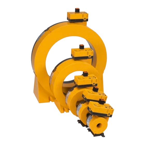
LINETRAXX® CTUB100 series
AC/DC sensitive measuring current transformers (type B)
Intended use
The AC/DC sensitive measuring current transformers
(type B) of the CTUB100 series convert system leakage
and fault currents into an evaluable measurement
signal. The devices are suitable for detecting fault
currents with smooth DC components. They consist
of a CTBC... measuring current transformer core and
a CTUB10... electronic module, which can be combined
to suit the application. The measuring current trans-
formers can be used in DC, AC, and 3(N)AC systems.
The measurement signal is evaluated using devices
of the RCMA4..., RCMS4..., RCMB4... or MRCDB4...
series, respectively EDS440/441-LAB series, to which
the measuring current transformers are connected.
General safety instructions
Part of the device documentation in addition to this
manual is the enclosed "Important safety instructions
for Bender products".
Installation, connection and commissioning are to
be carried out by electrically skilled persons only!
It is essential to follow the existing safety instructions.
I
D
! indicates a high risk of danger that will
anger
result in death or serious injury if not avoided.
I
C
! indicates a low-level risk that can
aution
result in minor or moderate injury or damage
to property if not avoided.
i
This symbol refers to information that is
designed to help you make the best use of
the product.
Overview: Possible combinations of evaluator,
electronic module and measuring current transformer core
Electronic modul
CTUB101
RCMS460/490*
CTUB102
RCMS460/490
CTUB104
EDS440/441-LAB
* Only recommended for retrofit if an AN420 power supply unit is already
available. In this case, if the ready-made connecting cable CTX... is used, the
green plugs of the connecting cable (on the evaluator side) must be removed.
CTUB100-Serie_D00362_05_M_XXEN/11.2023
Evaluator
Meas. current transformer core
RCMA420
CTBC20(P)...60(P)
RCMA423
CTBC20(P)...210(P)
CTBC20(P)...210(P)
CTBC20(P)...210(P)
CTBC20(P)...60(P)
Device features
• Multicolour LED for operation, fault and status
messages
• Electronic module can be exchanged without
mechanical separation of the primary conductors
• Extension/retrofitting or modification of functio-
nalities possible in case of changed monitoring
requirements
• Insensitive to load currents due to full magnetic
shield, can be used for high short-term system-
related load currents (for CTBC...P only).
• Monitoring of the connection to the measuring
current transformer
Connecting cable
CTX... (6 wires)
CTX... (5/6 wires)
CTXS... (4 wires)
Afterwards, the individual conductors must be crimped and connected to the
RCMS460/490 or the AN420. In this case, the conductor "T" is not used
Supply voltage
DC ±12 V
The evaluator supplies the
measuring current transformer.
DC ±12 V
External power supply unit AN420
24 V
External power supply unit
Manual EN
Advertisement
Table of Contents

Related Manuals for Bender LINETRAXX CTUB100 Series


Summary of Contents for Bender LINETRAXX CTUB100 Series
- Page 1 General safety instructions Part of the device documentation in addition to this manual is the enclosed “Important safety instructions for Bender products”. Device features Installation, connection and commissioning are to • Multicolour LED for operation, fault and status...
-
Page 2: Dimension Diagrams
LINETRAXX® CTUB100 series Dimension diagrams Dimensions (mm), Tolerance: ±0.5 mm Type CTUB…-CTBC20(P) ø 20 60,5 – CTUB…-CTBC35(P) ø 35 – CTUB…-CTBC60(P) ø 60 – CTUB…-CTBC120(P) ø 120 CTUB…-CTBC210(P) ø 210 CTUB… – – Mountings (mm) CTBC20(P) 31.4 2 x ø 5.5 CTBC35(P) 49.8 2 x ø... -
Page 3: Device View
LINETRAXX® CTUB100 series Device view CTUB101 CTUB102 CTUB104 Note S1 (k) Connection measuring current transformer core S2 (l) – Not in use – +12 V 24 V 24 V Supply voltage U -12 V – – – – Connection external test a) Offset calibration * Test button T b) Internal functional test **... -
Page 4: Wiring Diagrams
E.01 (CT error) device off and on again If the fault cannot be eliminated, contact Bender Service. Supply voltage U incorrect Apply correct supply voltage U (±12 V or 24 V) -
Page 5: Wiring Diagram
LINETRAXX® CTUB100 series Wiring diagram CTBCx CTBCx CTUB102 CTUB101 CTUB104 S1(k) S2(l) S1(k) S2(l) +12V -12V T 24V GND to the loads to the loads 50 mm 50 mm 2,5 m CTXS-… 2,5 m CTX-… 10 m 10 m 250 mm 250 mm 24V GND RCMS460/490... -
Page 6: Technical Data
LINETRAXX® CTUB100 series Installation instructions measuring current transformer ! Existing protective conductors and aution low-resistance conductor loops must not be routed through the measuring current trans- former! Otherwise, high currents could be in- duced into the conductor loop due to the AC/DC P1 (K): YE P2 (L): GY sensitive measuring technology used. - Page 7 LINETRAXX® CTUB100 series CTBC35 at I ≥ 30 mA ..........125 A 80 A Classification of mechanical conditions acc. to IEC 60721 Δn Stationary use (IEC 60721-3-3) ..........3M11 CTBC35 at I ≥ 300 mA ..........160 A 125 A Δn Transport (IEC 60721-3-2) ............2M4 CTBC35P ..............160 A 160 A Long-term storage (IEC 60721-3-1) .........
-
Page 8: Ordering Details
Alle Rechte vorbehalten. 35305 Grünberg Nachdruck und Vervielfältigung nur mit Germany Genehmigung des Herausgebers. © Bender GmbH & Co. KG, Germany Subject to change! The specified Tel.: +49 6401 807-0 All rights reserved. standards take into account the edition info@bender.de...
Need help?
Do you have a question about the LINETRAXX CTUB100 Series and is the answer not in the manual?
Questions and answers