Table of Contents
Advertisement
Advertisement
Table of Contents

Subscribe to Our Youtube Channel
Summary of Contents for PerkinElmer PTP-1
- Page 1 Peltier Temperature Programmer User’s Guide...
- Page 2 The information contained in this document is subject to change without notice. Except as specifically set forth in its terms and conditions of sale, PerkinElmer makes no warranty of any kind with regard to this document, including, but not limited to, the implied warranties of merchantability and fitness for a particular purpose.
-
Page 3: Table Of Contents
Installation ...................20 Cell Holder Installation ..............21 Connecting a Computer..............26 System Connections................27 Connecting a Flowing Water Source ..........27 Alignment Procedure ..............28 Collecting Reference Spectra with the PTP-1 and PTP-6......29 Description ..................31 Front Panel...................32 Display ..................33 Upper Display ................33 Lower Display ................33 LEDs .....................33... - Page 4 To start a stored cycle ..............45 Remote Control Mode................46 Configuration and Maintenance ............47 Configuration Parameters ..............48 Accessing the parameters ...............48 Setting the parameters ..............48 Calibrating the temperature.............49 Table of parameters ...............50 Maintenance..................51 Cleaning the PTP ................51 Changing the Fuse................52 WEEE Instructions for PerkinElmer Products ..........54...
-
Page 5: Introduction
Introduction... -
Page 6: Introduction
PTP-6 PTP-6+6 In the PTP-1+1 and PTP-6+6, the temperature in the sample cell(s) and the reference cell(s) can be set independently using separate channels on the front panel. Heating and cooling is obtained by thermoelectrical means, the Peltier effect. It is possible, therefore, to study dependences of spectrophotometric properties with temperature and investigate temperature-dependent transitions such as protein denaturation. -
Page 7: Conventions Used
Normal text is used to provide information and instructions. Italic text is used to provide commentary. All eight digit numbers are PerkinElmer part numbers unless stated otherwise. Three terms, in the following standard formats, are also used to highlight special circumstances and warnings. - Page 8 8 . Peltier Temperature Programmer User’s Guide We use the term CAUTION to inform you about situations that could result in serious damage to the instrument or other equipment. CAUTION Details about these circumstances are in a box like this one. Caution (Achtung) Bedeutet, daß...
- Page 9 Introduction . 9 We use the term WARNING to inform you about situations that could result in personal injury to yourself or other persons. Details about these circumstances are in a box like this one. WARNING Warning (Warnung) Bedeutet, daß es bei Nichtbeachten der genannten Anweisung zu einer Verletzung des Benutzers kommen kann.
- Page 10 10 . Peltier Temperature Programmer User’s Guide...
-
Page 11: Warnings And Safety Information
Warnings and Safety Information... -
Page 12: General Operating Conditions
12 . Peltier Temperature Programmer User’s Guide General Operating Conditions This instrument has been designed and tested in accordance with the safety requirements of the International Electrotechnical Commission (IEC). The spectrometer conforms to IEC publication 61010-2-010 (‘Safety requirements for electrical equipment for measurement, control and laboratory use –... -
Page 13: Environmental Conditions
Warnings and Safety Information . 13 Environmental Conditions The instrument has been designed to be safe under the following conditions: • Indoor use; • Altitude up to 2000 m; • Ambient temperatures of 5 C to 40 • A maximum relative humidity of 80% for temperatures up to 31 C, decreasing linearly to 50% relative humidity at 40 •... -
Page 14: Electrical Safety
To ensure satisfactory and safe operation of the PTP it is essential that the green/yellow lead of the line power cable is connected to a true electrical ground. If any part of the PTP is not installed by a PerkinElmer Service Engineer, ensure that the line power plug is correctly wired. -
Page 15: Electrical Protection
Disconnect the instrument from all voltage sources before it is opened for any adjustment, replacement, maintenance or repair. Any adjustment, replacement, maintenance or repair must be carried out by a PerkinElmer Service Engineer or other responsible body who is aware of the hazard involved. -
Page 16: Location And Ventilation
WARNING If any liquid does enter the main body of the PTP, switch off the accessory immediately and make it inoperative. Contact your local PerkinElmer Service Engineer. Make sure that the electricity supply inlets on the instrument are not obstructed i.e. -
Page 17: Emc Compliance
Warnings and Safety Information . 17 EMC Compliance EC directive This instrument has been designed and tested to meet the requirements of the EC Directive 89/336/EEC. The instrument complies with the EMC standard EN 61326-1 (EMC standard for electrical equipment for measurement, control and laboratory use). FCC rules and regulations This product is classified as a digital device used exclusively as industrial, commercial, or medical test equipment. - Page 18 18 . Peltier Temperature Programmer User’s Guide...
-
Page 19: Installation
Installation... -
Page 20: Installation
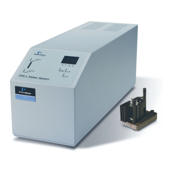
Examine the components for signs of damage in shipment. In the event of damage, file an immediate claim with the authorized carrier and contact your nearest PerkinElmer office or representative. Figure 1 PTP-1 Control Unit and Cell Holder Never connect or disconnect any cables while the spectrometer is switched on. -
Page 21: Cell Holder Installation
Installation . 21 Cell Holder Installation PTP-1 The PTP-1 consists of a single sample cell holder which is installed in the sample beam path in the spectrometer. Before installing the single sample cell holder, remove any accessory currently installed in the sample compartment. - Page 22 Figure 3 Bottom of PTP-1 cell holder with connecting cable attached (Lambda 25) PTP-1+1 The PTP-1+1 consists of a single sample cell holder and a single reference cell holder. The single sample cell holder is installed in the sample beam path in the spectrometer, the single reference cell holder is installed in the reference beam path in the spectrometer.
- Page 23 Installation . 23 Figure 4 Rear of the PTP-1+1 and PTP-6+6 control units PTP-6 The six cell sample holder must be fitted to the baseplate of the cell changer unit in the sample compartment. In a Lambda 25, 35 or 45 spectrometer this is the automatic linear transport (B2000186), while in a Lambda 650, 850 or 950 spectrometer this is the linear cell programmer (B2205401).
- Page 24 24 . Peltier Temperature Programmer User’s Guide Cover screws Figure 5 Six cell holder with cover 2. Remove the cover. The cover must be refitted when the alignment procedure has been completed. 3. Follow the instructions provided with the changer unit to install the six cell holder. The side to which the flat cable will be connected must be placed towards the rear wall of the sample compartment.
- Page 25 Installation . 25 To the PC To the cell holder Figure 6 Rear of the PTP-1 and PTP-6 control units PTP-6+6 The PTP-6+6 consists of a six cell sample holder and a six cell reference holder. The six cell sample holder is installed in the sample beam path in the spectrometer, the six cell reference holder is installed in the reference beam path in the spectrometer.
-
Page 26: Connecting A Computer
26 . Peltier Temperature Programmer User’s Guide 2. Remove the covers. The covers must be refitted when the alignment procedure has been completed. 3. Follow the instructions provided with the changer unit to install the cell holders. The side that the flat cable will be connected to must be placed towards the rear wall of the sample compartment. -
Page 27: System Connections
CAUTION 1. Cut the PVC tube provided into the required number of pieces. For the PTP-1 and PTP-6 you will need two equal lengths of tubing. For the PTP-1+1 and PTP-6+6 you will need 4 equal lengths of tubing. 2. Pass the tubing through the front of the sample compartment and connect it securely to the olives of the heat sinks. -
Page 28: Alignment Procedure
28 . Peltier Temperature Programmer User’s Guide Alignment Procedure Follow the procedure provided in the spectrometer manual and/or changer unit manual to align the cell holders in the light path. NOTE: If aligning the PTP-6 or PTP-6+6 cell holders, replace the metal covers when alignment is complete. -
Page 29: Collecting Reference Spectra With The Ptp-1 And Ptp-6
Installation . 29 Collecting Reference Spectra with the PTP-1 and PTP-6 If the effects of temperature are important in the experiment, you can collect the reference spectrum by running your blank in the same cell that will be used for the sample, and then subtracting from the experimental results. - Page 30 30 . Peltier Temperature Programmer User’s Guide...
-
Page 31: Description
Description... -
Page 32: Front Panel
32 . Peltier Temperature Programmer User’s Guide Front Panel The PTP-1 and PTP-6 have one set of buttons on the front panel that are used to set the temperature in the sample cell holder. The PTP-1+1 and PTP-6+6 control the temperature in the sample cell holder as well as in the reference cell holder, so the front panel on these models has two channels. -
Page 33: Display
Description . 33 Display The display is split into two parts – an Upper display and a Lower display. The numbers in the Upper display are green, while the numbers in the Lower display are red. The status of the PTP, that is RUN or STOP, determines the contents of each display. The exact contents are discussed further in the appropriate sections. -
Page 34: Other Buttons
34 . Peltier Temperature Programmer User’s Guide Other Buttons As well as the split display and the LEDs, the front panel consists of the following buttons: Button Description Increases the stirring rate. As the rate increases, the number of red marks on the indicator bar between the STIRRING MAX and STIRRING MIN buttons increases. -
Page 35: Specification
Description . 35 Specification Temperature Range 0 – 100 Temperature Readout Resolution Temperature Readout Stability + 0.1 Alarms (Cell holder) Alarms to be set for high and low temperature limits through keyboard. Configuration parameters P-01 and P-02 (see page 47). Alarms (Whole system) If the temperature of the heat sink on the cell holder reaches 70... - Page 36 36 . Peltier Temperature Programmer User’s Guide...
-
Page 37: Operation
Operation... -
Page 38: Operation
38 . Peltier Temperature Programmer User’s Guide Operation Consider the boiling points of the solvents used in the experiments. Measurements at high temperatures can produce hazards. WARNING When heated, tightly stoppered cells can produce an overpressure in the cell, and an explosion may result. Temperatures below room temperature can create condensation on the cell windows and thereby affect the accuracy of the measurement. -
Page 39: Switching The Ptp On
Operation . 39 • Due to their principles of operation, Peltier elements require effective heat dissipation on their “warm” side. In the PTP’s cell holders this is achieved through the heatsink, where a stream of water must flow (at least 200 ml/min), if overheating of the cell holder is to be avoided. -
Page 40: Modes Of Operation
40 . Peltier Temperature Programmer User’s Guide Modes of Operation There are two modes of operation – Local control mode and Remote control mode. In Local control mode, control of the PTP is via the front panel of the instrument. In Remote control mode, the instrument is controlled using software on a PC connected to the instrument. -
Page 41: Local Control Mode
Operation . 41 Local Control Mode Starting Temperature Control NOTE: As previously mentioned, it is good practice to allow the system to reach a stable temperature before inserting a sample. Once the temperature is stable, this control can be useful for pre-heating samples before running a cycle. 1. -
Page 42: To Set Up Or Edit A Cycle Program
42 . Peltier Temperature Programmer User’s Guide To set up or edit a cycle program An example is described on page 44. 1. The system must be in STOP status. The display should show C-01, C-02, S.SP or Conf in the Lower display. 2. - Page 43 Operation . 43 9. Press FUNC. The Lower display shows S-02. To add another step to the cycle, repeat the programming from numbered step 6. Set the time to 00.00 to end the program. Up to eight steps can be programmed into a cycle.
-
Page 44: Example
44 . Peltier Temperature Programmer User’s Guide Example The following example starts the samples at room temperature and maintains this for 40 minutes. The program then ramps the samples slowly up to 37 °C and holds for 40 minutes before ramping down to 26 °C, holding for another 40 minutes and then returning to the start of the cycle. -
Page 45: To Start A Stored Cycle
Operation . 45 To start a stored cycle 1. Use the arrow buttons to set the Lower display to C-01 for cycle one or C-02 for cycle two. 2. Press FUNC to start the cycle. The system is now in RUN status. 3. -
Page 46: Remote Control Mode
46 . Peltier Temperature Programmer User’s Guide Remote Control Mode The PTP can also be controlled using the TempLab software, which needs to be installed on a PC connected to the instrument. To setup the method: 1. Select Method from the Application menu or click The TempLab method dialog is displayed. -
Page 47: Configuration And Maintenance
Configuration and Maintenance... -
Page 48: Configuration Parameters
48 . Peltier Temperature Programmer User’s Guide Configuration Parameters Perhaps the most important parameters are the upper and lower temperature limits, as these can be used to limit damage to the sample or equipment and to prevent hazards resulting from heating of the sample. Accessing the parameters 1. -
Page 49: Calibrating The Temperature
Configuration and Maintenance . 49 Calibrating the temperature If the temperature achieved in the cell, measured using a calibrated thermometer, does not match the setpoint read out on the PTP, the temperature can be recalibrated as follows. 1. Using the setpoint control mode (page 41), set the temperature to 0 °C and allow to stabilize. -
Page 50: Table Of Parameters
50 . Peltier Temperature Programmer User’s Guide Table of parameters Number Description P-01 Lower limit of setpoint scale (°C) P-02 Upper limit of setpoint scale (°C) P-03 Offset (°C) P-04 Gain (multiplier) P-05 Dead band (°C) P-06 Proportional band in heating (°C) P-07 Integral action time in heating (seconds) P-08... -
Page 51: Maintenance
Always perform a patch test on an inconspicuous area before you clean the entire accessory. Avoid spilling liquid into the accessory. Clean all external spills immediately. If anything that is spilled enters the main body of the unit, make the PTP inoperative and then contact a PerkinElmer Service Engineer. -
Page 52: Changing The Fuse
52 . Peltier Temperature Programmer User’s Guide Changing the Fuse Disconnect the instrument from the main power supply by unplugging the line power plug from the power module. WARNING 1. Pry open the fuse compartment located at the rear of the PTP (Figure 10) using a screwdriver. - Page 53 Configuration and Maintenance . 53 Figure 11 Location of the voltage indication window on the fuse compartment Figure 12 Fuse block removed from the PTP 3. Ensure that the correct voltage will be displayed in the voltage indication window, and then insert the fuse block (see Figure 11 and Figure 12).
-
Page 54: Weee Instructions For Perkinelmer Products
Customer Care department in your region. http://las.perkinelmer.com/OneSource/Environmental-directives.htm Products from other manufacturers may also form a part of your PerkinElmer system. These other manufacturers are directly responsible for the collection and processing of their own waste products under the terms of the WEEE Directive. Please contact these manufacturers directly before discarding any of their products.
Need help?
Do you have a question about the PTP-1 and is the answer not in the manual?
Questions and answers