Table of Contents
Advertisement
Rev.4 del 01/2011 O.M.A.C. s.r.l.
Operation and Maintenance
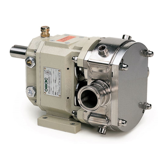
B Series
Lobe Positive Displacement
Group Pump Unit
Translation from the Original Instructions
O.M.M. B SERIES rev.4 01/2011 All rights reserved
O.M.A.C. S.R.L.
O.M.A.C. s.r.l.
1
Via Giovanni Falcone, 8
42048 Rubiera (RE) - Italy
Tel.0522/629371 - 629923 Fax 0522/628980
RUBIERA (RE) - ITALY
E-mail:info@omacpompe.com SitoWeb:www.omacpompe.com
Advertisement
Table of Contents


Need help?
Do you have a question about the B Series and is the answer not in the manual?
Questions and answers