
Related Manuals for LevelOne ProCon GSW-2690


Summary of Contents for LevelOne ProCon GSW-2690
- Page 1 LevelOne GSW-2690 24Fast Ethernet w/2G/2SFP L2 Managed Switch User's Manual User’s Manual Ver: 1.00-0507...
-
Page 2: Table Of Contents
2-1. S 24 F TARTING THERNET 2-1-1. Hardware and Cable Installation ...10 2-1-2. Cabling Requirements... 11 2-1-3. Configuring the Management Agent of 24 Fast Ethernet + 2 Gigabit L2 Managed Switch ...16 2-1-4. IP Address Assignment...20 2-2. T ...25 YPICAL PPLICATIONS OPERATION OF WEB-BASED MANAGEMENT...27... - Page 3 3-12. A LARM ONFIGURATION 3-13. C ... 110 ONFIGURATION 3-13-1. Save/Restore... 111 3-13-2. Config File ... 113 3-14. S ... 114 ECURITY 3-15. B ANDWIDTH ANAGEMENT 3-16. Q UALITY OF ERVICE 3-17. D ...131 IAGNOSTICS 3-18. TFTP S ...134 ERVER 3-19.
-
Page 4: Caution
Caution Circuit devices are sensitive to static electricity, which can damage their delicate electronics. Dry weather conditions or walking across a carpeted floor may cause you to acquire a static electrical charge. To protect your device, always: • Touch the metal chassis of your computer to ground the static electrical charge before you pick up the circuit device. - Page 5 This user’s manual will not only tell you how to install and connect your network system but also configure and monitor the GSW-2690, 24 Fast Ethernet + 2 Gigabit L2 Managed Switch through the built-in CLI and web by RS-232 serial interface and Ethernet ports step-by-step. Many explanations in detail of hardware and software functions are shown as well as the examples of the operation for web- based interface and command-line interface (CLI).
-
Page 6: Introduction
24 Fast Ethernet + 2 Gigabit L2 Managed Switch GSW-2690, 24 Fast Ethernet + 2 Gigabit L2 Managed Switch, implemented 24 10/100Mbps TP + 2 Gigabit ports with TP/SFP, is a standard switch that meets all IEEE 802.3/u/x/z Gigabit, Fast Ethernet and Ethernet specifications. The switch... -
Page 7: User Manual
• Key Features in the Device QoS: Support Quality of Service by the IEEE 802.1P standard. There are two priority queue and packet transmission schedule using Weighted Round Robin (WRR). User-defined weight classification of packet priority can be based on either VLAN tag on packets or user-defined port priority. Spanning Tree: Support IEEE 802.1D, IEEE 802.1w (RSTP: Rapid Spanning Tree Protocol) and IEEE 802.1s (MSTP: Multiple Spanning Tree Protocol) -
Page 8: Checklist
Hardware • Supports 24-port 10/100M TP ports with Nway and auto MDIX function • In 24 Port 10/100Base-TX + 2 Port Gigabit TP/SFP switch, it supports 2 Gigabit dual media ports(TP/SFP) and 2 slots for removable SFP module supporting 1000M SFP fiber module •... - Page 9 • Supports 802.1x port security on a VLAN • Supports user management and only first login administrator can configure the device. The rest of users can only view the switch • SNMP access can be disabled and prevent from illegal SNMP access •...
-
Page 10: View Of 24 Fast Ethernet + 2 Gigabit L2 Managed Switch
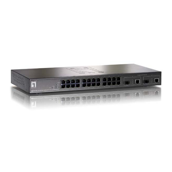
User Manual 1-4. View of 24 Fast Ethernet + 2 Gigabit L2 Managed Switch Fig. 1-1 Full View of GSW-2690 24 Fast Ethernet + 2 Gigabit L2 Managed Switch w/SFP 1-4-1. User Interfaces on the Front Panel (Button, LEDs and Plugs) There are 24 TP Fast Ethernet ports and 2 slots for optional removable modules on the front panel of the switch. - Page 11 • LED Indicators Color System LED CPURUN Green POWER Green Green Green Green 10/100Mbps Ethernet TP Port 1 to 24 LED Green Amber ACT/FDX/ SPD (TP Port 1 to 24 LED) 10/100/1000Mbps Gigabit TP/Fiber Port 25, 26 LED Green Green Green ACT/FDX/ SPD (Port 25,...
-
Page 12: User Interfaces On The Rear Panel
User Manual 1-4-2. User Interfaces on the Rear Panel One RS-232 DB-9 interface is offered for configuration or management. And there is power input socket having switch powered off. Publication date: June, 2005 Revision A1... -
Page 13: View Of The Optional Modules
1-5. View of the Optional Modules In the switch, Port 25, 26 includes two types of media --- TP and SFP Fiber (LC, BiDi LC…); this port supports 10/100/1000Mbps TP or 1000Mbps SFP Fiber with auto-detected function. 1000Mbps SFP Fiber transceiver is used for high- speed connection expansion;... -
Page 14: Installation
User Manual 2. Installation 2-1. Starting 24 Fast Ethernet + 2 Gigabit L2 Managed Switch Up This section will give users a quick start for: Hardware and Cable Installation - Management Station Installation - Software booting and configuration 2-1-1. Hardware and Cable Installation At the beginning, please do first: ⇒... -
Page 15: Cabling Requirements
It means you do not have to tell from them, just plug it. ⇒ Use Cat. 5 grade RJ-45 TP cable to connect to a TP port of the switch and the other end is connected to a network-aware device such as a workstation or a server. - Page 16 User Manual 2-1-2-1. Cabling Requirements for TP Ports ⇒ For Fast Ethernet TP network connection The grade of the cable must be Cat. 5 or Cat. 5e with a maximum length of 100 meters. ⇒ Gigabit Ethernet TP network connection ...
- Page 17 If more than two switches are connected in the same network, select one switch as Level 1 switch and connect all other switches to it at Level 2. Server/Host is recommended to connect to the Level 1 switch.
- Page 18 User Manual Case1: All switch ports are in the same local area network. Every port can access each other (See Fig. 2-2). Fig. 2-2 No VLAN Configuration Diagram If VLAN is enabled and configured, each node in the network that can communicate each other directly is bounded in the same VLAN area.
- Page 19 Case 2b: Port-based VLAN (See Fig.2-4). Fig. 2-4 Port-based VLAN Diagram 1. VLAN1 members could not access VLAN2, VLAN3 and VLAN4 members. 2. VLAN2 members could not access VLAN1 and VLAN3 members, but they could access VLAN4 members. VLAN3 members could not access VLAN1, VLAN2 and VLAN4. 4.
-
Page 20: Configuring The Management Agent Of 24 Fast Ethernet + 2 Gigabit L2 Managed Switch
2-1-3. Configuring the Management Agent of 24 Fast Ethernet + 2 Gigabit L2 Managed Switch We offer you three ways to startup the switch management function. They are RS-232 console, CLI, and Web. Users can use any one of them to monitor and configure the switch. - Page 21 RS-232 cable with DB-9 connector. Next, run a terminal emulator with the default setting of the switch’s serial port. With this, you can communicate with the switch. In the switch, RS-232 interface only supports baud rate 57.6k bps with 8 data bits, 1 stop bit, no parity check and no flow control.
- Page 22 Please refer to Fig. 2-6 Console Management for details about the ex-factory setting. They are default setting of IP address. You can first either configure your PC IP address or change IP address of the switch, next to change the IP address of default gateway and subnet mask.
- Page 23 IP address or to know the IP address of the switch. Then, follow the procedures listed below. 1. Set up a physical path between the configured the switch and a PC by a qualified UTP Cat. 5 cable with RJ-45 connector.
-
Page 24: Ip Address Assignment
User Manual Fig. 2-9 the Login Screen for Web 2-1-4. IP Address Assignment For IP address configuration, there are three parameters needed to be filled in. They are IP address, Subnet Mask, Default Gateway and DNS. IP address: The address of the network device in the network is used for internetworking communication. - Page 25 With the classful addressing, it divides IP address into three classes, class A, class B and class C. The rest of IP addresses are for multicast and broadcast. The bit length of the network prefix is the same as that of the subnet mask and is denoted as IP address/X, for example, 192.168.1.0/24.
- Page 26 User Manual Class D and E: Class D is a class with first 4 MSB (Most significance bit) set to 1-1-1-0 and is used for IP Multicast. See also RFC 1112. Class E is a class with first 4 MSB set to 1-1-1-1 and is used for IP broadcast.
- Page 27 In this diagram, you can see the subnet mask with 25-bit long, 255.255.255.128, contains 126 members in the sub-netted network. Another is that the length of network prefix equals the number of the bit with 1s in that subnet mask. With this, you can easily count the number of IP addresses matched.
- Page 28 Basically, it is a routing policy. The gateway setting is used for Trap Events Host only in the switch. For assigning an IP address to the switch, you just have to check what the IP address of the network will be connected with the switch. Use the same network address and append your host address to it.
-
Page 29: Typical Applications
Central Site Fig. 2-12 Network Connection between Remote Site and Central Site Fig. 2-12 is a system wide basic reference connection diagram. This diagram demonstrates how the switch connects with other network devices and hosts. User Manual Publication date: June, 2005... - Page 30 User Manual Fig. 2-13 Office Network Connection Publication date: June, 2005 Revision A1...
-
Page 31: Operation Of Web-Based Management
2 Gigabit dual media ports with TP/SFP Fiber management Ethernet switch. With this facility, you can easily access and monitor through any one port of the switch all the status of the switch, including MIBs status, each port activity, Spanning tree status, port aggregation status, multicast traffic, VLAN and priority status, even illegal access record and so on. - Page 32 If there are two or more users using administrator’s identity, the switch will allow the only one who logins first to configure the system. The rest of users, even with administrator’s identity, can only monitor the system.
-
Page 33: Web Management Home Overview
• The Information of Page Layout On the top side, it shows the front panel of the switch. In the front panel, the linked ports will display green; as to the ports, which are link off, they will be dark. - Page 34 User Manual In Fig. 3-3, it shows the basic information of the clicked port. With this, you’ll see the information about the port status, traffic status and bandwidth rating for egress and ingress respectively. On the left-top corner, there is a pull-down list for Auto Logout. For the sake of ...
- Page 35 Root System SNMP IGMP Snooping MAC Table 802.1x Configuration Bandwidth Diagnostics Reboot User Manual Port DHCP Boot VLAN GVRP Trunk Alarm Security TFTP Server Firmware Upgrade Logout Publication date: June, 2005 Revision A1...
-
Page 36: System Information
The time accumulated since this switch is powered up. Its format is day, hour, minute, second. Current time: Show the system time of the switch. Its format: day of week, month, day, hours : minutes : seconds, year. For instance, Tue Apr 20 23:25:58 2005 BIOS version: The version of the BIOS in this switch. - Page 37 Host IP address: The IP address of the switch. Host MAC address: It is the Ethernet MAC address of the management agent in this switch. Device Port: Show all types and numbers of the port in the switch. RAM size: The size of the DRAM in this switch.
-
Page 38: Ip Configuration
The switch supports both manual IP address setting and automatic IP address setting via DHCP server. When IP address is changed, you must reboot the switch to have the setting taken effect and use the new IP to browse for web management and CLI management. - Page 39 IP address: Users can configure the IP settings and fill in new values if users set the DHCP function “Disable”. Then, click <Apply> button to update. When DHCP is disabled, Default: 192.168.1.1 If DHCP is enabled, this field is filled by DHCP server and will not allow user manually set it any more.
- Page 40 The switch supports DNS client function to re-route the mnemonic name address to DNS server to get its associated IP address for accessing Internet. User can specify a DNS IP address for the switch. With this, the switch can translate a mnemonic name address into an IP address.
-
Page 41: Time Configuration
“Minute” and “Second” within the valid value range indicated in each item. If you input an invalid value, for example, 61 in minute, the switch will clamp the figure to NTP is a well-known protocol used to synchronize the clock of the switch system time over a network. - Page 42 Greenwich Mean Time (GMT). If use the NTP mode and select a built-in NTP time server or manually specify an user-defined NTP server as well as Time Zone, the switch will sync the time in a short after pressing <Apply> button. Though it synchronizes the time automatically, NTP does not update the time periodically without user’s processing.
- Page 43 Day Light Saving End : This is used to set when to stop performing the daylight saving time. Mth: Range is 1 ~ 12. Default: 1 Day: Range is 1 ~ 31. Default: 1 Hour: Range is 0 ~ 23. Default: 0 Fig.
-
Page 44: Account Configuration
User Manual 3-1-4. Account Configuration In this function, only administrator can create, modify or delete the username and password. Administrator can modify other guest identities’ password without confirming the password but it is necessary to modify the administrator-equivalent identity. Guest-equivalent identity can modify his password only. Please note that you must confirm administrator/guest identity in the field of Authorization in advance before configuring the username and password. -
Page 45: Management Security
3-1-5. Management Security Through the management security configuration, the manager can do the strict setup to control the switch and limit the user to access this switch. The following rules are offered for the manager to manage the switch: Rule 1) : When no lists exists, then it will accept all connections. - Page 46 VLAN VID is able to be accepted or denied by the switch, the IP range of the user could be accepted or denied by the switch, the port that the user is allowed or not allowed to connect with the switch, or the way of controlling and connecting to the switch via Http, Telnet or SNMP.
- Page 47 The switch including “Any” and “Custom”. Default is “Any”. “Http”, “Telnet” and “SNMP” are three ways for the access and managing the switch in case that” Custom” had been chosen. Action: supports two kinds of options The switch including “Deny”...
-
Page 48: Virtual Stack
Master machine. Instead of SNMP or Telnet UI, VSM is only available in Web UI. While one switch become the Master, two rows of buttons for group device will appear on the top of its Web UI. - Page 49 It is used for the activation or de-activation of VSM. Default is Enable. Role: The role that the switch would like to play in virtual stack. Two types of roles, including master and slave are offered for option. Default is Master.
-
Page 50: Port Configuration
User Manual 3-2. Port Configuration Four functions, including Port Status, Port Configuration, Simple Counter and Detail Counter are contained in this function folder for port monitor and management. Each of them will be described in detail orderly in the following sections. - Page 51 Port Status Function Description: Report the latest updated status of all ports in this switch. When any one of the ports in the switch changes its parameter displayed in the page, it will be automatically refreshed the port current status about every 5 seconds.
- Page 52 User Manual Speed / Duplex : Display the speed and duplex of all port. There are three speeds 10Mbps, 100Mbps and 1000Mbps supported for TP media, and the duplex supported is half duplex and full duplex. If the media is 1Gbps fiber, it is 1000Mbps supported only.
- Page 53 Parameter description of Port 25 and Port26: Connector Type: Display the connector type, for instance, UTP, SC, ST, LC and so Fiber Type: Display the fiber mode, for instance, Multi-Mode, Single-Mode. Tx Central Wavelength: Display the fiber optical transmitting central wavelength, for instance, 850nm, 1310nm, 1550nm and so on.
- Page 54 User Manual Vendor SN (Serial Number): Show the serial number assigned by the manufacturer. Date Code: Show the date this module was made. Temperature: Show the current temperature of module. Vcc: Show the working DC voltage of module. Mon1(Bias) mA: Show the Bias current of module.
-
Page 55: Port Configuration
Function name: Port Configuration Function description: It is used to set each port’s operation mode. The switch supports 3 parameters for each port. They are State, Speed/Duplex and Flow Control. Parameter description: State: Set the communication capability of the port is Enabled or Disabled. - Page 56 User Manual Speed/Duplex: Set the speed and duplex of the port. In speed, 10/100Mbps baud rate is available for Fast Ethernet, Gigabit module in port 25, 26. If the media is 1Gbps fiber, it is always 1000Mbps and the duplex is full only. If the media is TP, the Speed/Duplex is comprised of the combination of speed mode, 10/100/1000Mbps, and duplex mode, full duplex and half duplex.
-
Page 57: Simple Counter
3-2-3. Simple Counter The function of Simple Counter collects any information and provides the counting about the traffic of the port, no matter the packet is good or bad. In the Fig. 3-10, the window can show all ports’ counter information at the same time. - Page 58 User Manual Rx Packet: The counting number of the packet received. Tx Collision: Number of collisions transmitting frames experienced. Rx Error Packet: Number of bad packets received. Publication date: June, 2005 Revision A1...
-
Page 59: Detail Counter
3-2-4. Detail Counter The function of Detail Counter collects any information and provides the counting about the traffic of the port, no matter the packet is good or bad. In the Fig. 3-14, the window can show only one port counter information at the same time. - Page 60 User Manual Rx Unicast Packets: Show the counting number of the received unicast packet. Rx Broadcast Packets: Show the counting number of the received broadcast packet. Rx Multicast Packets: Show the counting number of the received multicast packet. Rx Pause Packets: Show the counting number of the received pause packet.
- Page 61 Packets 512-1023 Octets: Number of 512 ~ 1023-byte frames in good and bad packets received. Packets 1024- 1522 Octets: Number of 1024-1522-byte frames in good and bad packets received. Tx Packets: The counting number of the packet transmitted. TX Octets: Total transmitted bytes.
-
Page 62: Snmp Configuration
Basically, it is passive except issuing the trap information. The switch supports a switch to turn on or off the SNMP agent. If you set the field SNMP “Enable”, SNMP agent will be started up. All supported MIB OIDs, including RMON MIB, can be accessed via SNMP manager. - Page 63 Default port number :162 Trap: In the switch, there are four trap hosts supported. Each of them has its own community name and IP address; is user-definable. To set up a trap host means to create a trap manager by assigning an IP address to host the trap message.
-
Page 64: Dhcp Boot
At this moment, a bunch of switch or other network device on the LAN will try its best to find the server to get the services or try to set up the predefined links, they will issue many broadcast packets in the network. -
Page 65: Igmp Snooping
IP multicast packets are running over the network. This is because a switch that does not support IGMP or IGMP Snooping can not tell the multicast packet from the broadcast packet, so it can only treat them all as the broadcast packet. - Page 66 Passive: In Passive Snooping mode, the IGMP snooping will not periodically poll the hosts in the groups. The switch will send a Membership Query message to all hosts only when it has received a Membership Query message from a router.
-
Page 67: Vlan
1, you can communicate with port 2&3&4. If you are on the port 5, then you cannot talk to them. Each port-based VLAN you built up must be assigned a group name. This switch can support up to maximal 26 port-based VLAN groups. - Page 68 Note: If Symmetric is enabled and port 1, for example, receives an untagged packet, the switch will apply the PVID of port 1 to tag this packet, the packet then will be forwarded. But if the PVID of port 1 is not 100, the packet will be dropped.
-
Page 69: Tag-Based Group
3-6-2. Tag-based Group Function name: Tag-based Group Configuration Function description: It shows the information of existed Tag-based VLAN Groups. You can also easily create, edit and delete a Tag-based VLAN group by pressing <Add>, <Edit> and <Delete> function buttons. User can add a new VLAN group by inputting a new VLAN name and VLAN ID after pressing <Add>... - Page 70 User Manual Add Group: Input the VLAN name, VID and then choose the member by ticking the check box beside the port No. to create a new Tag-based VLAN. As to the parameter of Untag, it stands for an egress rule of the port. If you tick the check box beside the port No., packets with this VID outgoing from this port will be untagged.
-
Page 71: Pvid
Tag-based VLAN with VID x. For example, if port x receives an untagged packet, the switch will apply the PVID (assume as VID y) of port x to tag this packet, the packet then will be forwarded as the tagged packet with VID y. -
Page 72: Port-Based Group
User Manual 3-6-4. Port-based Group Function name: Port-based Group Configuration Function description: It shows the information of the existed Port-based VLAN Groups. You can easily create, edit and delete a Port-based VLAN group by pressing <Add>, <Edit> and <Delete> function buttons. User can add a new VLAN group by inputting a new VLAN name. - Page 73 Add Group: Create a new Port-based VLAN. Input the VLAN name and choose the member by ticking the check box beside the port No., then, press the <Apply> button to have the setting taken effect. Delete Group: Just press the <Delete> button to remove the selected group entry from the Port-based group table.
-
Page 74: Mac Table
User Manual 3-7. MAC Table MAC Table Configuration gathers many functions, including MAC Table Information, MAC Table Maintenance, Static and MAC Alias, which cannot be categorized to some function type. They are described below. Function name: MAC Table Information Function Description: Display the static or dynamic learning MAC entry and the state for the selected port. - Page 75 Port: The port that exists in the searched MAC Entry. VID: VLAN Group that MAC Entry exists. State: Display the method that this MAC Entry is built. It may show “Dynamic MAC” or “Static MAC”. User Manual Fig. 3-26 Publication date: June, 2005 Revision A1...
- Page 76 User Manual Function Name: MAC Table Maintenance Function Description: This function can allow the user to set up the processing mechanism of MAC Table. An idle MAC address exceeding MAC Address Age-out Time will be removed from the MAC Table. The range of Age-out Time is 10-1000000 seconds, and the setup of this time will have no effect on static MAC addresses.
- Page 77 As “static” is chosen, assign a MAC address to a specific port, all of the switch’s traffics sent to this MAC address will be forwarded to this port. As “static with destination drop” is chosen, the packet will be dropped if its DA is equal to the value you set up.
- Page 78 While the SA of the incoming packets meets the value you set up, these packets will be dropped. Port : Select the port No. you would like to do setup in the switch. It is 1 ~26. Publication date: June, 2005 Revision A1...
- Page 79 Function name: MAC Alias Function description: MAC Alias function is used to let you assign MAC address a plain English name. This will help you tell which MAC address belongs to which user in the illegal access report. At the initial time, it shows all pairs of the existed alias name and MAC address.
- Page 80 User Manual Parameter description: MAC Address: It is a six-byte long Ethernet hardware address and usually expressed by hex and separated by hyphens. For example, 00 – 11 - 6B - D6 – 00 - 02 Alias: MAC alias name you assign. Note: If there are too many MAC addresses learned in the table, we recommend you inputting the MAC address and alias name directly.
-
Page 81: Gvrp Configuration
3-8. GVRP Configuration GVRP is an application based on Generic Attribute Registration Protocol (GARP), mainly used to automatically and dynamically maintain the group membership information of the VLANs. The GVRP offers the function providing the VLAN registration service through a GARP application. It makes use of GARP Information Declaration (GID) to maintain the ports associated with their attribute database and GARP Information Propagation (GIP) to communicate among switches and end stations. - Page 82 A time period for announcement that all registered device is going to be de-registered. If someone still issues a new join, then a registration will be kept in the switch. Valid range: 1000-5000 unit time, Default: 1000 unit time. Default Applicant Mode: The mode here means the type of participant.
- Page 83 GVRP PDU. There are two modes, disable and enable, provided for the user’s choice. Disabled: In this mode, the switch dynamic VLAN will be created when this port received GVRP PDU. The default setting is Normal. Enabled: In this mode, the switch does not create dynamic VLAN when this port received GVRP PDU.
- Page 84 User Manual Function name: GVRP Counter Function description: All GVRP counters are mainly divided into Received and Transmitted two categories to let you monitor the GVRP actions. Actually, they are GARP packets. Parameter description: Received: Total GVRP Packets: Total GVRP BPDU is received by the GVRP application. Invalid GVRP Packets: Number of invalid GARP BPDU is received by the GARP application.
- Page 85 LeaveEmpty Message Packets: Number of GARP BPDU with Leave Empty message is received by the GARP application. Empty Message Packets: Number of GARP BPDU with Empty message is received by the GARP application. Transmitted: Total GVRP Packets: Total GARP BPDU is transmitted by the GVRP application. Invalid GVRP Packets: Number of invalid GARP BPDU is transmitted by the GVRP application.
- Page 86 User Manual Function name: GVRP Group Information Function description: To show the dynamic group member and their information. Parameter description: Current Dynamic Group Number: The number of GVRP group that are created currently. VID: VLAN identifier. When GVRP group creates, each dynamic VLAN group owns its VID.
-
Page 87: Stp Configuration
Bridge Priority: Show this switch’s current bridge priority setting. Default is 32768. Designated Root: Show root bridge ID of this network segment. If this switch is a root bridge, the “Designated Root” will show this switch’s bridge ID. Designated Priority: Show the current root bridge priority. - Page 88 User Manual All bridges in the LAN will re-learn and determine which the root bridge is. Maximum Age time is assigned by root bridge in unit of seconds. Default is 20 seconds. Current Forward Delay: Show the current root bridge forward delay time. The value of Forward Delay time is set by root.
-
Page 89: Stp Configuration
Function description: User can set the following Spanning Tree parameters to control STP function enable/disable, select mode RSTP/STP and affect STP state machine behavior to send BPDU in this switch. The default setting of Spanning Tree Protocol is “Disable”. Parameter description: Spanning Tree Protocol: Set 802.1W Rapid STP function Enable / Disable. - Page 90 Two options are offered for the user’s choosing STP algorithm. One is RSTP and the other is STP. If STP is chosen, RSTP will run as a legacy STP. The switch supports RSTP (802.1w) which is backward compatible with STP (802.1d).
-
Page 91: Stp Port Configuration
Root Port more possibly. Configured Path Cost: The range is 0 – 200,000,000. In the switch, if path cost is set to be zero, the STP will get the recommended value resulted from auto-negotiation of the link accordingly and display this value in the field of Path Cost Status. - Page 92 User Manual 802.1w RSTP recommended value: (Valid range: 1 – 200,000,000) 10 Mbps : 2,000,000 100 Mbps : 200,000 1 Gbps Default: 0 Priority: Priority here means Port Priority. Port Priority and Port Number are mixed to form the Port ID. Port IDs are often compared in order to determine which port of a bridge would become the Root Port.
- Page 93 User Manual M Check: Migration Check. It forces the port sending out an RSTP BPDU instead of a legacy STP BPDU at the next transmission. The only benefit of this operation is to make the port quickly get back to act as an RSTP port. Click <M Check>...
-
Page 94: Trunking Configuration
As to system restrictions about the port aggregation function on the switch, In the management point of view, the switch supports maximum 3 trunk groups for LACP and additional 3 trunk groups for Static Trunk. But in the system capability view, only 3 “real trunked”... - Page 95 Per Trunking Group supports a maximum of 4 ready member-ports. Please note that some decisions will automatically be made by the system while you are configuring your trunking ports. Trunk Setting Rules are listed below: Rule1: Maximum 3 groups are allowed Rule 2: The members of each group cannot exceed more than 4 ports Rule 3: Group 1 and 2 cannot exist member 25 and 26 port Rule 4: Group 3 cannot exist member from 1 to 24 port...
- Page 96 Function name: Port Setting/Status Function description: Port setting/status is used to configure the trunk property of each and every port in the switch system. Parameter description: Method: This determines the method a port uses to aggregate with other ports. None: A port does not want to aggregate with any other port should choose this default setting.
- Page 97 Aggtr: Aggtr is an abbreviation of “aggregator”. Every port is also an aggregator, and its own aggregator ID is the same as its own Port No. We can regard an aggregator as a representative of a trunking group. Ports with same Group ID and using same trunking method will have the opportunity to aggregate to a particular aggregator port.
- Page 98 User Manual Function name: Aggregator View Function description: To display the current port trunking information from the aggregator point of view. Parameter description: Aggregator: It shows the aggregator ID (from 1 to 26) of every port. In fact, every port is also an aggregator, and its own aggregator ID is the same as its own Port No..
- Page 99 LACP Detail (LACP Aggregator Detailed Information) Function description: Show the detailed information of the LACP trunking group. Parameter description: Actor: The switch you are watching on. Partner: The peer system from this aggregator’s view. System Priority: Show the System Priority part of a system ID.
- Page 100 Default: 32768. LACP Hash Method: DA+SA, DA and SA are three Hash methods offered for the Link Aggregation of the switch. Packets will decide the path to transmit according to the mode of Hash you choose. Default: DA and SA...
-
Page 101: Configuration
3-11. 802.1x Configuration 802.1x port-based network access control provides a method to restrict users to access network resources via authenticating user’s information. This restricts users from gaining access to the network resources through a 802.1x-enabled port without authentication. If a user wishes to touch the network through a port under 802.1x control, he (she) must firstly input his (her) account name for authentication and waits for gaining authorization before sending or receiving any packets from a 802.1x-enabled port. - Page 102 PC A, then, is allowed to access B and C via the switch. If there are two switches directly connected together instead of single one, for the link connecting two switches, it may have to act two port roles at the end of the link: authenticator and supplicant, because the traffic is bi-directional.
- Page 103 EAPOL and the left side is EAP. At the initial stage, the supplicant A is unauthenticated and a port on switch acting as an authenticator is in unauthorized state. So the access is blocked in this stage.
- Page 104 User Manual If user ID and password is correct, the authentication server will send a Radius-Access-Accept to the authenticator. If not correct, the authentication server will send a Radius-Access-Reject. When the authenticator PAE receives a Radius-Access-Accept, it will send an EAP-Success to the supplicant. At this time, the supplicant is authorized and the port connected to the supplicant and under 802.1x control is in the authorized state.
- Page 105 Only MultiHost 802.1X is the type of authentication supported in the switch. In this mode, for the devices connected to this port, once a supplicant is authorized, the devices connected to this port can access the network resource through this port.
- Page 106 User Manual Function name: 802.1x State Setting Function description: This function is used to configure the global parameters for RADIUS authentication in 802.1x port security application. Parameter description: Radius Server: RADIUS server IP address for authentication. Default: 192.168.1.1 Port Number: The port number to communicate with RADIUS server for the authentication service.
- Page 107 Function name: 802.1x Mode Setting Function description: Set the operation mode of 802.1X for each port. In this device, it supports only Multi-host operation mode. Parameter description: Port Number: Indicate which port is selected to configure the 802.1x operation mode. 802.1x Mode: 802.1x operation mode.
- Page 108 User Manual Function name: Port Security Management Function description: Shows each port status. In Multihost mode, it shows the port number and its status, authorized or unauthorized. Parameter description: Disable Mode: When selecting Disable mode for a port in the function 802.1X Port Mode Configuration, the port is in the uncontrolled port state and does not apply 802.1X authenticator on it.
- Page 109 Function name: Param. Setting Function description: This function is used to configure the parameters for each port in 802.1x port security application. Refer to the following parameters description for details. Parameter description: Port: It is the port number to be selected for configuring its associated 802.1x parameters which are Port control, reAuthMax, txPeriod, Quiet Period, reAuthEnabled, reAuthPeriod, max.
- Page 110 User Manual reAuthEnabled: Choose whether regular authentication will take place in this port. Default: ON reAuthPeriod(1-65535 s): A non-zero number seconds between the periodic re-authentication of the supplicant. Default: 3600 max. Request(1-10): The maximum of number times that the authenticator will retransmit an EAP Request to the supplicant before it times out the authentication session.
-
Page 111: Alarm Configuration
These trap functions are as they describe. The special one is Module Swap. It means that when the switch detects a module with the different module ID to be inserted, the switch treats it as Module swapped. The traps that the switch supports are listed below. - Page 112 User Manual Function name: Email/SMS Configuration Function description: Alarm configuration is used to configure the persons who should receive the alarm message via either email or SMS, or both. It depends on your settings. An email address or a mobile phone number has to be set in the web page of alarm configuration (See Fig.
- Page 113 Parameter description: Email: Mail Server: the IP address of the server transferring your email. Username: your username on the mail server. Password: your password on the mail server. Email Address 1 – 6: email address that would like to receive the SMS: SMS Server: the IP address of the server transferring your SMS.
-
Page 114: Configuration
User Manual 3-13. Configuration The switch supports three copies of configuration, including the default configuration, working configuration and user configuration for your configuration management. All of them are listed and described below respectively. Default Configuration: This is the ex-factory setting and cannot be altered. -
Page 115: Save/Restore
3-13-1. Save/Restore Function name: Save As Start Configuration Function description: Save the current configuration as a start configuration file in flash memory. Function name: Save As User Configuration Function description: Save the current configuration as a user configuration file in flash memory. User Manual Fig. - Page 116 User Manual Function name: Restore Default Configuration Function description: Restore Default Configuration function can retrieve the ex-factory setting to replace the start configuration. Function name: Restore User Configuration Function description: Restore User Configuration function can retrieve the previous confirmed working configuration stored in the flash memory to update start configuration. When completing to restore the configuration, the system’s start configuration is updated and will be changed its system settings after rebooting the system.
-
Page 117: Config File
3-13-2. Config File Function name: Config File Function description: With this function, user can back up or reload the config files of Save As Start or Save As User via TFTP. Parameter description: Export File Path: Export Start: Export Save As Start’s config file stored in the flash. Export User-Conf: Export Save As User’s config file stored in the flash. -
Page 118: Security
User Manual 3-14. Security Function name: Mirror Configuration Function description: Mirror Configuration is to monitor the traffic of the network. For example, we assume that Port A and Port B are Monitoring Port and Monitored Port respectively, thus, the traffic received by Port B will be copied to Port A for monitoring. - Page 119 Port 1~26. In this group, all of these member ports cannot forward packets with each other. Thus, the switch will not be capable of forwarding any packets in case its all ports become the members of the Isolated group.
- Page 120 User Manual Function name: Restricted Group Function description: The function of the Restricted Group can decide the direction of transmitting packets for the specific port. The packets received by the port with the “Ingress” mode of Restricted Group will be sent to the ports with the “Egress” mode of Restricted Group.
-
Page 121: Bandwidth Management
3-15. Bandwidth Management Function name: Ingress Bandwidth Setting Function description: Ingress Bandwidth Setting function is used to set up the limit of Ingress bandwidth for each port. Parameter description: Port No.: Choose the port that you would like this function to work on it. Valid range of the port is 1~26. - Page 122 User Manual Function name: Egress Bandwidth Setting Function description: Egress Bandwidth Setting function is used to set up the limit of Egress bandwidth for each port. Parameter description: Port No.: Choose the port that you would like this function to work on it. Valid range of the port is 1~26.
- Page 123 Function name: Storm Setting Function description: Bandwidth Management function is used to set up the limit of Ingress and Egress bandwidth for each port. Parameter description: Storm Type: Disable: Disable the function of the bandwidth storm control. Broadcast Storm Control: Enable the function of bandwidth storm control for broadcast packets.
- Page 124 User Manual Storm Rate : Set up the limit of bandwidth for storm type you choose. Valid value of the storm rate ranges from 1-100 with the minimum unit of 1. And only integer is acceptable. Default is 100. Publication date: June, 2005 Revision A1...
-
Page 125: Qos(Quality Of Service) Configuration
Priority, IP TOS Priority, and DiffServ DSCP Priority. Port Based Priority has a special name called VIP Port in the switch. Any packets enter VIP Port will have highest transmitting priority. MAC Priority act on the destination address of MAC in packets. - Page 126 User Manual The QoS functions as we mentioned above are able to enabled at the same time. But, the following precedence will decide whether these functions work or not. 1. enable both VIP and TOS Choose priorities of VIP and TOS. 2.
- Page 127 Function name: QoS Global Setting Function description: When you want to use QoS function, please enable QoS Mode in advance. Then you can use MAC Priority, 802.1p Priority, IP TOS Priority, DiffServ DSCP Priority, or VIP Port functions and take effect. In this function, you can Enable QoS Mode.
- Page 128 User Manual Function name: VIP Port Setting Function description: When the port is set as VIP Port, the packets enter this port and will have highest transmitting priority. For example, as you choose port 2 is VIP Port, simultaneously transmit packets from port 2 and port 3 to port 1 at speed of 100MB and let congestion happen.
- Page 129 Function description: This function will affect the priority of VLAN tag. Based on priority of VLAN tag, it can arrange 0~8 priorities, priorities can map to 4 queues of the switch (queue 0~3) and possess different bandwidth distribution according to your weight setting.
- Page 130 PRECEDENCE 3-bits can arrange 8 kinds of priorities corresponding to the 0~7 priority in the following priority diagram. TOS Delay Priority Mapping works while D-TYPE in TOS field of IP header of the packets received by the switch is configured. Parameter description: TOS Delay Priority Mapping: Each Priority can select any of Queue 0 ~ Queue 3.
- Page 131 PRECEDENCE 3-bits can arrange 8 kinds of priorities corresponding to the 0~7 priority in the following priority diagram. TOS Delay Priority Mapping works while T-TYPE in TOS field of IP header of the packets received by the switch is configured. Parameter description: TOS Throughput Priority Mapping: Each Priority can select any of Queue 0 ~ Queue 3.
- Page 132 PRECEDENCE 3-bits can arrange 8 kinds of priorities corresponding to the 0~7 priority in the following priority diagram. TOS Delay Priority Mapping works while R-TYPE in TOS field of IP header of the packets received by the switch is configured. Parameter description: TOS Reliability Priority Mapping: Each Priority can select any of Queue 0 ~ Queue 3.
- Page 133 PRECEDENCE 3-bits can arrange 8 kinds of priorities corresponding to the 0~7 priority in the following priority diagram. TOS Delay Priority Mapping works while M-TYPE in TOS field of IP header of the packets received by the switch is configured. Parameter description: TOS Reliability Priority Mapping: Each Priority can select any of Queue 0 ~ Queue 3.
- Page 134 DSCP can form total 64 (0~63) kinds of Traffic Class based on the arrangement of 6-bit field in DSCP of the IP packet. In the switch, user is allowed to set up these 64 kinds of Class that belong to any of queue 0~3.
-
Page 135: Diagnostics
3-17. Diagnostics Three functions, including Diagnostics, Loopback Test and Ping Test are contained in this function folder for device self-diagnostics. Each of them will be described in detail orderly in the following sections. Diagnostics Function name: Diagnostics Function description: Diagnostics function provides a set of basic system diagnosis. It let users know that whether the system is health or needs to be fixed. - Page 136 The test signal only wraps around in the switch box. As to the latter test function, it will send the test signal to its link partner. If you do not have them connected to active network devices, i.e.
- Page 137 Ping Test function to let you know that if the target device is available or not. You can simply fill in a known IP address and then click <Ping> button. After a few seconds later, the switch will report you the pinged device is alive or dead in the field of Ping Result.
-
Page 138: Tftp Server
User Manual 3-18. TFTP Server Function name: TFTP Server Function description: Set up IP address of TFTP server. Parameter description: Specify the IP address where the TFTP server locates. Fill in the IP address of your TFTP server, then press <Apply> button to have the setting taken effect. Publication date: June, 2005 Revision A1 Fig. -
Page 139: Log
This function shows the log data. The switch provides system log data for users. There are 16 private trap logs, 5 public trap logs. The switch supports total 120 log entries. For more details on log items, please refer to the section of Trap/Alarm Configuration and SNMP Configuration. - Page 140 User Manual Upload Log: Upload log data through tftp. Clear Log: Clear log data. Publication date: June, 2005 Revision A1...
-
Page 141: Firmware Upgrade
3-20. Firmware Upgrade Software upgrade tool is used to help upgrade the software function in order to fix or improve the function. The switch provides a TFTP client for software upgrade. This can be done through Ethernet. Function name: Firmware Upgrade Function description: The switch supports TFTP upgrade tool for upgrading software. -
Page 142: Reboot
Function name: Reboot Function description: Reboot the switch. Reboot takes the same effect as the RESET button on the front panel of the switch. It will take around thirty (30) seconds to complete the system boot. Parameter description: Save and Reboot: Save the current settings as start configuration before rebooting the switch. -
Page 143: Logout
Logout Function description: The switch allows you to logout the system to prevent other users from the system without the permission. If you do not logout and exit the browser, the switch will automatically have you logout. Besides this manually logout and implicit logout, you can pull down the <Auto Logout>... -
Page 144: Operation Of Cli Management
-- Locate the correct DB-9 null modem cable with female DB-9 connector. Null modem cable comes with the management switch. Refer to the Appendix B for null modem cable configuration. -- Attach the DB-9 female connector to the male DB-9 serial port connector on the Management board. - Page 145 User Manual Fig. 4-1 Fig. 4-2 Publication date: June, 2005 Revision A1...
-
Page 146: Commands Of Cli
User Manual 4-2. Commands of CLI To see the commands of the mode, please input “?” after the prompt, then all commands will be listed in the screen. All commands can be divided into two categories, including global commands and local commands. Global commands can be used wherever the mode you are. -
Page 147: Global Commands Of Cli
User Manual 4-2-1. Global Commands of CLI Syntax: Description: Back to the top mode. When you enter this command, your current position would move to the top mode. If you use this command in the top mode, you are still in the position of the top mode. Argument: None. - Page 148 User Manual help Syntax: help Description: To show available commands. Some commands are the combination of more than two words. When you enter this command, the CLI would show the complete commands. Besides, the command would help you classify the commands between the local commands and the global ones.
- Page 149 history Syntax: history [#] Description: To show a list of previous commands that you had ever run. When you enter this command, the CLI would show a list of commands which you had typed before. The CLI supports up to 256 records. If no argument is typed, the CLI would list total records up to 256.
- Page 150 User Manual logout Syntax: logout Description: When you enter this command via Telnet connection, you would logout the system and disconnect. If you connect the system through direct serial port with RS-232 cable, you would logout the system and be back to the initial login prompt when you run this command.
- Page 151 User Manual restore user Syntax: restore user Description: To restore the startup configuration as user defined configuration. If restoring default successfully, the CLI would prompt if reboot immediately or not. If you press Y or y, the system would reboot immediately; others would back to the CLI system. After restoring user-defined configuration, all the changes in the startup configuration would be lost.
- Page 152 User Manual save user Syntax: save user Description: To save the current configuration as the user-defined configuration. When you enter this command, the CLI would save your current configuration into the non-volatile FLASH as user-defined configuration. Argument: None. Possible value: None.
-
Page 153: Local Commands Of Cli
4-2-2. Local Commands of CLI 802.1x set max-request Syntax: set max-request <port-range> <times> Description: The maximum number of times that the state machine will retransmit an EAP Request packet to the Supplicant before it times out the authentication session. Argument: <port range>... - Page 154 User Manual set port-control Syntax: set port-control <port-range> <authorized> Description: To set up 802.1X status of each port. Argument: <port range> : syntax 1,5-7, available from 1 to 26 <authorized> : set up the status of each port 0:ForceUnauthorized 1:ForceAuthorized 2:Auto Possible value: <port range>...
- Page 155 User Manual set reAuthMax Syntax: set reAuthMax <port-range> <max> Description: The number of reauthentication attempts that are permitted before the port becomes Unauthorized. Argument: <port range> : syntax 1,5-7, available from 1 to 26 <max> : max. value , range 1-10 Possible value: <port range>...
- Page 156 User Manual set state Syntax: set state <ip> <port-number> <secret-key> Description: To configure the settings related with 802.1X Radius Server. Argument: <ip> : the IP address of Radius Server <port-number> : the service port of Radius Server(Authorization port) <secret-key> : set up the value of secret-key, and the length of secret-key is from 1 to 31 Possible value: <port-number>...
- Page 157 show mode Syntax: show mode Description: To display the mode of each port. Argument: None Possible value: None Example: GSW-2690(802.1x)# show mode Port Mode ====== ============ Disable Multi-host Disable Disable Disable Disable show parameter Syntax: show parameter Description: To display the parameter settings of each port. Argument: None Possible value:...
- Page 158 User Manual show security Syntax: show security Description: To display the status of each port. authentication Argument: None Possible value: None Example: GSW-2690(802.1x)# show security Port Mode Status ====== ============ ============== Disable Multi-host Unauthorized Disable Disable Disable Disable show state Syntax: show state Description:...
- Page 159 User Manual account Syntax: add <name> Description: To create a new guest user. When you create a new guest user, you must type in password and confirm password. Argument: <name> : new account name Possible value: A string must be at least 5 character. Example: GSW-2690(account)# add aaaaa Password:...
- Page 160 User Manual modify Syntax: modify <name> Description: To change the username and password of an existing account. Argument: <name> : existing user account Possible value: None. Example: GSW-2690(account)# modify aaaaa username/password: the length is from 5 to 15. Current username (aaaaa):bbbbb New password: Confirm password: Username changed successfully.
- Page 161 User Manual alarm <<email>> del mail-address Syntax: del mail-address <#> Description: The Del here is used to remove the e-mail address. Argument: <#>: email address number, range: 1 to 6 Possible value: <#>: 1 to 6 Example: GSW-2690(alarm-email)# del mail-address 2 del server-user Syntax: del server-user...
- Page 162 User Manual Example: GSW-2690(alarm-email)# set server 192.168.1.6 GSW-2690(alarm-email)# set user admin Password: GSW-2690(alarm-email)# set mail-address 1 abc@mail.abc.com show Syntax: show Description: The Show here is used to display the configuration of e-mail trap event. Argument: None. Possible value: None. Example: GSW-2690(alarm-email)# show Mail Server : 192.168.1.6...
- Page 163 User Manual <<events>> Syntax: del all <range> del email <range> del sms <range> del trap <range> Description: The Del here is used for the de-activation of sms, email and trap event. Argument: <range>: syntax: 1,5-7, trap number. Possible value: available from 1 to 21. Example: GSW-2690(alarm-events)# del sms 1-3 GSW-2690(alarm-events)# del email 1-3...
- Page 164 User Manual show Syntax: show Description: The Show here is used to display the configuration of alarm event. Argument: None. Possible value: None. Example: GSW-2690(alarm-events)# show Events Email SMS Trap ----------------------------------------- 1 Cold Start 2 Warm Start 3 Link Down 4 Link Up 5 Authentication Failure 6 User Login...
- Page 165 User Manual <<sms>> del phone-number Syntax: del phone-number <#> Description: The Del here is used to remove the sms phone number. Argument: <#>: mobile phone number, range: 1 to 6 Possible value: <#>: 1 to 6 Example: GSW-2690(alarm-sms)# del phone-number 2 del server-user Syntax: del server-user...
- Page 166 User Manual Example: GSW-2690(alarm-sms)# set server 192.168.1.7 GSW-2690(alarm-sms)# set user ABC Password: GSW-2690(alarm-sms)# set phone-number 1 0968777777 show Syntax: show Description: The Show here is to display the configuration of SMS trap event. Argument: None. Possible value: None. Example: GSW-2690(alarm-sms)# show SMS Server : 192.168.1.7 Username...
- Page 167 autologout autologout Syntax: autologout <time> Description: To set up the timer of autologout. Argument: <time>: range 1 to 3600 seconds, 0 for autologout off, current setting is 180 seconds. Possible value: < time >: 0,1-3600 Example: GSW-2690# autologout 3600 Set autologout time to 3600 seconds bandwidth set egress-rate Syntax:...
- Page 168 User Manual set storm-rate Syntax: set storm-rate <range> <data_rate> Description: To set up the storm-rate of the ports. Argument: <range>:syntax: 1,3-5, available from 1 to 5 1: Disable 2: Broadcast Storm Control 3: Multicast Storm Control 4: Unknown Unicast Storm Control 5: Broadcast, Multicast, Unknown Unicast Storm Control <data_rate>: 1-100.
- Page 169 User Manual config-file export start Syntax: export start Description: To run the export start function. Argument: None Possible value: None Example: GSW-2690(config-file)# export start Export successful. export user-conf Syntax: export user-conf Description: To run the export user-conf function. Argument: None Possible value: None Example:...
- Page 170 User Manual import user-conf Syntax: import user-conf Description: To run the import user-conf function. Argument: None Possible value: None Example: GSW-2690(config-file)# import user-conf Export successful. set export-path Syntax: set export-path <filepath> Description: To set up the file path and filename that user would like to export. Argument: <filepath>:filepath and filename Possible value:...
- Page 171 show Syntax: show Description: To display the information of the config file. Argument: None Possible value: None Example: GSW-2690(config-file)# show TFTP Server IP Address: 192.168.3.111 Export Path and Filename: log/21511.txt Import Path and Filename: log/21511.txt dhcp-boot set dhcp-boot Syntax: set <sec> Description: To set up the delay time for DHCP Boot.
- Page 172 19 20 21 22 23 24 25 26 Fail ping Syntax: ping <ip> Description: To confirm that whether the remote end-station or switch itself is alive or not. Argument: [ip] : ip address or domain name Possible value: IP address, e.g. 192.168.2.65 or domain name, e.g. tw.yahoo.com Example: GSW-2690(diag)# ping 192.168.1.115...
- Page 173 User Manual firmware set upgrade-path Syntax: set upgrade-path <filepath> Description: To set up the image file that will be upgraded. Argument: <filepath>: upgrade file path and name Possible value: <filepath>: upgrade file path and name Example: GSW-2690(firmware)# set upgrade-path GSW2690_v1.00.bin.gz show Syntax: show...
- Page 174 User Manual gvrp disable Syntax: disable Description: To disable the gvrp function Argument: None Possible value: None Example: GSW-2690(gvrp)# disable enable Syntax: enable Description: To enable the gvrp function. Argument: None Possible value: None Example: GSW-2690(gvrp)# enable group Syntax: group <group number> Description: To enter any of gvrp group for changing gvrp group setting.
- Page 175 GSW-2690(gvrp)# group 2 GSW-2690(gvrp-group-2)# set applicant 1-6 non-participant GSW-2690(gvrp-group-2)# show GVRP group VID: 2 Port Applicant Registrar ---- --------------- --------- Non-Participant Normal Non-Participant Normal Non-Participant Normal Non-Participant Normal Non-Participant Normal Non-Participant Normal Normal Normal Normal Normal Normal Normal Normal Normal Normal Normal Normal...
- Page 176 User Manual set applicant Syntax: set applicant <range> <normal|non-participant> Description: To set default applicant mode for each port. Argument: range: port range normal: set applicant as normal mode non-participant: set applicant as non-participant mode Possible value: <range>: syntax 1,5-7, available from 1 to 26 <normal|non-participant>: normal or non-participant Example: GSW-2690(gvrp)# set applicant 1-10 non-participant...
- Page 177 Example: GSW-2690(gvrp)# set restricted 1-10 enable GSW-2690(gvrp)# show config GVRP state: Enable Port Join Time Leave Time LeaveAll Time ---- --------- ---------- ------------- --------------- --------- ---------- 1000 1000 1000 1000 1000 1000 1000 1000 1000 1000 1000 1000 1000 1000 1000 User Manual Applicant...
- Page 178 User Manual set timer Syntax: set timer <range> <join> <leave> <leaveall> Description: To set gvrp join time, leave time, and leaveall time for each port. Argument: <range> : port range <join>: join timer <leave>: leave timer <leaveall>: leaveall timer Possible value: <range>...
- Page 179 show counter Syntax: show counter Description: show counter <port> Argument: <port>: port number Possible value: <port>: available from 1 to 26 Example: Gsw-2690(gvrp)# show counter 2 GVRP Counter port: 2 Counter Name Received Transmitted -------------------- -------- ----------- Total GVRP Packets Invalid GVRP Packets LeaveAll message JoinEmpty message...
- Page 180 User Manual hostname hostname Syntax: hostname <name> Description: To set up the hostname of the switch. Argument: <name>: hostname Possible value: max 128 characters Example: GSW-2690# hostname Company Company# igmp set igmp_snooping Syntax: set igmp_snooping <status> Description: To set up the snooping mode of IGMP.
- Page 181 User Manual disable dhcp Syntax: disable dhcp Description: To disable the DHCP function of the system. Argument: None Possible value: None Example: GSW-2690(ip)# disable dhcp DHCP is already stopped. enable dhcp Syntax: enable dhcp <manual|auto> Description: To enable the system DHCP function and set DNS server via manual or auto mode. Argument: <manual|auto>...
- Page 182 User Manual set ip Syntax: set ip <ip> [mask] [gateway] Description: To set the system IP address, subnet mask and gateway. Argument: <ip> : ip address [mask] : Subnet Mask [gateway] : Default Gateway Possible value: <ip> : 192.168.1.1 or others <mask>...
- Page 183 User Manual clear Syntax: clear Description: To clear the log data. Argument: None. Possible value: None. Example: GSW-2690(log)# clear disable auto-upload Syntax: disable auto-upload Description: To disable the auto-upload function. Argument: None. Possible value: None. Example: GSW-2690(log)# disable auto-upload enable auto-upload Syntax: enable auto-upload Description:...
- Page 184 User Manual show Syntax: show Description: To show a list of trap log events. When any of log events happens, it will be recorded and using show command in log function to query. Up to 120 log records are supported. Argument: None.
- Page 185 mac-table <<alias>> Syntax: del <mac> Description: To delete the mac alias entry. Argument: <mac> : mac address, format: 00-02-03-04-05-06 Possible value: None Example: GSW-2690(mac-table-alias)# del 00-44-33-44-55-44 Syntax: set <mac> <alias> Description: To set up the mac alias entry. Argument: <mac> : mac address, format: 00-02-03-04-05-06 <alias>...
- Page 186 User Manual <<information>> search Syntax: search <port> <mac> <vid> Description: To look for the relative mac information in mac table. Argument: <port> : set up the range of the ports to search for, syntax: 1,5-7, available form 1 to 26 <mac>...
- Page 187 User Manual <<maintain>> set aging Syntax: set aging <time> Description: To set up the age out time of dynamic learning mac. Argument: <time> : Mac table ageout time between 10 and 1000000 seconds, set time to 0 as disable age out time Possible value: <time>...
- Page 188 User Manual Example: GSW-2690(mac-table-maintain)# show Mac table ageout time: 300 seconds Port Dynamically learn limit ------ ------------------------- 8191 8191 8191 8191 8191 8191 8191 8191 8191 8192 8192 <<static-mac>> Syntax: add <mac> <vid> <queue> <rule> <port> Description: To add the static mac entry. Argument: <mac>...
- Page 189 User Manual Syntax: del <mac> Description: To remove the static mac entry. Argument: <mac> : mac address, format: 00-02-03-04-05-06 Possible value: None Example: GSW-2690(mac-table-static-mac)# del 00-02-03-04-05-06 GSW-2690(mac-table-static-mac)# show Syntax: show Description: To display static mac entry. Argument: None Possible value: None Example: GSW-2690(mac-table-static-mac)# show...
- Page 190 User Manual management Syntax: Usage: set [<name> <value>] [<vid> <value>] [<ip> <value>] [<port> <value>] [<type> <value>] <action> <value> Synopsis: set name Mary vid 20 ip 192.168.1.1-192.168.1.90 port 2-5,8 type h,s action a Synopsis: set name Mary vid 20 ip 192.168.1.1-192.168.1.90 Description: To save the adding management policy records.
- Page 191 delete Syntax: delete # Description: To delete a specific record or range. Argument: [#]: a specific or range management security entry(s) Possible value: none Example: GSW-2690(management)# show #: 1 Name : Tom VlanID : 2 Type : SNMP Action : Deny GSW-2690(management)# delete 1 GSW-2690(management)# show Security rule list is empty now...
- Page 192 User Manual Example: GSW-2690(management)# edit 1 GSW-2690(management-edit-1)# set name Tom vid 2 ip 192.168.1.30- GSW-2690(management-edit-1)# show #: 1 Name : Tom VlanID : 2 Type : SNMP Action : Deny show Syntax: show Description: To show the specific management policy record. Argument: none Possible value:...
- Page 193 User Manual port clear counter Syntax: clear counter Description: To clear all ports’ counter (include simple and detail port counter) information. Argument: None Possible value: None Example: GSW-2690 (port)# clear counter disable state Syntax: disable state <range> Description: To disable the communication capability of the port. Argument: <range>: port range, syntax 1,5-7, available from 1 to 26 Possible value:...
- Page 194 User Manual set flow-control Syntax: set flow-control <range> <symmetric|asymmetric> Description: To set up the flow control function of all ports. Argument: <range>:syntax 1,5-7, available from 1 to 26 symmetric: set its flow control as symmetric asymmetric: set its flow control as asymmetric Possible value: <range>: 1 to 26 symmetric or asymmetric...
- Page 195 User Manual show conf Syntax: show conf Description: To display the each port’s configuration about state, speed-duplex and flow control. Argument: None Possible value: None Example: GSW-2690 (port)# show conf show detail-counter Syntax: show detail-counter <#> Description: To display the detailed counting number of each port’s traffic. Argument: <#>...
- Page 196 User Manual show simple-counter Syntax: show simple-counter Description: To display the summary counting of each port’s traffic. Argument: None Possible value: None Example: GSW-2690 (port)# show simple-counter show status Syntax: show status Description: To display the port’s current status. Argument: None Possible value: None...
- Page 197 User Manual disable 1p Syntax: disable 1p Description: To disable 802.1p qos. Argument: none Possible value: none Example: GSW-2690(qos)# disable 1p disable dscp Syntax: disable dscp Description: To disable IP DSCP qos. Argument: none Possible value: none Example: GSW-2690(qos)# disable dscp disable qos Syntax: disable qos...
- Page 198 User Manual disable tos Syntax: disable tos Description: To disable IP TOS qos. Argument: none Possible value: none Example: GSW-2690(qos)# disable tos enable 1p Syntax: enable 1p Description: To enable 802.1p qos. Argument: none Possible value: none Example: GSW-2690(qos)# enable 1p enable dscp Syntax: enable dscp...
- Page 199 enable qos Syntax: enable qos Description: To enable qos function. Argument: none Possible value: none Example: GSW-2690(qos)# enable qos enable tos Syntax: enable tos Description: To enable IP TOS qos. Argument: none Possible value: none Example: GSW-2690(qos)# enable tos set dscp Syntax: set dscp [<q0><priority>] [<q1><priority>] [<q2><priority>] [<q3><priority>] Description:...
- Page 200 User Manual set pri-tag Syntax: set pri-tag [<q0><priority>] [<q1><priority>] [<q2><priority>] [<q3><priority>] Description: To set 802.1p qos weighting for 4 queues. Argument: queue level, q0: queue 0; q1: queue 1; q2: queue 2; q3: queue 3. priority: priority level. One queue has been assigned 2 different priorities. You don't need to use all of queues, but must assign queues in order.
- Page 201 Possible value: <type_value>: 0~3 <priority>: 0 to 7. Example: GSW-2690(qos)# set tos 0 q0 1 q1 2 q2 4 q3 6 set vip Syntax: set vip <port_range> <mode> Description: To set vip port for strict priority. Argument: port_range: syntax 1,5-7, available from 1 to 26 mode: enable/disable vip port for each port.
- Page 202 User Manual DiffServ Queue DiffServ ---------- ------- ---------- ------- ---------- ------- ---------- ------ show port Syntax: show port Description: To show VIP port configuration. Argument: none Possible value: none Example: GSW-2690(qos)# show port Port Based Priority ==================== Global QoS mode: Enable QoS Enable 802.1p Priority Disable ip tos classification Disable ip diffserv classification...
- Page 203 show priority-tag Syntax: show priority-tag Description: To show 802.1p Qos configuration. Argument: none Possible value: none Example: GSW-2690(qos)# show priority-tag 802.1p priority ==================== Global QoS mode: Enable QoS Enable 802.1p Priority Disable ip tos classification Disable ip diffserv classification Scheduling: weighted round robin method.
- Page 204 User Manual show tos Syntax: show tos Description: To show IP tos Qos configuration. Argument: none Possible value: none Example: GSW-2690(qos)# show tos ip tos classification ==================== Global QoS mode: Enable QoS Disable 802.1p Priority Enable ip tos classification Disable ip diffserv classification Scheduling: weighted round robin method.
- Page 205 reboot reboot Syntax: reboot Description: To reboot the system. Argument: None Possible value: None Example: GSW-2690# reboot security <<isolated-group>> Syntax: set <port> Description: To set up the function of the isolated group. Argument: <port> : isolated port; range syntax: 1,5-7, available from 0 to 26 set 0 as disabled Possible value: 0 to 26...
- Page 206 User Manual <<mirror>> disable Syntax: disable Description: To disable the function of mirror. Argument: None Possible value: None Example: GSW-2690(security-mirror)# disable enable Syntax: enable Description: To enable the function of mirror. Argument: None Possible value: None Example: GSW-2690(security-mirror)# enable GSW-2690(security-mirror)# Syntax: set <spy>...
- Page 207 User Manual show Syntax: show Description: To display the current setting status of mirror. Argument: None Possible value: None Example: GSW-2690(security-mirror)# show Mirror: Monitoring Port :1 Monitored Ingress :4 Monitored Egress :2 3 <<restricted-group>> Syntax: set <ingress> <egress> Description: To set up the function of restricted group. Argument: ingress: ingress group port;...
- Page 208 User Manual snmp disable Syntax: disable set-community disable snmp Description: The Disable here is used for the de-activation of snmp or set-community. Argument: None. Possible value: None. Example: GSW-2690(snmp)# disable snmp GSW-2690(snmp)# disable set-community enable Syntax: enable set-community enable snmp Description: The Enable here is used for the activation snmp or set-community.
- Page 209 User Manual Syntax: set get-community <community> set set-community <community> set trap <#> <ip> [port] [community] Description: The Set here is used for the setup of get-community, set-community, trap host ip, host port and trap- community. Argument: <#>: trap number <ip>: ip address or domain name <port>: trap port <community>: community name Possible value:...
- Page 210 User Manual MCheck Syntax: MCheck <range> Description: To force the port to transmit RST BPDUs. Argument: <range> syntax 1,5-7, available from 1 to 26 Possible value: <range>: 1 to 26 Example: GSW-2690(stp)# Mcheck 1-8 disable Syntax: disable Description: To disable the function of STP. Argument: None Possible value:...
- Page 211 User Manual set config Syntax: set config <Bridge Priority> <Hello Time> <Max. Age> <Forward Delay> Description: To set up the parameters of STP. Argument: Bridge Priority: Priority must be a multiple of 4096,available from 0 to 61440. Hello Time(sec): available from 1 to 10. Max.
- Page 212 User Manual show config Syntax: show status Description: To display the STP configuration data. Argument: None Possible value: None Example: GSW-2690(stp)# show config STP State Configuration : Spanning Tree Protocol : Enabled Bridge Priority (0-61440) : 61440 Hello Time (1-10 sec) Max.
- Page 213 show status Syntax: show status Description: To display of the status of STP. Argument: None Possible value: None Example: GSW-2690(stp)# show status STP Status : STP State Bridge ID Bridge Priority Designated Root Designated Priority Root Port Root Path Cost Current Max.
- Page 214 GSW-2690(system)# set contact Taipei set device-name Syntax: set device-name < device-name string> Description: To set the device name description of the switch. Argument: String length up to 40 characters. Possible value: A, b, c, d, ... ,z and 1, 2, 3, …. etc.
- Page 215 Syntax: show Description: To display the basic information of the switch. Argument: None Possible value: None Example: GSW-2690# system GSW-2690(system)# show Model Name System Description Location Contact Device Name System Up Time Current Time BIOS Version Firmware Version Hardware-Mechanical Version : v0.01-v0.02...
- Page 216 User Manual tftp set server Syntax: set server <ip> Description: To set up the IP address of tftp server. Argument: <ip>: tftp server ip Possible value: <ip>: tftp server ip Example: GSW-2690(tftp)# set server 192.168.3.111 show Syntax: show Description: To display the information of tftp server. Argument: None Possible value:...
- Page 217 time set daylightsaving Syntax: set daylightsaving <hr> <MM/DD/HH> <mm/dd/hh> Description: To set up the daylight saving. Argument: <hr> <MM/DD/HH> <mm/dd/hh> Possible value: : daylight saving hour, range: -5 to +5 : daylight saving start Month (01-12) : daylight saving start Day (01-31) : daylight saving start Hour (00-23) : daylight saving end Month (01-12) : daylight saving end Day (01-31)
- Page 218 User Manual show Syntax: show Description: To show the time configuration, including “Current Time”, “NTP Server”,” Timezone”, ” Daylight Saving”,” Daylight Saving Start” and “Daylight Saving End” Argument: None. Possible value: None. Example: GSW-2690(time)# show Current Time : Wed Apr 21 06:16:22 2005 NTP Server : 209.81.9.7 Timezone...
- Page 219 trunk del trunk Syntax: del trunk <port-range> Description: To remove the trunk port. Argument: <port-range> : syntax 1,5-7, available from 1 to 26 Possible value: <port-range> : 1 to 26 Example: GSW-2690(trunk)# del trunk 1 set hash Syntax: set hash <method> Description: To set up trunk hash method.
- Page 220 User Manual set trunk Syntax: set trunk <port-range> <method> <group> <active LACP> Description: To set up the status of trunk, including the group number and mode of the trunk as well as LACP mode. Argument: <port-range> : syntax 1,5-7, available from 1 to 26 <method>: <static|lacp>...
- Page 221 show lacp-config Syntax: show lacp-priority Description: To display the value of LACP Priority. Argument: None Possible value: None Example: GSW-2690(trunk)# show lacp-config LACP System Priority : 33333 LACP Hash Method : DA show lacp-detail Syntax: show lacp-detail <aggtr> Description: To display the detailed information of the LACP trunk group. Argument: <aggtr>...
- Page 222 User Manual show status Syntax: show status Description: To display the aggregator status and the settings of each port. Argument: None Possible value: None Example: GSW-2690(trunk)# show status Trunk Port Setting ------------------------------------- ---------------------- port Method Group Active LACP ====== ======== ======= ============= ============= ======== None Active LACP...
- Page 223 User Manual vlan del port-group Syntax: del port-group <name> Description: To delete the port-based vlan group. Argument: <name>: port-vlan name Possible value: name: port-vlan name Example: GSW-2690(vlan)# del port-group vlan-2 del tag-group Syntax: del tag-group <vid> Description: To delete the tag-based vlan group. Argument: <vid>: vlan ID, available from 1 to 4094 Possible value:...
- Page 224 User Manual disable drop-untag Syntax: disable drop-untag <port_range> Description: To disable drop-untag. Argument: <port_range>: which port(s) you want not to drop untagged frames. Syntax: 1,5-7, available from 1 to 26 Possible value: <port_range>: 1 to 26 Example: GSW-2690(vlan)# disable drop-untag 2,4,5-7 disable svl Syntax: disable svl...
- Page 225 User Manual enable double-tag Syntax: enable double-tag Description: To enable double-tag. Argument: None Possible value: None Example: GSW-2690(vlan)# enable double-tag enable drop-untag Syntax: enable drop-untag <port_range> Description: To enable drop-untag. Argument: <port_range>: which port(s) you want to drop untagged frames. Syntax: 1,5-7, available from 1 to 26 Possible value: <port_range>: 1 to 26...
- Page 226 None Example: GSW-2690(vlan)# enable symmetric set mode Syntax: set mode <port|tag> Description: To switch vlan mode between port-based and tag-based modes. Argument: <port|tag>: port or tag tag: set tag-based vlan port: set port-based vlan Possible value: port or tag Example:...
- Page 227 User Manual set pvid Syntax: set pvid <port_range> <pvid> <default_priority> Description: To set vlan PVID and port pripority. Argument: <port_range>: which port(s) you want to set PVID(s). Syntax 1,5-7, available from 1 to 26 <pvid>: which PVID you want to set, available from 1 to 4094 <default_priority>: which priority you want to set, available from 0 to 7 Possible value: <port_range>: 1 to 26...
- Page 228 User Manual show config Syntax: show config Description: To display the current vlan mode, Symmetric vlan, SVL and Double tag states. Argument: None Possible value: None Example: GSW-2690(vlan)# show config Current vlan mode:Tag-based vlan Global setting: Symmetric vlan : Disable (Asymmetric) : Disable (IVL) Double tag : Disable...
- Page 229 show pvid Syntax: show pvid Description: To display pvid, priority and drop untag result. Argument: None Possible value: None Example: GSW-2690(vlan)# show pvid Port PVID Priority Drop Untag ------ ------ ---------- ------------ Disable Disable Disable Disable Disable Disable Disable Disable Disable Disable Disable...
- Page 230 User Manual disable Syntax: disable Description: To disable the virtual stack. Argument: None Possible value: None Example: GSW-2690(vs)# disable enable Syntax: enable Description: To enable the virtual stack. Argument: None Possible value: None Example: GSW-2690(vs)# enable set gid Syntax: set gid <gid> Description: To set the group id.
- Page 231 set role Syntax: set role <master|slave> Description: To set role. Argument: <master|slave>: master: act as master, slave : act as slave Possible value: master or slave Example: GSW-2690(vs)# set role master show Syntax: show Description: To display the configuration of the virtual stack. Argument: None Possible value:...
-
Page 232: Maintenance
The connection ports on another must be connection ports. Please check if connection ports are used on that Managed Switch. Please check the uplink setup of the Managed Switch to verify the uplink function is enabled. 3. The console interface cannot appear on the console port connection. -
Page 233: Appendix A Technical Specifications
• Supports 24-port 10/100M TP ports with Nway and auto MDIX function. • 24 Port 10/100Base-TX + 2 Port Gigabit TP/SFP switch supports 2 Gigabit dual media ports(TP/SFP) and 2 slots for removable SFP module supporting 1000M SFP fiber module. - Page 234 User Manual Hardware Specifications Standard Compliance: IEEE802.3ab / 802.3z / 802.3u / 802.3x 802.3z and 802.3ab compliant Gigabit Ethernet ports Transmission Mode: 10/100Mbps support full or half duplex 1000Mbps support full duplex only Transmission Speed: 10/100/1000Mbps for TP 1000Mbps for Fiber Full Forwarding/Filtering Packet Rate: PPS (packets per second) Forwarding Rate 1,488,000PPS...
- Page 235 Diagnostic LED: System LED : Per Port LED: 10/100M TP Port 1 to 24 1000M Fiber/TP Port 25,26 Power Requirement Voltage Frequency Consumption Ambient Temperature Humidity Dimensions Comply with FCC Part 15 Class A & CE Mark Approval Power CPURUN ACT (LEDSET) FDX (LEDSET) SPD (LEDSET)
-
Page 236: Management Software Specifications
Trunk Connection. SNMP support; MIB II, Bridge MIB, RMON MIB IEEE 802.1D Port-Base / 802.1Q-Tagged, allowed up to 256 active VLANs in one switch. Ports trunk connections allowed IP Multicast Filtering by passively snooping on the IGMP Query. Supports by-port Egress/Ingress rate control Referred as Class of Service (CoS) by the IEEE 802.1P standard... -
Page 237: Appendix B Null Modem Cable Specifications
Null Modem Cable Specifications The DB-9 cable is used for connecting a terminal or terminal emulator to the Managed Switch’s RS-232 port to access the command-line interface. The table below shows the pin assignments for the DB-9 cable. Function Carrier... -
Page 238: Appendix Cmib Specifications
OBJECT-TYPE TRAP-TYPE privatetech OBJECT IDENTIFIER ::= { enterprises 5205 } switch OBJECT IDENTIFIER ::= { privatetech 2 } GSW2690ProductID OBJECT IDENTIFIER ::= { switch 16 } GSW2690Produces OBJECT IDENTIFIER ::= { GSW2690ProductID 1 } GSW2690System GSW2690CommonSys GSW2690Reboot OBJECT-TYPE SYNTAX ACCESS... - Page 239 GSW2690FirmwareVersion SYNTAX ACCESS read-only STATUS DESCRIPTION "Get the firmware version of the system." @@ACTION ruby_common_sys ::= { GSW2690CommonSys 3 } GSW2690HardwareVersion SYNTAX ACCESS read-only STATUS DESCRIPTION "Get the hardware version of the system." @@ACTION ruby_common_sys ::= { GSW2690CommonSys 4 } GSW2690MechanicalVersion OBJECT-TYPE SYNTAX ACCESS...
- Page 240 User Manual ::= { GSW2690CommonSys 8 } GSW2690RamSize OBJECT-TYPE SYNTAX DisplayString ACCESS read-only STATUS mandatory DESCRIPTION "Get the RAM size of the system." @@ACTION ruby_common_sys ::= { GSW2690CommonSys 9 } GSW2690FlashSize OBJECT-TYPE SYNTAX DisplayString ACCESS read-only STATUS mandatory DESCRIPTION "Get the flash size of the system." @@ACTION ruby_common_sys ::= { GSW2690CommonSys 10 }...
- Page 241 GSW2690DefaultGateway OBJECT-TYPE SYNTAX IpAddress ACCESS read-write STATUS DESCRIPTION "Get/Set the default gateway of the system. Can't Set this OID if DHCP status is enabled." @@ACTION ruby_sys_ip ::= { GSW2690IP 4 } GSW2690DnsSetting OBJECT-TYPE SYNTAX INTEGER(0|1) ACCESS read-write STATUS DESCRIPTION "Get/Set the source of DNS server. Can't Set this OID if DHCP status is disabled.
- Page 242 User Manual Year : 2000 - 2036, Mouth : 1 - 12, : 1 - 31, Hour : 0 - 23, Minute : 0 - 59, : 0 - 59." @@ACTION ruby_sys_time ::= { GSW2690Time 2 } GSW2690NTPServer OBJECT-TYPE SYNTAX DisplayString ACCESS read-write...
- Page 243 ::= { GSW2690Time 4 } GSW2690NTPTimeSync OBJECT-TYPE SYNTAX INTEGER(0|1) ACCESS read-write STATUS DESCRIPTION "Sync time from NTP Server. Get this oid always return zero. Setting the Time Server and TimeZone before doing time sync. Notice that time server must be correct! value range (1|0): 1 - sync.
- Page 244 User Manual GSW2690Account GSW2690AccountNumber OBJECT-TYPE SYNTAX INTEGER ACCESS read-only STATUS DESCRIPTION "Get the current account number(s) of the system." @@ACTION ruby_sys_account ::= { GSW2690Account 1 } GSW2690AccountTable OBJECT-TYPE SYNTAX MAX-ACCESS not-accessible STATUS DESCRIPTION "A list of GSW2690AccountEntry. The number of entries are given the value of GSW2690AccountNumber."...
- Page 245 "The authorization of the account entry." @@ACTION ruby_sys_accountentry ::= { GSW2690AccountEntry 2 } GSW2690AccountName SYNTAX ACCESS read-write STATUS DESCRIPTION "The username of the account entry." @@ACTION ruby_sys_accountentry ::= { GSW2690AccountEntry 3 } GSW2690AccountPassword SYNTAX ACCESS read-write STATUS DESCRIPTION "The password of the account entry. The return value is always '********'."...
- Page 246 User Manual ::= { GSW2690Account 5 } GSW2690AccountDel OBJECT-TYPE SYNTAX ACCESS read-write STATUS DESCRIPTION "Delete account. The value is valid GSW2690AccountIndex(Can't delete administrator)." @@ACTION ruby_sys_account ::= { GSW2690Account 6 } ---------------------------------------------------------------------------------------- GSW2690Snmp OBJECT IDENTIFIER ::= { GSW2690Produces 2 } GSW2690GetCommunity OBJECT-TYPE SYNTAX DisplayString ACCESS...
- Page 247 GSW2690TrapHostEntry ::= SEQUENCE { GSW2690TrapHostIndex GSW2690TrapHostIP GSW2690TrapHostPort GSW2690TrapHostCommunity GSW2690TrapHostEntry SYNTAX ACCESS not-accessible STATUS DESCRIPTION "Entry information for trap host." INDEX {GSW2690TrapHostIndex} ::= { GSW2690TrapHostTable 1 } GSW2690TrapHostIndex SYNTAX ACCESS read-only STATUS DESCRIPTION "The index of the trap host entry." @@ACTION ruby_snmp_trapentry ::= { GSW2690TrapHostEntry 1 } GSW2690TrapHostIP...
- Page 248 User Manual ::= { GSW2690TrapHostEntry 4 } ---------------------------------------------------------------------------------------- GSW2690Alarm OBJECT IDENTIFIER ::= { GSW2690Produces 3 } GSW2690Event OBJECT IDENTIFIER ::= { GSW2690Alarm 1 } GSW2690EventNumber OBJECT-TYPE SYNTAX INTEGER ACCESS read-only STATUS DESCRIPTION "Get the total number of alarm events." @@ACTION ruby_alarm_event ::= { GSW2690Event 1 } GSW2690EventTable...
- Page 249 GSW2690EventName OBJECT-TYPE SYNTAX ACCESS read-only STATUS DESCRIPTION "The alarm event name." @@ACTION ruby_alarm_evententry ::= { GSW2690EventEntry 2 } GSW2690EventSendEmail SYNTAX ACCESS read-write STATUS DESCRIPTION "Send email when alarm event is triggered." @@ACTION ruby_alarm_evententry ::= { GSW2690EventEntry 3 } GSW2690EventSendSMS SYNTAX ACCESS read-write STATUS...
- Page 250 User Manual STATUS DESCRIPTION "Username of smtp server." @@ACTION ruby_alarm_email ::= { GSW2690Email 2 } GSW2690EmailPassword OBJECT-TYPE SYNTAX DisplayString ACCESS read-write STATUS DESCRIPTION "User password of smtp server." @@ACTION ruby_alarm_email ::= { GSW2690Email 3 } GSW2690EmailUserNumber OBJECT-TYPE SYNTAX INTEGER ACCESS read-only STATUS DESCRIPTION...
- Page 251 DESCRIPTION "The index of the email user entry." @@ACTION ruby_alarm_emailentry ::= { GSW2690EmailUserEntry 1 } GSW2690EmailUserAddress SYNTAX ACCESS read-write STATUS DESCRIPTION "The email address of the email user entry." @@ACTION ruby_alarm_emailentry ::= { GSW2690EmailUserEntry 2 } ---------------------------------------------------------------------------------------- GSW2690SMS OBJECT IDENTIFIER ::= { GSW2690Alarm 3 } GSW2690SMSServer OBJECT-TYPE SYNTAX DisplayString...
- Page 252 User Manual ::= { GSW2690SMS 4 } GSW2690SMSUserTable SYNTAX MAX-ACCESS not-accessible STATUS DESCRIPTION "A list of SMS user entry. The number of entries are given by the value of GSW2690SMSUserNumber." ::= { GSW2690SMS 5 } GSW2690SMSUserEntry ::= SEQUENCE { GSW2690SMSUserIndex GSW2690SMSUserMobilePhone GSW2690SMSUserEntry SYNTAX...
- Page 253 "Get/Set the tftp server." @@ACTION ruby_tftp ::= { GSW2690Tftp 1 } ---------------------------------------------------------------------------------------- GSW2690Configuration GSW2690SaveRestore GSW2690SaveStart OBJECT-TYPE SYNTAX INTEGER(0|1) ACCESS read-write STATUS DESCRIPTION "Save current configuration into flash memory (start section). Get this oid always return zero. 1 - save. 0 - do nothing. " @@ACTION ruby_config_save ::= { GSW2690SaveRestore 1 }...
- Page 254 User Manual "Restore user configurtion. Get this oid always return zero. 1 - retore. 0 - do nothing. " @@ACTION ruby_config_save ::= { GSW2690SaveRestore 4 } ---------------------------------------------------------------------------------------- GSW2690ConfigFile GSW2690ExportConfigName OBJECT-TYPE SYNTAX DisplayString ACCESS read-write STATUS DESCRIPTION "Get/Set export config file path and name." @@ACTION ruby_config_file ::= { GSW2690ConfigFile 1 }...
- Page 255 ::= { GSW2690ConfigFile 4 } ---------------------------------------------------------------------------------------- GSW2690Diagnostic GSW2690EEPROMTest OBJECT-TYPE SYNTAX DisplayString ACCESS read-only STATUS DESCRIPTION "EEPROM access test." @@ACTION ruby_diagnostic ::= { GSW2690Diagnostic 1 } GSW2690UartTest OBJECT-TYPE SYNTAX DisplayString ACCESS read-only STATUS DESCRIPTION "UART access test." @@ACTION ruby_diagnostic ::= { GSW2690Diagnostic 2 } GSW2690DramTest OBJECT-TYPE SYNTAX DisplayString...
- Page 256 User Manual ACCESS read-only STATUS DESCRIPTION "Externel loopback test." @@ACTION ruby_diagnostic ::= { GSW2690Diagnostic 6 } GSW2690PingTest OBJECT-TYPE SYNTAX DisplayString ACCESS read-write STATUS DESCRIPTION "Set the host address that you want to ping and the system will return the test result." @@ACTION ruby_diagnostic ::= { GSW2690Diagnostic 7 }...
- Page 257 Get this oid always return zero. 1 - Enable auto-upload 0 - do nothing. " @@ACTION ruby_log ::= { GSW2690Log 3 } GSW2690LogNumber OBJECT-TYPE SYNTAX INTEGER ACCESS read-only STATUS DESCRIPTION "Get the number of current system log. " @@ACTION ruby_log ::= { GSW2690Log 4 } GSW2690LogTable OBJECT-TYPE...
- Page 258 User Manual "The detail information of the log entry." @@ACTION ruby_logentry ::= { GSW2690LogEntry 2 } ---------------------------------------------------------------------------------------- GSW2690Firmware GSW2690FirmwareFileName OBJECT-TYPE SYNTAX DisplayString ACCESS read-write STATUS DESCRIPTION "Get/Set the path and filename for firmware upgrading." @@ACTION ruby_Firmware ::= { GSW2690Firmware 1 } GSW2690DoFirmwareUpgrade OBJECT-TYPE SYNTAX INTEGER(0|1)
- Page 259 SEQUENCE { GSW2690PortStatusIndex GSW2690PortStatusMedia GSW2690PortStatusLink GSW2690PortStatusPortState GSW2690PortStatusAutoNego GSW2690PortStatusSpdDpx GSW2690PortStatusFlwCtrl GSW2690PortStatusRxPause GSW2690PortStatusTxPause GSW2690PortStatusEntry SYNTAX ACCESS not-accessible STATUS DESCRIPTION "Entry(s) for port status informaion." INDEX {GSW2690PortStatusIndex} ::= { GSW2690PortStatusTable 1 } GSW2690PortStatusIndex SYNTAX ACCESS read-only STATUS DESCRIPTION "The index of the port status entry." @@ACTION ruby_port_status_entry ::= { GSW2690PortStatusEntry 1 }...
- Page 260 User Manual "The port state of the port status entry." @@ACTION ruby_port_status_entry ::= { GSW2690PortStatusEntry 4 } GSW2690PortStatusAutoNego OBJECT-TYPE SYNTAX ACCESS read-only STATUS DESCRIPTION "The auto negotiation of the port status entry." @@ACTION ruby_port_status_entry ::= { GSW2690PortStatusEntry 5 } GSW2690PortStatusSpdDpx SYNTAX ACCESS read-only...
- Page 261 GSW2690PortConfTable SYNTAX MAX-ACCESS not-accessible STATUS DESCRIPTION "A list of port configuration entry. The number of entries are given by the value of GSW2690PortConfNumber." ::= { GSW2690PortConf 2 } GSW2690PortConfEntry ::= SEQUENCE { GSW2690PortConfIndex GSW2690PortConfPortState GSW2690PortConfSpdDpx GSW2690PortConfFlwCtrl GSW2690PortConfEntry SYNTAX ACCESS not-accessible STATUS DESCRIPTION "Entry(s) for port configuration informaion."...
- Page 262 User Manual 1 - 10M/Half. 2 - 10M/Full. 3 - 100M/Half. 4 - 100M/Full. 5 - 1G/Full. " @@ACTION ruby_port_conf_entry ::= { GSW2690PortConfEntry 3 } GSW2690PortConfFlwCtrl SYNTAX ACCESS read-write STATUS DESCRIPTION "The flow control of the port configuration entry. 0 - asymmetric. 1 - symmetric.
- Page 263 ::= { GSW2690TrapEntry 100 } GSW2690StpStateEnabled NOTIFICATION-TYPE STATUS DESCRIPTION "Send this trap when the operational state of STP is from disabled to enabled. " ::= { GSW2690TrapEntry 101 } GSW2690StpTopologyChanged NOTIFICATION-TYPE OBJECTS { ifIndex } STATUS DESCRIPTION "Send this trap when RSTP determines a port should enter the FORWARDING state (a topology change occurs).
- Page 264 User Manual enabled. The OID value means the disabled Group ID." ::= { GSW2690TrapEntry 121 } GSW2690LacpPortAdded NOTIFICATION-TYPE OBJECTS { ifIndex, actor-key, partner-key } STATUS DESCRIPTION "Send this trap when the state of port is in 'trunk ready'." ::= { GSW2690TrapEntry 123 } GSW2690LacpPortTrunkFailure NOTIFICATION-TYPE OBJECTS { ifIndex, actor-key, partner-key} STATUS...
- Page 265 GSW2690UserLogout NOTIFICATION-TYPE OBJECTS {username} STATUS DESCRIPTION "Send this trap when one user logouts the system." ::= { GSW2690TrapEntry 201 } ----------------------------------------------------------------------------- GSW2690TrapVariable OBJECT IDENTIFIER ::= { GSW2690Produces 21 } username OBJECT-TYPE SYNTAX DisplayString MAX-ACCESS not-accessible STATUS current DESCRIPTION "System account name." ::= { GSW2690TrapVariable 1 } groupId OBJECT-TYPE SYNTAX...
Need help?
Do you have a question about the ProCon GSW-2690 and is the answer not in the manual?
Questions and answers