Table of Contents
Advertisement
Quick Links
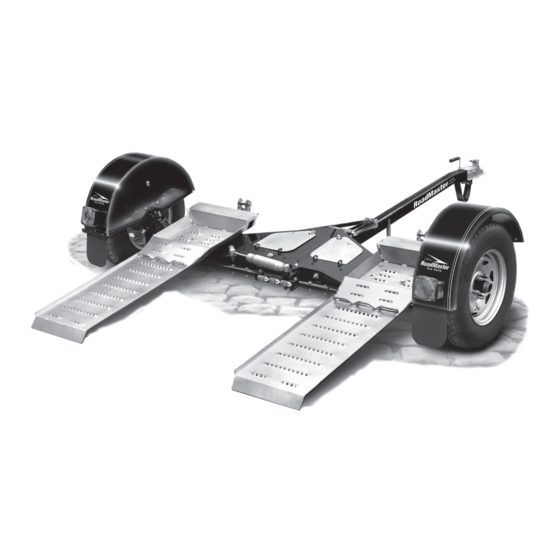
Owner's Manual
Entire contents of manual must be read by owner
This dolly will not accommodate all vehicles. The size and shape of any particular vehicle, its wheel
height and the position of fender flares, air dams or other body components may make it susceptible
to damage when it is loaded/unloaded or during transport or cornering. For these reasons, before tow-
ing any vehicle for the first time make certain it will not come into contact with the dolly.
Failure to follow these instructions may result in non-warranty damage.
It is the owner's responsibility to make certain that there is adequate clearance. ROADMASTER, Inc.
expressly disallows any claim for damage caused by inadequate clearance.
ROADMASTER, Inc. • 6110 NE 127th Ave • Vancouver, WA 98682
U.S. patent number 6,164,897
Part number 2000-1
CAUTION
Time Tested • Time Proven
800-669-9690 • fax: 360-735-9300 • roadmasterinc.com
Advertisement
Table of Contents

Related Manuals for Roadmaster 2000-1


Summary of Contents for Roadmaster 2000-1
- Page 1 Failure to follow these instructions may result in non-warranty damage. It is the owner's responsibility to make certain that there is adequate clearance. ROADMASTER, Inc. expressly disallows any claim for damage caused by inadequate clearance.
-
Page 2: Table Of Contents
WELCOME TO THE ROADMASTER FAMILY! his manual has been prepared to acquaint you with the assembly and operation of your tow dolly, and to provide you with important safety information. Read your owner’s manual cover to cover. Understand how to assemble and operate your tow dolly, and carefully follow the instructions and safety precautions. -
Page 3: Tow Dolly Safety Requirements
TOW DOLLY SAFETY REQUIREMENTS the bed tilt lock, the dolly and towed vehicle may be severely damaged. Read all instructions before assembling or op- 11. Replace broken, worn or defective tow dolly com- erating the tow dolly. Failure to understand how to ponents before towing any vehicle. -
Page 4: Before You Assemble The Dolly (Pre-Assembly Instructions)
22. Check and comply with your local, state, federal or provincial requirements for towing. 23. The RoadMaster tow dolly is not designed for com- mercial applications. Commercial use will void the war- ranty. BEFORE YOU ASSEMBLE THE DOLLY…... -
Page 5: Assembly Instructions - Wide Axle
ASSEMBLY INSTRUCTIONS — WIDE AXLE Use these instructions ONLY for wide axle assembly The wide axle setup is the most versatile, since the the axle out so the three holes in the top of the axle align with the three holes identified as W5, W6 and W7 ramps can be adjusted to accommodate either narrow or wide vehicles. -
Page 6: Narrow Axle
ASSEMBLY INSTRUCTIONS — WIDE AXLE continued from preceding page ting, the ramp can be mounted in either the narrow or wide position. It is imperative that all five of the ½" x 4½" bolts are used (on each side) to secure the axle to the To attach the ramp at the wide setting, line the ramp main bed. - Page 7 ASSEMBLY INSTRUCTIONS — NARROW AXLE 5 B Secure the ramp and axle on the other side — Re- continued from preceding page peat Steps 2B - 4B to secure the ramp and axle on the other side. It is imperative that all five of the ½" x 4½" bolts You must install the ramp, axle and tie rod on the are used (on each side) to secure the axle to the other side at the same width position as you did for the...
-
Page 8: Final Assembly
FINAL ASSEMBLY Now that the axles and ramps have been assembled, fishwire pre-installed through its length. Position the install the fenders, tires, tongue and stabilizer bars… tongue near the center of the main bed and securely connect the fishwire to the wiring harness on the main 6. - Page 9 FINAL ASSEMBLY continued from preceding page Figure 4 Figure 5 locking nut. Be sure to attach the long tab end of the stabilizer bars to the main bed and the short tab ends Bolt Torque pattern to the trailer tongue. Note that this bolt goes completely torque chart through the tongue and is used to attach both stabilizer wheel lug nuts...
-
Page 10: Before Loading The Dolly
The coupler requires a two-inch hitch ball with a and axles. 5,000 lb. capacity. 3. Check the vehicle weight — The RoadMaster tow dolly is rated to haul a maximum of 4,250 pounds. Verify that the weight of your towed vehicle and all of its contents does not exceed 4,250 pounds. -
Page 11: Using Your Tow Dolly
USING YOUR TOW DOLLY Loading being careful to keep the towed vehicle centered. As 1. Park the motorhome on a flat, level surface. Make the towed vehicle reaches the top, the ramps will au- sure that the motorhome’s engine is off, with the trans- tomatically raise. - Page 12 Note: Nearly every state requires lighting at the rear or right as necessary. of the towed vehicle. ROADMASTER manufactures Now, take the front end of the three lighting systems. See “Electrical kits,” under strap and feed at least six inches “Optional equipment and accessories,”...
-
Page 13: Towing
USING YOUR TOW DOLLY continued from preceding page The combined motorhome, dolly and towed Be certain that the bed tilt latch has been prop- vehicle will take significantly longer to accelerate erly released before backing the towed vehicle off and pass other vehicles. Stopping distances may the dolly. -
Page 14: Pulling The Dolly Empty
USING YOUR TOW DOLLY Pulling the dolly empty empty dolly. When empty, the dolly is likely to bounce around behind the motorhome. It is advisable to reduce the tire pressure by 15 psi to help alleviate bouncing and If the steering pin is not in place, the tires can vibration. -
Page 15: Alignment Instructions
ALIGNMENT INSTRUCTIONS Figure 9 Whenever the axles are changed — from narrow to wide, or from wide to narrow — the dolly must be realigned. 2. To adjust the toe-in, turn Tube A and Tube B (Figure To realign the dolly, follow the two steps below. 10) equally until Line AC (Figure 9) is between 0"... -
Page 16: Adjusting The Tiedown Straps
ADJUSTING THE TIEDOWN STRAPS ™ Even though they may appear to be identical, one TieDown strap is designed for the driver’s side and the other for the passenger’s side. Be certain that the strap is routed through the buckle, as shown in Figure 11, before towing. The Although the straps come pre-assembled, the pro- strap will not secure the towed vehicle if it is not cess is explained below (Figure 11). -
Page 17: Components
COMPONENTS 2000-1 tow dolly — rear view Item Qty. Description Part Number Item Qty. Description Part Number ... 1 ....Kingpin assembly, passenger side ..... 921009-2 ... 1 ....Lug nut ...............357310-00 includes bushings ... 1 ....Tongue assembly ..........921008 must order with axle (part number 921007-2) ... - Page 18 COMPONENTS 2000-1 tow dolly — front view Item Qty. Description Part Number ... 1 ....Tie rod assembly ........... 921005 ... 1 ....Ratchet mount with hardware......2000-31 ... 1 ....Tie down ratchet ............2110 Tie down straps (not shown) —...
-
Page 19: Limited Warranty
1a. WARRANTY OF CONFORMITY AT TIME OF SALE not provide, and will not be liable for, labor, costs of removal ROADMASTER, Inc. warrants that at the time of sale of this or reinstallation of components, disposal, shipping, freight, product it will be free from defects in material and manufacture taxes, or other incidental charges. -
Page 20: Pre-Trip Safety Checklist
All photos, illustrations and specifications contained herein are based on the latest information available at the time of publication. ROADMASTER, Inc. reserves the right to make changes at any time, without notice, in material, specifications and models, or to discontinue models. You may not use any of the contents of this document without the permission of ROADMASTER, Inc.
Need help?
Do you have a question about the 2000-1 and is the answer not in the manual?
Questions and answers