Bosch F220 Series Installation Manual
Hide thumbs
Also See for F220 Series:
- Quick manual (4 pages) ,
- Installation instructions manual (17 pages)

Related Manuals for Bosch F220 Series


Summary of Contents for Bosch F220 Series
- Page 1 F220 Series Detectors with F220-B6/C/E/R Bases Installation Manual English manual...
- Page 2 United States and/or other countries. ® Chamber Check is a registered trademark of Bosch Security Systems, Inc. in the United States. Chambermaid™ is a trademark of Bosch Security Systems, Inc. in the United States. ENVI-RO-TECH™ is a trademark of Tech Spray L.P. ® TECHSPRAY is a registered trademark of Tech Spray L.P.
-
Page 3: General Information
General Information This document covers mounting, wiring, power requirements, testing, and maintenance for the F220-B6, F220-B6C, F220-B6E, and F220-B6R Detector Bases and the F220 Series Heat and Photoelectric Smoke Detectors. Install them according to NFPA 72. NOTE! For proper system installation, read and understand NFPA-72 before installation. - Page 4 F220-B6E has a power supervision (EOL) relay NOTE! Use the F220-B6RS when a built-in sounder is needed. The F220-B6RS also has a Form A alarm relay. Refer to the F220 Series Detectors with the F220-B6RS Installation Manual (P/N: F01U029847). For addressable systems, use the F220-B6PM Addressable POPIT Master Base or F220-B6PS Addressable POPIT Base.
-
Page 5: Base Features
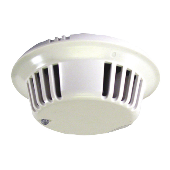
General Information | en 5 F220 Series Detectors with F220-B6/C/E/R Bases 2.1.3 Base Features Terminal 1 Remote Terminal (c) Terminal 2 Tamper Tab (Locking Bar) Terminal 3 10. Tamper Tab (Locking Bar Terminal 4 Mount) Terminal 5 11. Alignment Key (4 places) Resettable Auxiliary Power 12. - Page 6 F220 Series Detectors 2.2.1 About F220 Series Detector Heads The F220 Series Detector Heads listed inTable 2.1 each require an F220-B6 Series Base. WARNING! The F220-PTHC detects carbon monoxide (CO) as a component of a fire. Do not use the F220-PTHC as a stand-alone CO detector.
- Page 7 General Information | en 7 F220 Series Detectors with F220-B6/C/E/R Bases 2.2.2 F220 Series Detector Features Front of detector Unlocking port Light-emitting diode (LED) Back of detector Thermistor Chambermaid location (heat detectors only) Fig. 2.2 Detector Features 2.2.3 F220 Series Heat Detector Heads The F220 Heat Detector Heads can be identified by color coding (refer to Table 2.2).
-
Page 8: Technical Specifications
F220 Series Detectors with F220-B6/C/E/R Bases 2.2.4 F220 Series Smoke Detector Heads The F220 Series Smoke Detector Heads are UL Listed, open- area photoelectric smoke detectors that work with commercial fire protective signaling systems and household fire warning systems. Select the appropriate mounting base to configure the detectors for two-wire or four-wire versions (refer to Section 2.1.2 Base Comparisons on page 4). -
Page 9: Base Specifications
Operating: 8.5 VDC to 32.0 VDC RMS Ripple: 25% of DC input Table 2.5 F220 Series Detector Heads Specifications Electrical Supervision When the F220-B6 Series Bases are wired according to the instructions in this document, the control panel initiates a trouble signal when a detector is removed from its base, Bosch Security Systems, Inc. - Page 10 10 en | Install the Bases F220 Series Detectors with F220-B6/C/E/R Bases providing tamper protection. An EOL power supervision module, such as a D275 or an F220-B6E Power Supervision Base and an EOL resistor as specified by the control panel manufacturer, supervises power.
-
Page 11: Terminal Connections
Install the Bases | en 11 F220 Series Detectors with F220-B6/C/E/R Bases Wire the Bases CAUTION! When wiring bases, all terminal screws including those not wired must be tightened to prevent loose screw heads from making intermitent electrical contact with the detector head. - Page 12 12 en | Install the Bases F220 Series Detectors with F220-B6/C/E/R Bases 3.2.4 Four-wire Loop Termination One D275 End-of-Line Module (refer to Figure 3.6 on page 17) or F220-B6E Power Supervision Base (refer to Figure 3.4 on page 15) is required for each loop when using four-wire bases.
- Page 13 Install the Bases | en 13 F220 Series Detectors with F220-B6/C/E/R Bases Wire F220-B6 Two-wire Bases The F220-B6 is a 12 VDC or 24 VDC base for two-wire conventional loops. Refer to Figure 3.2 for wiring details. F220-B6 a1/a2 Initiating device circuit...
- Page 14 14 en | Install the Bases F220 Series Detectors with F220-B6/C/E/R Bases 3.5.1 F220-B6C: The F220-B6C base has a normally open alarm loop relay and auxiliary Form C (NC/C/NO) contacts. The contacts are rated for 0.5 A at 120 VAC/DC for resistive loads. Refer to Figure 3.3 for wiring details.
- Page 15 Install the Bases | en 15 F220 Series Detectors with F220-B6/C/E/R Bases unnecessary. Use only one F220-B6E per zone run. It must be the last base on the run. Refer to Figure 3.4 for wiring details. a1/a2 F220-B6E* Power input (positive [+] previous four-wire base.
- Page 16 16 en | Install the Bases F220 Series Detectors with F220-B6/C/E/R Bases 3.5.3 F220-B6R: The F220-B6R is the standard base for four-wire configurations. The Alarm Loop Relay (Terminals 1 and 2) is a normally-open relay rated for 0.5 A at 120 VAC/DC. The relay closes on alarm.
- Page 17 Install the Bases | en 17 F220 Series Detectors with F220-B6/C/E/R Bases Wire Power Supervision Modules 3.6.1 Wire F220-B6E Power Supervision Base Refer to Section 3.5.2 F220-B6E: for F220-B6E wiring instructions. 3.6.2 Wire D275 Power Supervision Module When a D275 Module (refer to Figure 3.6) is used with 12 VDC systems, connect the red wire to the output terminal (b1) on the last base in the run.
- Page 18 18 en | Install the Detector Heads F220 Series Detectors with F220-B6/C/E/R Bases Install the Detector Heads Mount the Detector Heads CAUTION! Before mounting detector heads, all terminal screws in the bases including those not wired must be tightened to prevent loose screw heads from making intermitent electrical contact with the detector head.
- Page 19 Install the Detector Heads | en 19 F220 Series Detectors with F220-B6/C/E/R Bases 4.1.2 Mounting Skirt Align the four alignment keys (refer to Figure 2.1, Item 11 on page 5 and to Figure 4.2, Item 5) and press the skirt firmly down onto the mounting base (refer to Figure 4.2, Item 3) to...
-
Page 20: Detector Head
20 en | Install the Detector Heads F220 Series Detectors with F220-B6/C/E/R Bases 4.1.3 Detector Head CAUTION! The mounting skirts and detector heads are keyed. Do not force them onto the mounting bases. Install: Install the detector head by lining up the LED on the detector head (refer to Figure 4.2, Item 6 on page 19) with the bar on the... -
Page 21: Test Mode
Install the Detector Heads | en 21 F220 Series Detectors with F220-B6/C/E/R Bases Set Detector Modes The F220 Series Smoke Detectors feature a unique magnet-operated sensitivity mode and detector test mode. 4.2.1 Test Mode Test the detector by placing the magnet next to the T mark on the mounting skirt (refer to Figure 4.2, Item 8 on page 19) for... - Page 22 22 en | Install the Detector Heads F220 Series Detectors with F220-B6/C/E/R Bases Set CleanMe Feature The Clean Me feature monitors the smoke chamber’s sensitivity and sends a trouble signal to the control panel when the sensitivity degrades to a preset level.
-
Page 23: Test The Installation
Test the Installation | en 23 F220 Series Detectors with F220-B6/C/E/R Bases NOTE! Perform the visual check before resetting power. After a reset the trouble indicators clear for 70 seconds. After 70 seconds, if the detector is in a trouble condition, trouble indications begin again. - Page 24 24 en | Test the Installation F220 Series Detectors with F220-B6/C/E/R Bases every eight seconds. This verifies the detector is receiving power and operating properly. NOTE! If a heat detector LED flashes at a rate of 4 flashes/sec, the detector is either cold (below +32°F [0°C]), out of sensitivity range, or defective.
- Page 25 Test the Installation | en 25 F220 Series Detectors with F220-B6/C/E/R Bases Test the Alarm Loop Checkthe voltage across the EOL resistor of each alarm loop to verify wiring losses do not exceed control panel manufacturer’s specifications. Test CO Sensors Removing the detector head or resetting the detector’s power...
- Page 26 26 en | Test the Installation F220 Series Detectors with F220-B6/C/E/R Bases 4998138694 -04 | 2007.01 Installation Manual Bosch Security Systems, Inc.
- Page 27 Test the Installation | en 27 F220 Series Detectors with F220-B6/C/E/R Bases Bosch Security Systems, Inc. Installation Manual 4998138694 -04 | 2007.01...
- Page 28 Bosch Security Systems, Inc. 130 Perinton Parkway Fairport, NY 14450-9199 Customer Service: (800) 289-0096 Technical Support: (888) 886-6189 www.boschsecurity.us © Bosch Security Systems, Inc., 2007...
Need help?
Do you have a question about the F220 Series and is the answer not in the manual?
Questions and answers