Advertisement
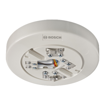
Conventional Detectors and Bases
MODEL
FCA-350-B4
FCA-350-B6
4 Wire 24V Base
FCA-350-B6R24
4 Wire 12V Base
FCA-350-B6R12
NOTES:
Alarm current for 2-wire operation applies to the FACP Initiating Device Circuit and detector.
Alarm current for 4-wire operation applies to the Auxilliary Power Supply and detector.
FCA-350-B4 and FCA-350-B6 must be current limited by the FACP
Refer to the Technical Bulletin for the following UL listed compatible detectors. Connect these detectors only to a listed-
compatible control panel. Refer to the control panel installation manual for additional instructions. Smoke detectors are
not to be used with detector guards unless the combination has been evaluated and found suitable for that purpose:
FCP-350-P Multi-criteria Smoke Detector (Compatibility ID HD-3)
FCP-350-PTH Multi-criteria Smoke and Heat Detector (Compatibility ID HD-3)
FCH-350-135/FCH-350-190 Fixed Temperature and Rate of Rise Detector (Compatibility ID HD-3)
Detectors must be installed and maintained in accordance with applicable NFPA standards, local codes and any authority
having jurisdiction. Refer to NFPA 72 "National Fire Alarm and Signaling Code" for installation guidelines and testing
procedures. Smoke detectors should be tested in accordance with NFPA 72, section on "Inspection, Testing and
Maintenance".
Seal conduit openings in the electrical box with 3M Weatherban #606 nonflammable sealing compound (or equivalent)
to reduce the stack effect. Attach the detector to the base by turning the detector clockwise until it stops.
Bosch Security Systems, B.V.
Torenallee 49
5617 BA Eindhoven,
Netherlands
INSTALLATION AND MAINTENANCE INSTRUCTIONS
BASE SPECIFICATIONS
Base
Compatible
ID
Detector ID
HB-55
HD-3 or HD-5
HB-55
HD-3 or HD-5
N/A
HD-3 or HD-5
N/A
HD-3 or HD-5
Alarm Current
limit externally
150mA
@12.0 - 33.0V max
limit externally
150mA
@12.0 - 33.0V max
43mA (58mA @ 30.0V max)
47mA (75mA @ 18.0V max)
Mounting Box
3" Octagonal
4" Octagonal / 4" Square
4" Octagonal / 4" Square
4" Octagonal / 4" Square
DWG # HA-06-446, Rev 05/22
PAGE 1 of 2
PART # 1700-12680
Advertisement
Table of Contents

Related Manuals for Bosch FCA-350-B4


Summary of Contents for Bosch FCA-350-B4
- Page 1 Alarm current for 4-wire operation applies to the Auxilliary Power Supply and detector. FCA-350-B4 and FCA-350-B6 must be current limited by the FACP Refer to the Technical Bulletin for the following UL listed compatible detectors. Connect these detectors only to a listed- compatible control panel.
- Page 2 3 seconds and never alarm or latch red. 3. Upon reset, the smoke detector LED should blink Green every 3 seconds. If the detector blinks red, it should be replaced. FCP-350-P/FCP-350-PTH Bosch Security Systems, B.V. DWG # HA-06-446, Rev 05/22 Torenallee 49 PAGE 2 of 2...
Need help?
Do you have a question about the FCA-350-B4 and is the answer not in the manual?
Questions and answers