
Related Manuals for Bosch 520 Series


Summary of Contents for Bosch 520 Series
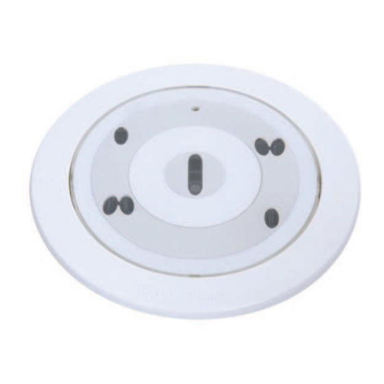
- Page 1 Automatic Detectors LSN improved FAP‑O 520 | FAP‑O 520‑P | FAP‑OC 520 | FAP‑OC 520‑P Operation Guide...
-
Page 3: Table Of Contents
Technical Data Detector and Trim Ring Detector Base Mounting Boxes Remote indicator Appendix Abbreviations Order Overview 7.2.1 Detector and Trim Ring 7.2.2 Detector Bases/Remote indicators 7.2.3 Mounting Boxes 7.2.4 Service tools/accessories Bosch Sicherheitssysteme GmbH Operation Guide 2019.11 | 4.0 | F.01U.025.877... -
Page 4: Product Description
The FAP‑520 Detectors can be connected directly to the Local SecurityNetwork LSN. Accessories The 520 Series Detectors are generally mounted flush with the ceiling in false ceilings. The detector and base are installed in a robust ceiling mount back box. In addition, a housing for mounting within concrete ceilings can be used. - Page 5 For the detector test and detector exchange, a special user-friendly service accessory is available. Overview of the 520 Series Detectors and Accessories FAA-500-TR-W FAP-O 520 FAP-OC 520...
-
Page 6: Performance Features
Service Accessories: - FAA-500-RTL Detector Exchanger for 500 and 520 Series Detectors - FAA-500-TTL Test Adapter with Magnet for 500 and 520 Series Detectors Performance Features – Fulfills the highest aesthetic demands through the flush-mounting design and the possibility of color toning –... -
Page 7: System Description
Automatic Detectors LSN improved Product Description | en System Description All detectors in the 520 Series are equipped with two optical sensors and a pollution sensor. The FAP‑OC 520 Multisensor Detector contains a gas sensor as an additional detection channel. The response sensitivity of the detector can be programmed with the programming software via the LSN network. -
Page 8: Led Operation
In case of an alarm, the LED flashes red. The detector is set back to standby if the alarm is reset via the fire panel and if the cause of the alarm is gone. LED Operation Status Standby Alarm red, flashes Trouble Test mode green, flashes once every second 2019.11 | 4.0 | F.01U.025.877 Operation Guide Bosch Sicherheitssysteme GmbH... -
Page 9: Planning Notes
General Notes Notice! The 520 Series Detectors are approved for indoor use only! The detectors must be installed exclusively in the FAA‑500 Series Bases provided. In addition, the detector base must be installed in an FAA‑500‑BB Ceiling Mount Back Box or in an FAA‑500‑SB-H Surface Mount Back Box. - Page 10 When configuring the detectors, it is essential to ensure that no mesh structures are created. FPA-5000 FPA-5000 Mesh structures within a Mesh structures within a stub structure loop structure Tab. 2.2: Unusable network structures 2019.11 | 4.0 | F.01U.025.877 Operation Guide Bosch Sicherheitssysteme GmbH...
-
Page 11: Installation
Automatic Detectors LSN improved Installation | en Installation Notice! The 520 Series Detectors may only be installed with an FAA‑500 Detector Base in combination with an FAA‑500‑BB Ceiling Mount Back Box or an FAA‑500‑SB-H Surface Mount Back Box. Notice! By default, the bases are equipped with a spring for mounting the detector in concrete and wooden ceilings. -
Page 12: Detector Base/Detector Base With Relay
Detector bases with relay (FAA‑500‑R) can only be used in combination with the modular fire panel series 1200 and 5000. In cases where relay bases are used, no external detector alarm display can be connected. 2019.11 | 4.0 | F.01U.025.877 Operation Guide Bosch Sicherheitssysteme GmbH... - Page 13 Mount for cable ties Fastening slot FAA-500(-R) LSN a1/a2 LSN b1 Figure 3.6: Connection of bases Position Description Position Description Fire panel Next detector Remote indicator (optional), not for relay bases Bosch Sicherheitssysteme GmbH Operation Guide 2019.11 | 4.0 | F.01U.025.877...
- Page 14 Turn the base until the fastening screws are approximately in the middle of the long slots (3). Adjust the bases around this position until they appear in a line. Tighten the four screws. 2019.11 | 4.0 | F.01U.025.877 Operation Guide Bosch Sicherheitssysteme GmbH...
-
Page 15: Address Allocation
The packaging of the detectors with C sensor consists of tear-resistant PE‑ALU laminated film and must be cut open carefully. Do not remove the protective film until the detector is ready to be fitted. Bosch Sicherheitssysteme GmbH Operation Guide 2019.11 | 4.0 | F.01U.025.877... - Page 16 To remove, push the detector gently upwards in the middle. In this way the locking is released. To take off the trim ring, carefully lift it up on one side. 2019.11 | 4.0 | F.01U.025.877 Operation Guide Bosch Sicherheitssysteme GmbH...
-
Page 17: Built-In Housing For Concrete Ceilings
The FAA-500-SB-H Surface Mount Back Box allows flush and surface cable duct. The box has a seal for damp rooms. For surface cable duct use the side knockouts. For flush cable duct, there are two openings in the bottom. Bosch Sicherheitssysteme GmbH Operation Guide 2019.11 | 4.0 | F.01U.025.877... -
Page 18: Remote Indicator
Ensure, that the maximum current consumption of 20 mA is not exceeded b) Use point‑type automatic Bosch detectors, which have an internal resistor that limits the current consumption. Before assembly remove the cap from the base plate Unlock the snap‑fit hook by pressing on it with a flat object and lift the cap carefully... - Page 19 Secure the cable with a zip tie on the base plate. FAA‑420‑RI‑DIN Warning! Malfunction and Damage Note the maximum permitted current supply respectively the input voltage range of the functional modes. Wire the remote indicator as shown. Bosch Sicherheitssysteme GmbH Operation Guide 2019.11 | 4.0 | F.01U.025.877...
- Page 20 Place the cap on the base plate in such a way that the two hooks are inserted into the slits. Press the cap lightly onto the base plate until the snap‑fit‑hook engages. 2019.11 | 4.0 | F.01U.025.877 Operation Guide Bosch Sicherheitssysteme GmbH...
-
Page 21: Programming
Sensitivity O unit detector (FAP‑O 520) selectable via the programming software Office (smokers) / waiting room / restaurant / conference room Conference room / waiting room / exhibition hall Warehouse with vehicle traffic Bosch Sicherheitssysteme GmbH Operation Guide 2019.11 | 4.0 | F.01U.025.877... - Page 22 This can be carried out via the fire panel or via the reed switch at the detector with the help of a magnet (see Maintenance and Service, page 23). 2019.11 | 4.0 | F.01U.025.877 Operation Guide Bosch Sicherheitssysteme GmbH...
-
Page 23: Maintenance And Service
DIN VDE 0833 strictly apply in Germany; these refer to the maintenance intervals specified by the manufacturer. Notice! The 520 Series Detectors do not require to be removed from their bases for routine maintenance. If occasionally a detector requires replacement due to a design change or damage to the device then this should be carried out by a qualified engineer. -
Page 24: Notes For The Service
– Detector test device for optical fire detector and – FAA‑500‑TTL test adapter with magnet For the OC detector you need in addition a CO testing gas for detector with CO sensor. 2019.11 | 4.0 | F.01U.025.877 Operation Guide Bosch Sicherheitssysteme GmbH... -
Page 25: Inspection Procedure For Fap-Oc 520
Now hold the test device under the detector so that the test beaker is flush with the trim ring and seal it tightly. Bosch Sicherheitssysteme GmbH Operation Guide 2019.11 | 4.0 | F.01U.025.877... -
Page 26: Inspection Procedure For Fap-O 520
The detector will now remain in test readiness for 60 sec with automatically set test parameters (e.g. reduction of the delay time to 15 sec). The green LED flashes for as long as the detector remains in test readiness. 2019.11 | 4.0 | F.01U.025.877 Operation Guide Bosch Sicherheitssysteme GmbH... -
Page 27: Repair
Packaging Film of the Fire Detectors with C sensor: The packaging bag of the multisensor detectors with C sensor consists of tear‑resistant PE‑ALU laminated film and may be disposed of with the household garbage. Bosch Sicherheitssysteme GmbH Operation Guide 2019.11 | 4.0 | F.01U.025.877... -
Page 28: Technical Data
Protection class as per IP 33 IP 53 IEC 60529 Dimensions: – Detector without trim Ø 113 mm x 55 mm (without base)/Ø 113 x 70 mm (with base) ring – Detector with trim Ø 150 mm x 55 mm (without base)/Ø 150 x 70 mm (with base) ring 2019.11 | 4.0 | F.01U.025.877 Operation Guide Bosch Sicherheitssysteme GmbH... -
Page 29: Detector Base
FAA‑500‑BB Ceiling Mount Back Box Mounting dimensions: – Thickness of the false ceiling Max. 32 mm – Required bored hole Ø 130 mm (tolerance -1 mm to +5 mm) – Installation height 11 cm Max. cable diameter 1.4 cm Bosch Sicherheitssysteme GmbH Operation Guide 2019.11 | 4.0 | F.01U.025.877... -
Page 30: Remote Indicator
– Operating mode 2: 11 to 14 mA – Operating mode 3 : 3 mA Permissible wire gauge 0,4 - 1,3 mm 0,6 - 1,0 mm Display medium 1 LED 2 LED Dimensions 85 x 85 x 28 mm 85 x 85 x 35 mm Weight 45 g 65 g 2019.11 | 4.0 | F.01U.025.877 Operation Guide Bosch Sicherheitssysteme GmbH... -
Page 31: Appendix
VdS Schadenverhütung GmbH (company name) Order Overview 7.2.1 Detector and Trim Ring Description Product ID FAP-O 520 Optical Fire Detector LSN improved, white F.01U.510.149 FAP-OC 520 Multisensor Fire Detector LSN improved, optical/chemical, F.01U.510.151 white Bosch Sicherheitssysteme GmbH Operation Guide 2019.11 | 4.0 | F.01U.025.877... -
Page 32: Detector Bases/Remote Indicators
Product ID FAA-500 LSN Detector Base 4.998.151.297 FAA-500-R LSN Detector Base with relay (for connection to 4.998.151.299 FPA‑5000 only) FAA-420-RI-DIN Remote indicator for DIN application F.01U.289.620 FAA-420-RI-ROW Remote indicator F.01U.289.120 2019.11 | 4.0 | F.01U.025.877 Operation Guide Bosch Sicherheitssysteme GmbH... -
Page 33: Mounting Boxes
FAA-500-RTL Detector Exchanger for 500 and F.01U.508.720 520 Series Detectors FAA-500-TTL Test Adapter with Magnet for F.01U.508.725 500 and 520 Series Detectors Test Device for Optical Fire Detectors 4.998.112.071 Test gas for smoke detector + CO sensor F.01U.301.469 for multisensor detectors with C-sensor, DU = 12 pieces. - Page 34 | Appendix Automatic Detectors LSN improved 2019.11 | 4.0 | F.01U.025.877 Operation Guide Bosch Sicherheitssysteme GmbH...
- Page 36 Bosch Sicherheitssysteme GmbH Robert-Bosch-Ring 5 85630 Grasbrunn Germany www.boschsecurity.com © Bosch Sicherheitssysteme GmbH, 2019...
Need help?
Do you have a question about the 520 Series and is the answer not in the manual?
Questions and answers