Bosch FCP‑320 Series User Manual

Bosch FCP‑320 Series User Manual

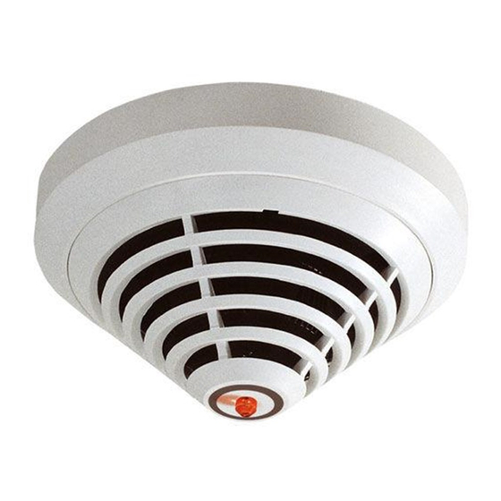
Conventional automatic fire detector
Hide thumbs Also See for FCP‑320 Series:

Advertisement

Conventional Automatic Fire Detectors
FCP‑320/FCH‑320
en
User manual

Advertisement

Table of Contents
loading

Summary of Contents for Bosch FCP‑320 Series

  • Page 1 Conventional Automatic Fire Detectors FCP‑320/FCH‑320 User manual...
  • Page 3: Table Of Contents

    Detector Base Sounders Remote Indicators Service Accessories Maintenance and Service Coding of the Detector Types Test Procedure for Detectors with C-Sensor Test Procedure for Detectors without C-Sensor Warranty Repair Disposal Additional Documentation Bosch Sicherheitssysteme GmbH 2021.03 | 11 | F.01U.004.377 User manual...
  • Page 4 | Table of contents Conventional Automatic Fire Detectors Specifications Abbreviations 2021.03 | 11 | F.01U.004.377 Bosch Sicherheitssysteme GmbH User manual...
  • Page 5: Product Description

    The 320 Series detectors are available with either a 470 Ω alarm resistor or a 820 Ω alarm resistor. The operating voltage range is 8.5 V DC to 30 V DC, which allows the detectors to be used with almost every common conventional fire panel. Bosch Sicherheitssysteme GmbH 2021.03 | 11 | F.01U.004.377 User manual...
  • Page 6: System Overview

    System Description Up to two detection principles are integrated into the FCP-320/FCH-320 Series Fire Detectors: – Optical (for smoke): O – Thermal (for heat): T – Chemical (for gas): C 2021.03 | 11 | F.01U.004.377 Bosch Sicherheitssysteme GmbH User manual...
  • Page 7: Features

    (not required for the FCH‑T 320/ FCH‑T 320‑R470/FCH‑T 320‑FSA Heat Detectors). – Connectable to Bosch fire panels and the majority of conventional fire panels available on the market. – Two variants with 820 Ω alarm resistor and 470 Ω alarm resistor enables the detector application with nearly all conventional fire panels.
  • Page 8: Planning

    DIBt (Deutsches Institut für Bautechnik/German Institute for Building Technology). When planning for fire barriers conforming to DIBt, the FCH-T 320‑FSA detector has already been set to class A1R. Both models have DIBt approval. 2021.03 | 11 | F.01U.004.377 Bosch Sicherheitssysteme GmbH User manual...
  • Page 9: Installation

    The MS 400 Detector Base is the standard detecor base. It has seven screw terminals. MS 400 B The standard MS 400 Detector Base with Bosch-branding. FAA-420-SEAL Seal for using the MS 400 and MS 400 B detectors in a humid environment. The TPE seal protects the detector reliably against the penetration of condensed water.
  • Page 10: Overview Of Detector Base Sounder

    Cable feed and outfeed can be on the same side. For cable feed at the FAA-420-SEAL and MSC 420 puncture the sealing with a pointed tool. Do not cut the sealing with a knife. 2021.03 | 11 | F.01U.004.377 Bosch Sicherheitssysteme GmbH User manual...
  • Page 11: Wiring

    Conventional Automatic Fire Detectors Installation | en Ø 120 Ø 100 Wiring Notice! Keep screening wire as short as possible and insulate it. Bosch Sicherheitssysteme GmbH 2021.03 | 11 | F.01U.004.377 User manual...
  • Page 12: Wiring Ms 400/Ms 400 B

    Terminals for looping through the power supply to subsequent elements FAA-420-RI Remote Indicator Notice! When using unshielded cables for the connection of the remote indicator, the maximum cable length is 3m. No limitation when using shielded cables. 2021.03 | 11 | F.01U.004.377 Bosch Sicherheitssysteme GmbH User manual...
  • Page 13: Wiring Msr 320

    | a2 – yellow, connects to b1/b2 V+ white, connects to a1/a2 V- green, connects to shielding wire NC / C / NO Changeover relay (for the MSR 320 only) Bosch Sicherheitssysteme GmbH 2021.03 | 11 | F.01U.004.377 User manual...
  • Page 14: Wiring Mss 300

    The detector head can be locked into the base (removal protection). The locking feature is activated by breaking the bolt (X) out of the base and pushing it into the corresponding guide, as shown in , page 14 . 2021.03 | 11 | F.01U.004.377 Bosch Sicherheitssysteme GmbH User manual...
  • Page 15: Detector Removal

    Locked detector heads are disassembled by inserting a screwdriver into the unlocking opening (Y) so that the bolt is pushed upward; at the same time, the detector head should be turned to the left. Figure 4.2: Detector Removal (Locked Detector) Bosch Sicherheitssysteme GmbH 2021.03 | 11 | F.01U.004.377 User manual...
  • Page 16: Accessories

    If the detector is mounted in a sports facility, for example, the protective basket prevents balls or other sports equipment from hitting the detector and damaging it. 2021.03 | 11 | F.01U.004.377 Bosch Sicherheitssysteme GmbH User manual...
  • Page 17: Ssk 400 Protective Dust Cover

    For connection to the standard bases MS400/MS400B note the following: Notice! When using unshielded cables for the connection of the remote indicator, the maximum cable length is 3m. No limitation when using shielded cables. Bosch Sicherheitssysteme GmbH 2021.03 | 11 | F.01U.004.377 User manual...
  • Page 18 Note the maximum permitted current supply respectively the input voltage range of the functional modes. Wire the remote indicator as shown. Mode Terminal connection Alarm condition The remote indicator shows steady red light. The remote indicator shows steady red light. 2021.03 | 11 | F.01U.004.377 Bosch Sicherheitssysteme GmbH User manual...
  • Page 19 Ensure, that the maximum current feed of 30 mA is not exceeded b) Use point‑type automatic Bosch detectors, which have an internal resistor that limits the current consumption. Before assembly remove the cap from the base plate Unlock the snap‑fit hook by pressing on it with a flat object and lift the cap carefully...
  • Page 20 Secure the cable with a zip tie on the base plate. Technical specifications FAA‑420‑RI‑ROW FAA‑420‑RI‑DIN Operating Voltage depends on current feed – Operating mode 1: depends on current feed – Operating mode 2: 8,5 to 33 V DC 2021.03 | 11 | F.01U.004.377 Bosch Sicherheitssysteme GmbH User manual...
  • Page 21 – Operating mode 2: 11 to 14 mA – Operating mode 3: 3 mA Permissible wire gauge 0,4 - 1,3 mm 0,6 - 1,0 mm Display medium 1 LED 2 LED Dimensions 85 x 85 x 28 mm 85 x 85 x 35 mm Weight 45 g 65 g Bosch Sicherheitssysteme GmbH 2021.03 | 11 | F.01U.004.377 User manual...
  • Page 22: Order Overview

    Standard Detector Base for surface-mounted and 4.998.021.535 flush-mounted cable feed MS 400 B Standard Detector Base for surface-mounted and F.01U.215.139 flush-mounted cable feed, with Bosch-branding FAA-420-SEAL Damp Room Seal for the MS 400 and MS 400 B F.01U.215.142 Detector bases (1 pack = 10 pieces) MSR 320 Conventional Detector Base with Relay for surface- 4.998.114.565...
  • Page 23: Installation Accessories

    Ordering only per 12 pieces FME-TEST-CO Solo CO Testing Gas (250 ml) F.01U.301.469 SOLO461 Heat Detector Test Kit F.01U.363.162 SOLO770 Spare battery baton F.01U.363.163 FME-TESTIFIRE Multi-Stimulus Testing Tool F.01U.143.407 FME-TS3 Smoke Capsule F.01U.143.404 Bosch Sicherheitssysteme GmbH 2021.03 | 11 | F.01U.004.377 User manual...
  • Page 24 | Order Overview Conventional Automatic Fire Detectors Type Number Designation Product ID SOLO100 Telescopic Access Pole 4.998.112.069 SOLO101 Fixed Extension Pole 4.998.112.070 SOLO610 Test Equipment Bag 4.998.112.073 2021.03 | 11 | F.01U.004.377 Bosch Sicherheitssysteme GmbH User manual...
  • Page 25: Maintenance And Service

    DIN VDE 0833; these regulations stipulate reference to the manufacturer's instructions for maintenance intervals. – Maintenance and inspection work should be carried out regularly and by trained personnel. – BOSCH ST recommends a functional and visual inspection at least once a year. Testing Detector Type FCP-O320 FCH-T320 FCP-OT320...
  • Page 26: Coding Of The Detector Types

    30 to 35 ppm is required when the chemical sensor is tested. This is guaranteed if the test is performed with the CO Test Gas bottle as described. 2021.03 | 11 | F.01U.004.377 Bosch Sicherheitssysteme GmbH User manual...
  • Page 27: Test Procedure For Detectors Without C-Sensor

    Defective detectors are exchanged and should be disposed of in accordance with statutory regulations. Additional Documentation Notice! Refer to the technical documentation for this product available for download at www.boschsecurity.com. Bosch Sicherheitssysteme GmbH 2021.03 | 11 | F.01U.004.377 User manual...
  • Page 28 120 x 63,5 mm Housing material / color ABS / white, similar to RAL 9010, matte surface Weight without packaging approx. 80 g approx. 75 g Weight with packaging approx. 125 g approx. 115 g 2021.03 | 11 | F.01U.004.377 Bosch Sicherheitssysteme GmbH User manual...
  • Page 29 99,5 x 52 mm Dimensions with base circumference 120 x 63,5 mm Housing material / color ABS / white, similar to RAL 9010, matte surface Weight without packaging approx. 75 g Weight with packaging approx. 115 g Bosch Sicherheitssysteme GmbH 2021.03 | 11 | F.01U.004.377 User manual...
  • Page 30 2 min 5 min 30 s 30 s 2 min 20 s 1 min 3 min 13 s 20 s 1 min 40 s 40 s 2 min 25 s 2021.03 | 11 | F.01U.004.377 Bosch Sicherheitssysteme GmbH User manual...
  • Page 31 Light Emitting Diode Local SecurityNetwork Polypropylene Universelle Gefahrenmeldezentrale (Universal Security System) Verband Deutscher Elektrotechniker e.V. (German Association for Electrical, Electronic & Information Technologies) VdS Schadenverhütung GmbH Optical/Chemical Optical/Thermal Optical Thermal Bosch Sicherheitssysteme GmbH 2021.03 | 11 | F.01U.004.377 User manual...
  • Page 32 | Abbreviations Conventional Automatic Fire Detectors 2021.03 | 11 | F.01U.004.377 Bosch Sicherheitssysteme GmbH User manual...
  • Page 34 Bosch Sicherheitssysteme GmbH Robert-Bosch-Ring 5 85630 Grasbrunn Germany www.boschsecurity.com © Bosch Sicherheitssysteme GmbH, 2021 202103101704...

Table of Contents