
Related Manuals for Bosch FCP‑O 500


Summary of Contents for Bosch FCP‑O 500
- Page 1 Conventional Automatic Detectors FCP‑O 500 | FCP‑OC 500 | FCP‑O 500‑P | FCP‑OC 500‑P Operation Guide...
-
Page 3: Table Of Contents
Detector and Trim Ring Detector Base Mounting Boxes Remote indicator Appendix Abbreviations Order Overview 6.2.1 Detector and Trim Ring 6.2.2 Detector bases / Remote indicators 6.2.3 Mounting Boxes 6.2.4 Service tools/accessories Bosch Sicherheitssysteme GmbH Operation Guide 2019.11 | 5.0 | F.01U.003.962... -
Page 4: Product Description
The FCP‑500 series are conventional technology detectors. Due to their current consumption, a four-wire connection is required. Thus, they can be operated with numerous different fire panels. 2019.11 | 5.0 | F.01U.003.962 Operation Guide Bosch Sicherheitssysteme GmbH... - Page 5 White Trim Ring for detectors 500 and 520 Series - FAA-500-TR-P Transparent Trim Ring with color toning inserts for detectors 500 and 520 Series Conventional Detector Bases: - FCA-500-EU Conventional Detector Base Bosch Sicherheitssysteme GmbH Operation Guide 2019.11 | 5.0 | F.01U.003.962...
-
Page 6: Performance Features
The alarm will only be triggered automatically if the signal combination corresponds with the detector’s programmed characteristic diagram. Consequently, an extremely high tolerance to unwanted alarms is achieved. 2019.11 | 5.0 | F.01U.003.962 Operation Guide Bosch Sicherheitssysteme GmbH... -
Page 7: Configuration Of The Detector
Moreover, plausibility checking of the various signals makes it possible to detect errors in the evaluation electronics and the LEDs. Bosch Sicherheitssysteme GmbH Operation Guide 2019.11 | 5.0 | F.01U.003.962... -
Page 8: Led Operation
In test mode, the contamination level can be read via the number of the red LED flashes (refer to Reading the Contamination Level, page 23). 2019.11 | 5.0 | F.01U.003.962 Operation Guide Bosch Sicherheitssysteme GmbH... -
Page 9: Planning Notes
– A minimum distance of 50 cm from lamps must be maintained. The detectors may not be mounted in a cone of light from lamps. – Maximum permitted air speed: 20 m/s. Bosch Sicherheitssysteme GmbH Operation Guide 2019.11 | 5.0 | F.01U.003.962... -
Page 10: Installation
Wittmann-Komet, Metal Cutting Saws GmbH & Co. KG, Alte Str. 28, D-79576 Weil am Rhein, Tel. ++49‑7621‑9783-0, www.wittmann-komet.de 129 m m Figure 3.2: Plan view and side view of the ceiling mount back box FAA‑500‑BB 2019.11 | 5.0 | F.01U.003.962 Operation Guide Bosch Sicherheitssysteme GmbH... -
Page 11: Detector Base/Detector Base With Eol Resistor
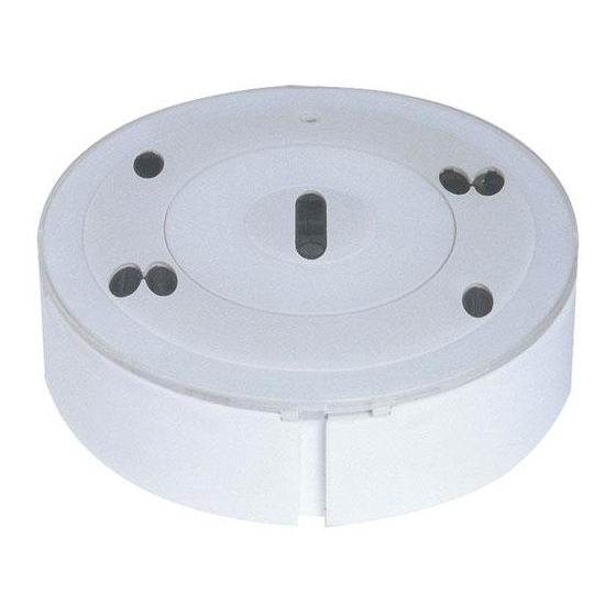
As the last base on the stub line you always have to place an FCA‑500‑E‑EU detector base. Inside the base, a suitable EOL resistor has to be mounted between the two screw clamps (refer to figure, position EOL). Bosch Sicherheitssysteme GmbH Operation Guide 2019.11 | 5.0 | F.01U.003.962... - Page 12 By breaking off the printed circuit board tongue, the alarm contact resistance is changed from 0 Ω to 680 Ω (refer to figure). Notice! For all Bosch fire panels, the alarm contact resistance has to be changed to 680 Ω. 0 W --> 680 W Figure 3.5: EOL resistor/alarm contact resistance Connecting the base Wire up the LSN base according to the labeling in the inner ring (3).
- Page 13 With a six‑wire connection (refer to table), all following detectors of a stub will continue to operate even in case of a fault. FCA-500-EU FCA-500-EU FCA-500-E-EU a1/a2 b1/b2 Figure 3.7: Connection of the detector base with 4 wires Position Description Remote indicator (optional) Bosch Sicherheitssysteme GmbH Operation Guide 2019.11 | 5.0 | F.01U.003.962...
- Page 14 Turn the base until the fastening screws are approximately in the middle of the long slots (3). Adjust the bases around this position until they appear in a line. Tighten the four screws. 2019.11 | 5.0 | F.01U.003.962 Operation Guide Bosch Sicherheitssysteme GmbH...
-
Page 15: Detector And Trim Ring
(9). Removing the detector and trim ring To remove, push the detector gently upwards in the middle. In this way the locking is released. Bosch Sicherheitssysteme GmbH Operation Guide 2019.11 | 5.0 | F.01U.003.962... -
Page 16: Built-In Housing For Concrete Ceilings
20 mm 14,5 mm Figure 3.12: FAA-500-SB-H Surface Mount Back Box The FAA-500-SB-H Surface Mount Back Box allows flush and surface cable duct. The box has a seal for damp rooms. 2019.11 | 5.0 | F.01U.003.962 Operation Guide Bosch Sicherheitssysteme GmbH... -
Page 17: Remote Indicators
Ensure, that the maximum current consumption of 20 mA is not exceeded b) Use point‑type automatic Bosch detectors, which have an internal resistor that limits the current consumption. Before assembly remove the cap from the base plate Unlock the snap‑fit hook by pressing on it with a flat object and lift the cap carefully... - Page 18 Secure the cable with a zip tie on the base plate. Notice! When using unshielded cables for the connection of the remote indicator, the maximum cable length is 3m. No limitation when using shielded cables. FAA‑420‑RI‑DIN 2019.11 | 5.0 | F.01U.003.962 Operation Guide Bosch Sicherheitssysteme GmbH...
- Page 19 Place the cap on the base plate in such a way that the two hooks are inserted into the slits. Press the cap lightly onto the base plate until the snap‑fit‑hook engages. FAA‑420‑RI‑ROW Wire the remote indicator as shown. Bosch Sicherheitssysteme GmbH Operation Guide 2019.11 | 5.0 | F.01U.003.962...
- Page 20 Place the cap on the base plate in such a way that the two hooks are inserted into the slits. Press the cap lightly onto the base plate until the snap‑fit‑hook engages. 2019.11 | 5.0 | F.01U.003.962 Operation Guide Bosch Sicherheitssysteme GmbH...
-
Page 21: Maintenance And Service
– Maintenance and inspection work should be carried out regularly and by trained technical personnel. – Bosch Sicherheitssysteme GmbH recommends a functional and visual inspection at least once a year. Test steps Detector type Check of the LED display... -
Page 22: General Notes For Detector Testing
If you imagine the CO sensor (Pos. CO) to be in a 12 o’clock position, the reed switch (Pos. R) is located at approximately 2 o’clock. Figure 4.1: Position of reed switch Bring the magnet close to the reed switch. 2019.11 | 5.0 | F.01U.003.962 Operation Guide Bosch Sicherheitssysteme GmbH... -
Page 23: Inspection Procedure For Fcp-O 500
Activate the reed switch with the magnet of the test tool. The LED of the detector flashes green once a second as soon as the reed switch has been triggered. Bosch Sicherheitssysteme GmbH Operation Guide 2019.11 | 5.0 | F.01U.003.962... -
Page 24: Electronic Function Test (Optional)
Packaging Film of the Fire Detectors with C sensor: The packaging bag of the multisensor detectors with C sensor consists of tear‑resistant PE‑ALU laminated film and may be disposed of with the household garbage. 2019.11 | 5.0 | F.01U.003.962 Operation Guide Bosch Sicherheitssysteme GmbH... -
Page 25: Technical Data
-10 °C to +50 °C -20 °C to +65 °C temperature Permitted relative <95 % (non‑condensing) humidity Protection class as per IP 33 IP 53 IEC 60529 Dimensions: – Detector without trim Ø 113 mm x 55 mm (without base)/Ø 113 x 70 mm (with base) ring Bosch Sicherheitssysteme GmbH Operation Guide 2019.11 | 5.0 | F.01U.003.962... -
Page 26: Detector Base
Polycarbonate, signal white (RAL 9003) Dimensions (Ø x H) 145.6 x 63.5 mm Weight (without/with pack.) Approx. 200 g/280 g Approx. 210 g/290 g Mounting Boxes FAA‑500‑BB Ceiling Mount Back Box Mounting dimensions: – Thickness of the false ceiling Max. 32 mm 2019.11 | 5.0 | F.01U.003.962 Operation Guide Bosch Sicherheitssysteme GmbH... -
Page 27: Remote Indicator
Current feed 3 to 30 mA – Operating mode 1: 3 to 30 mA – Operating mode 2: 11 to 14 mA – Operating mode 3: 3 mA Permissible wire gauge 0,4 - 1,3 mm 0,6 - 1,0 mm Bosch Sicherheitssysteme GmbH Operation Guide 2019.11 | 5.0 | F.01U.003.962... - Page 28 | Technical Data Conventional Automatic Detectors FAA‑420‑RI‑ROW FAA‑420‑RI‑DIN Display medium 1 LED 2 LED Dimensions 85 x 85 x 28 mm 85 x 85 x 35 mm Weight 45 g 65 g 2019.11 | 5.0 | F.01U.003.962 Operation Guide Bosch Sicherheitssysteme GmbH...
-
Page 29: Appendix
VdS Schadenverhütung GmbH (company name) Order Overview 6.2.1 Detector and Trim Ring Description Product ID FCP-O 500 Conventional Optical Fire Detector, white F.01U.510.649 FCP-OC 500 Conventional Multisensor Fire Detector, optical/chemical, F.01U.510.653 white Bosch Sicherheitssysteme GmbH Operation Guide 2019.11 | 5.0 | F.01U.003.962... -
Page 30: Detector Bases / Remote Indicators
Detector bases / Remote indicators Description Product ID FCA-500-EU Conventional Detector Base 4.998.510.647 FCA-500-E-EU Conventional Detector Base with EOL resistor 4.998.510.648 FAA-420-RI-DIN Remote indicator for DIN application F.01U.289.620 FAA-420-RI-ROW Remote indicator F.01U.289.120 2019.11 | 5.0 | F.01U.003.962 Operation Guide Bosch Sicherheitssysteme GmbH... -
Page 31: Mounting Boxes
3 extension poles Extension Pole made of fiberglass (1 m) 4.998.112.070 Transport Bag for test devices and 4.998.112.073 accessories * DU = delivery unit, PE = pieces, PU = packaging unit Bosch Sicherheitssysteme GmbH Operation Guide 2019.11 | 5.0 | F.01U.003.962... - Page 32 | Appendix Conventional Automatic Detectors 2019.11 | 5.0 | F.01U.003.962 Operation Guide Bosch Sicherheitssysteme GmbH...
- Page 34 Bosch Sicherheitssysteme GmbH Robert-Bosch-Ring 5 85630 Grasbrunn Germany www.boschsecurity.com © Bosch Sicherheitssysteme GmbH, 2020...
Need help?
Do you have a question about the FCP‑O 500 and is the answer not in the manual?
Questions and answers