Table of Contents
Advertisement
Quick Links
See also:
Manual
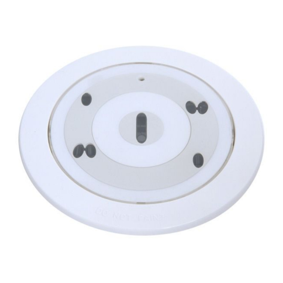
500 Series Photoelectric Detectors
FCP-500 | FCP-500-P | FCP-500-C | FCP-500-C-P
en
Installation Guide
Available from A1 Security Cameras
www.a1securitycameras.com email: sales@a1securitycameras.com
Advertisement
Table of Contents

Related Manuals for Bosch FCP-500


Summary of Contents for Bosch FCP-500
- Page 1 500 Series Photoelectric Detectors FCP-500 | FCP-500-P | FCP-500-C | FCP-500-C-P Installation Guide Available from A1 Security Cameras www.a1securitycameras.com email: sales@a1securitycameras.com...
- Page 2 Available from A1 Security Cameras www.a1securitycameras.com email: sales@a1securitycameras.com...
- Page 3 The CO sensor has not been evaluated to the requirements of UL 2075 or for its ability to detect a fire. The FCP-500-C and FCP-500-C-P detect CO as a component of a fire. Do not use the FCP-500-C and FCP-500-C-P as CO detectors.
- Page 4 . If you do not follow these cautions, the detector might not operate. Detector Location and Spacing: D BOSCH recommends spacing the sensors in compliance with NFPA-72. In low air flow applications with smooth ceilings, space sensors with a maximum distance of 30 ft. For specific information regarding sensor spacing, placement and special application refer to NFPA-72.
- Page 5 5. Turn the base counter-clockwise until the screws line up with the large end of the slots. Remove the base from the back box. Inserting Color Rings (FCP-500-C-P and FCP-500-P) 1. Select a color. 2. From the selected color, insert the largest color ring in the trim ring.
- Page 6 FCP-500 Series Table 5: Wiring Connections (Inner Ring for Conventional) Connection Terminal Wire Connection b1/b2 yellow terminals Alar Alarm m r r e e la a y y (normally open) a1/a2 white Holder for cable ties Shielding not used Indicator output...
- Page 7 FCP-500 Series Mounting the Base (FCA-500 and FCA-500-E) 1. Insert the base in the back box so that it fits over the four screws. Alignment mark 2. Turn the base clockwise until it stops to lock it in place. 3. Repeat steps 1 and 2 if you install multiple detectors in a line.
- Page 8 Note: D The FCP-500-C and FCP-500-C-P must be replaced every five years. The chemical (CO) sensor turns off at five years of operation. The LED double-flashes every 8 to 12 sec, indicating trouble, and the detector continues to function as an optical (O) detector.
- Page 9 The CO sensor has not been evaluated to the requirements of UL 2075 or for its ability to detect a fire. The FCP-500-C and FCP-500-C-P detect carbon monoxide (CO) as a component of a fire. It is not a CO detector and cannot activate an alarm in the presence of CO only. It is used to adjust the sensitivity of the smoke detector.
- Page 10 Bosch Security Systems 130 Perinton Parkway Fairport, NY 14450-9199 www.boschsecurity.us Customer Service: (800) 289-0096 Technical Support: (888) 886-6189 Available from A1 Security Cameras www.a1securitycameras.com email: sales@a1securitycameras.com...
Need help?
Do you have a question about the FCP-500 and is the answer not in the manual?
Questions and answers