
Related Manuals for Johnson Controls Mercury P2000 CKM-MR16IN


Summary of Contents for Johnson Controls Mercury P2000 CKM-MR16IN
- Page 1 P2000 Security Management System hardware installation CKM-MR16IN authentic Mercury™ terminal module 24-10707-74 Revision D December 2017...
- Page 2 If this document is translated from the original English version by Johnson Controls, all reasonable endeavors will be used to ensure the accuracy of translation. Johnson Controls shall not be liable for any translation errors contained herein or for incidental or consequential damages in connection with the furnishing or use of this translated material.
- Page 3 Declarations of Conformity United States: This equipment has been tested and found to comply with the limits for a Class A digital device, pursuant to part 15 of the FCC Rules. These limits are designed to provide reasonable protection against harmful interference when the equipment is operated in a commercial environment.
- Page 4 UNDERWRITERS LABORATORIES COMPLIANCE VERIFICATION SHEET The following model number is listed under Underwriters Laboratories® (UL) 1076 for Proprietary Burglar Alarm Units and Systems, UL 294 for Access Control Systems Units and Underwriters Laboratories of Canada ULC/ORD-C1076-86. CKM-MR16IN When installed at the site the following requirements must be met to comply with these standards. 1.
-
Page 5: Table Of Contents
CKM-MR16IN Hardware Installation Manual 24-10707-74 Rev. D CKM-MR16IN I NPUT ERMINAL ODULE This document provides hardware installation and setup instructions for CKM-MR16IN, the authentic Mercury™ terminal module. This document is divided into the following sections: • General Information on page 1 •... -
Page 6: Mounting Information
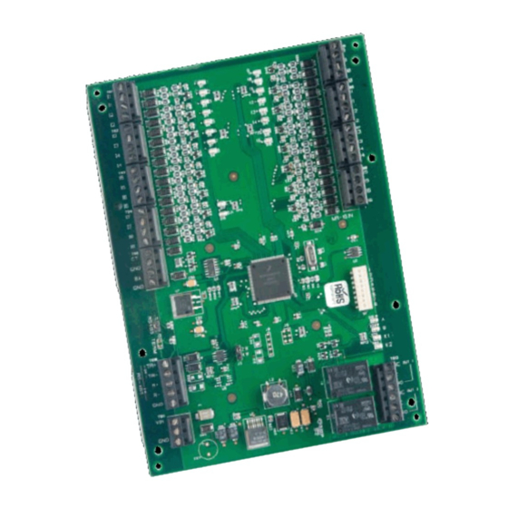
CKM-MR16IN Hardware Installation Manual 24-10707-74 Rev. D OUNTING NFORMATION 6.00 [152.40] 0.25 [6.35] 5.50 [139.70] INPUT STATUS LEDs INPUTS INPUTS MR-16IN DIP SWITCHES SIO COMMUNICATION PORT, RS-485 STATUS LEDs OUTPUTS TB10 Ø0.16 [Ø3.96] TB12 8 PLACES TB11 POWER IN 12-24Vdc Figure 1: CKM-MR16IN Hardware IRING NFORMATION... - Page 7 CKM-MR16IN Hardware Installation Manual 24-10707-74 Rev. D Cable Routing The cables should run in grounded conduit or at least two feet from AC power, fluorescent lights, or other high energy sources. : All data cables should be physically separated from power lines. If MPORTANT conduit is used, do not run data cables in the same conduit as power cables or certain door strike cables, e.g.
- Page 8 CKM-MR16IN Hardware Installation Manual 24-10707-74 Rev. D Communications Wiring The CKM-MR16IN communicates to an intelligent controller (EP2500 for example) via a two-wire RS-485 interface. The interface allows multidrop communication on a single bus of up to 4,000 feet (1,200 m). Shielded cable of 24 AWG with characteristic impedance of 120 ohm is specified for the RS-485 interface.
- Page 9 CKM-MR16IN Hardware Installation Manual 24-10707-74 Rev. D 1K,1% 1K,1% 1K,1% 1K,1% Figure 4: Alarm Contact Wiring Relay Outputs Wiring Two form-C contact relays are provided for controlling door strikes or other devices. Load switching can cause abnormal contact wear and premature contact failure.
-
Page 10: Setup Information
CKM-MR16IN Hardware Installation Manual 24-10707-74 Rev. D ETUP NFORMATION Use the Jumpers for RS-485 termination and two-wire/four-wire select. Use the Jumpers to select the device address, communication baud rate, and to enable or disable encrypted communication. All other configuration settings are set via host software. - Page 11 CKM-MR16IN Hardware Installation Manual 24-10707-74 Rev. D Table 2: Switches Selection OFF OFF OFF ON Address 17 OFF OFF ON OFF Address 18 OFF OFF ON Address 19 OFF ON OFF OFF Address 20 OFF ON OFF ON Address 21 OFF ON OFF Address 22 OFF ON...
-
Page 12: Status Leds
CKM-MR16IN Hardware Installation Manual 24-10707-74 Rev. D TATUS Table 3: LED Information Process LED Information Power-up All LEDs OFF Initialization Once you apply power, initialization of the module begins. When initialization is completed, LEDs 1 through 16, CT, BA, A, and B are briefly sequenced ON then OFF. - Page 13 CKM-MR16IN Hardware Installation Manual 24-10707-74 Rev. D Table 3: LED Information Process LED Information Running 1 LED: Input Status: 1 (continued) 2 LED: Input Status: 2 3 LED: Input Status: 3 4 LED: Input Status: 4 5 LED: Input Status: 5 6 LED: Input Status: 6 7 LED: Input Status: 7 8 LED: Input Status: 8 CKM-MR...
-
Page 14: Specifications
CKM-MR16IN Hardware Installation Manual 24-10707-74 Rev. D PECIFICATIONS Use this interface in low voltage, Class 2 circuits only. Table 4: CKM-MR16IN Specifications Category Description Primary Power 12 to 24 VDC ±10%, 350 mA maximum (plus reader current) 12 VDC at 300 mA (plus reader current) nominal 24 VDC at 220 mA (plus reader current) nominal Outputs 2 outputs, Form-C, 5A at 28 VDC, resistive... -
Page 15: Maintenance
CKM-MR16IN Hardware Installation Manual 24-10707-74 Rev. D AINTENANCE Impaired Performance The following is a list of the impaired performance conditions: • Unit environment not as specified • Unit power not as specified • Cable type and length not as specified Test Procedure To check for proper operation of the device: 1. - Page 16 CKM-MR16IN Hardware Installation Manual 24-10707-74 Rev. D...
- Page 17 Security Solutions (805) 522-5555 www.johnsoncontrols.com We welcome your comments at BE-techpubs-security@jci.com.
Need help?
Do you have a question about the Mercury P2000 CKM-MR16IN and is the answer not in the manual?
Questions and answers