Table of Contents
Advertisement
Quick Links
Safety, Operation & Maintenance Manual
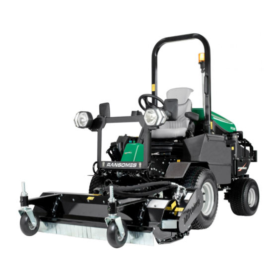
Ransomes HR380 Ride on Rotary & Flail Mower
Kubota D1803 - CR - E5
With ROPS Series: MV
Product code: 10007167
WARNING: If incorrectly used this machine can cause severe injury. Those who use and maintain this
machine must be trained in its proper use, warned of its dangers and must read the entire manual
before attempting to set up, operate, adjust or service the machine.
®
WARNING
GB
Kingdom
RJL 100 January 2021
United
10023750-GB (Rev.A)
®
Advertisement
Table of Contents

Related Manuals for Ransomes HR380


Summary of Contents for Ransomes HR380
- Page 1 ® Safety, Operation & Maintenance Manual Ransomes HR380 Ride on Rotary & Flail Mower Kubota D1803 - CR - E5 With ROPS Series: MV Product code: 10007167 WARNING WARNING: If incorrectly used this machine can cause severe injury. Those who use and maintain this machine must be trained in its proper use, warned of its dangers and must read the entire manual before attempting to set up, operate, adjust or service the machine.
-
Page 2: Table Of Contents
Horn ............................54 Warranty ..........................127 Power Outlet ..........................54 Service ............................ 127 Park Brake Release Valve......................55 Free Wheel ..........................55 Lighting Kit (Optional) ......................56 Seat Right Hand Arm Rest & Pod ....................56 ©2021 Ransomes Jacobsen Limited. All Rights Reserved... -
Page 3: Introduction 2
INTRODUCTION 2 IMPORTANT __________________________________________________________ The Ransomes HR380 is a Diesel engined self propelled mower. The hydraulic systems are for the traction drive, the cutting unit lift and the lower and cutting unit drives and steering. IMPORTANT: Do the maintenance indicated in this manual to make sure that the quality of cut is kept at a high level. -
Page 4: Product Identification
PRODUCT IDENTIFICATION ___________________________________________ Maximum front axle load in Kg (for machines being driven on the highway) West Road Ransomes Europark Unladen weight, (No cutting implements or fuel (mass) in Kg Ipswich IP3 9TT England Maximum rear axle load in Kg (for machines being driven on... - Page 5 INTRODUCTION 2 ROPS Serial Plate Ransomes Jacobsen Ltd Weight of ROPS West Road Ransomes Europark Ipswich IP3 9TT Date Code England Standard Used Part Number Used on Product Serial Number ROPS Serial Plate Location The ROPS serial plate (C) is located at the base of the front of the ROPS main beam.
-
Page 6: Guidelines For The Disposal Of Scrap Products
“General discarded materials” area. • Do not burn discarded materials. Change the machinery records to show that the machine is not in service and is discarded. Supply this serial number to Ransomes Jacobsen Limited Warranty Department to close their records. en-6... -
Page 7: Parts Manual
INTRODUCTION 2 PARTS MANUAL ______________________________________________________ In compliance with the ISO14001 standard, Ransomes Jacobsen Limited does not send a paper parts manual with every product. To refer to a parts list for this mower you have two options: Website – www.ransomesjacobsen.com. Select the “MANUALS” tab at the top, select a brand, product category and product. -
Page 8: Notes
2 INTRODUCTION NOTES en-8... -
Page 9: How To Operate Safely
Know the location and correct operation of controls. Operators without experience must receive instruction from another person that knows the correct operation of the equipment before you operate the mower. Only use parts, accessories and attachments approved by Ransomes Jacobsen Limited. 3.1.1 SAFE OPERATION __________________________________________________ Read the Operator’s Manual and other training material. -
Page 10: Operation
3 SAFETY Inspect the area where the equipment is operated. Remove all objects you can find before you operate. Be careful of obstructions above the ground (low tree limbs, electrical wires) and also underground obstacles (sprinklers, pipes, tree roots). Enter a new area carefully. Look for possible hazards. Inspect the cutting system before you start the mower. -
Page 11: Rops
Do not weld, drill, change or bend the ROPS. Replace a damaged ROPS. Do not try to correct a damaged ROPS. Do not remove the ROPS from the mower. Ransomes Jacobsen must approve any changes to the ROPS. 3.1.5 SAFE HANDLING OF FUELS___________________________________________ The fuel and the fuel vapors are flammable. -
Page 12: When You Put The Mower On A Trailer
DO NOT operate the machine if you have worn or damaged parts for safety. Replace damaged or worn decals. Only use parts, accessories and attachments approved by Ransomes Jacobsen. To decrease the fire hazard, remove materials that burn from the engine, muffler, battery tray and fuel tank area. -
Page 13: Important Safety Notes
By following all instructions in this manual, you increase the life of your machine and keep its maximum performance. Adjustments and maintenance must always be done by an approved technician. If a service is needed contact your authorized Ransomes Jacobsen Dealer or after sales for additional information or help. - Page 14 2006/42/EC Sections 3.2.2, Seating & 3.4.3, Rollover. (ANSI B71.4-2012 section 20.7) Ransomes Jacobsen Limited recommends that the owner/user of the machine completes a site specific risk assessment of the machine to find any conditions that do not follow this rule.
- Page 15 SAFETY 3 WARNING Vibration Exposure Limits Exposure limits are calculated as a combination of the vibration level (magnitude) of the tool and the Daily Exposure Time (Trigger Time). e.g. A product with 5m/s² vibration can be used up to 2 hours/day to reach the EAV and up to 8 hours/day to reach the ELV.
-
Page 16: Engine Specification
4 SPECIFICATIONS ENGINE SPECIFICATION ______________________________________________ Model: D1803-CR-E5 Type: Vertical, water-cooled, 4-cycle diesel engine Number of Cylinders Bore & Stroke 87mm x 102.4mm Total Displacement 1.826 litres Combustion Chamber Direct injection type Rated output / kW / min (rpm) 28.0 / 2700 Speed*1 (HP / min (rpm) 37.5 / 2700 Max. -
Page 17: Dimensions & Weights
SPECIFICATIONS 4 DIMENSIONS & WEIGHTS _____________________________________________ Metric Imperial Width of Cut with 152cm RD deck 152.4cm 60" Width of Cut with 183cm RD deck 182.9cm 72" Width of Cut with 160cm Flail 160cm 63" Overall Width with 152cm RD deck 164cm 64.6"... -
Page 18: Machine Specification
4 SPECIFICATIONS HR380 with MUFM160cm Flail HR380 with 152cm Rear Discharge Rotary Deck en-18... - Page 19 Rear Wheel Product Tyre Size Tyre Type Tyre Pressure Tyre Size Tyre Type Tyre Pressure HR380 OTR BKT LG306 OTR BKT LG306 26 x 12.00 -12 1.00 - 1.37 bar 20 x 10.00-8 1.00 - 1.37 bar Reinforced Tyre HR380 26 X 12.00 -12...
-
Page 20: Vibration Level
Information Supplied for Physical Agents Directive 2002/44/EC By reference to: Hand/Arm Standards: BS EN ISO 5349-1 (2001) BS EN ISO 5349-2 (2002) HR380 With 152cm Rotary Deck Series MV with ROPS Hand / Arm Acceleration Max. LH or RH Accelerations m/s²... -
Page 21: Noise Testing
SPECIFICATIONS 4 NOISE TESTING______________________________________________________ When the machine was tested for sound pressure (Operator Ear). The Machinery Safety Directive 2006/42/EC Exposure Of Workers To The Risks Arising From Physical Agents (Noise) Directive 2003/10/EC By compliance to: The Lawnmower Standard BS EN ISO 5395:2013 Sound Pressure Standard EN ISO 3746:2010 Measured Sound Pressure 88.6 dB(A) ±... -
Page 22: Rotary Deck Specification
4 SPECIFICATIONS ROTARY DECK SPECIFICATION ________________________________________ 152cm Deck 183cm Deck Construction Heavy duty welded pressed steel construction Blade Length 533mm 635mm Number of Blades Blade Tip Speed 4692m/min (2800±100rpm) 5017m/min (2515±100rpm) Width of Cut 1524mm 1828mm Height of Cut 25mm - 115mm Height of Cut Adjustment Front Castor wheels with spacers. -
Page 23: Notes
SPECIFICATIONS 4 en-23... -
Page 24: Safety Decals Ec
5 DECALS SAFETY DECALS EC__________________________________________________ 4170640 4153197 19 ° 22 ° 4324674 10024726 en-24... - Page 25 DECALS 5 009034920 Stay Clear of Hot Surfaces. 009034880 Do Not Open or Remove Safety Shields While the Engine is Running. 009034940 Caution Rotating Blades. 009034900 Do Not Remove Safety Shields While Engine is Running. 009114340 Caution Diesel Fuel. 4164860 Caution Hydraulic Oil.
-
Page 26: Instruction Decals Ec
5 DECALS INSTRUCTION DECALS EC ____________________________________________ 1 - 2 25 mm 1.0 in A [1] 31 mm 1.25 in 38 mm 1.50 in B [1] 44 mm 1.75 in A [1] + B [1] B [2] 50 mm 2.0 in A [1] + B [2] 57 mm 2.25 in... - Page 27 DECALS 5 Description Beacon Parking Brake Horn Cutting Implement PTO Drive Throttle Traction Pedal, Forward / Reverse Power socket 12 volt Height of Cut Rotary Chart Height of Cut Flail Chart Mow / Transport lever Maximum Sound Power Level Control Pod Functions Jack &...
-
Page 28: Operator Workstation
6 CONTROLS OPERATOR WORKSTATION____________________________________________ 6.11 6.13 6.12 6.18 6.16 en-28... -
Page 29: Instrument Panel
CONTROLS 6 INSTRUMENT PANEL _________________________________________________ A: Starter Key Switch Light Switch B: Throttle Control (optional) C: Park Brake Switch K: Cutting Implement D: Hazard Warning Switch Lift/Lower Control (optional) Traction Boost / Weight E: Auxiliary Hydraulic Services Transfer Switch Kit (optional) M: Deck Position Indicator Lamp F: Cutter Switch (PTO) N: Cutters (PTO) Indicator Lamp... -
Page 30: Starter Key Switch
6 CONTROLS 6.2.A STARTER KEY SWITCH ______________________________________________ The Starter Key (A) must be turned clockwise to the 'start' position to start the engine. After starting, the key must be released and allowed to return automatically to the 'on' position for normal running. NOTE:The glow plugs will auto pre-heat depending on the coolant temperature before cranking begins. -
Page 31: Cutting Unit Switch Pto
CONTROLS 6 6.2.F CUTTER SWITCH (PTO) ______________________________________________ To commence cutting ensure speed limiter is in mow position and the units have been lowered. Push bottom of the rocker switch and move joystick to- wards the lower position. To stop cutter unit rotation push top of rocker switch. Cutting units stop rotating automatically when raised or the operator leaves the seat. -
Page 32: Visual Display
6 CONTROLS VISUAL DISPLAY _____________________________________________________ The visual display is activated when the ignition is turned on. 6.3.1 STARTUP SCREEN __________________________________________________ When the Ignition Key is turned to the start position, this screen is shown. The Hour Meter will show total hours of engine operation. 2.5 Hours ®... -
Page 33: Home Screen
If TST™ is not installed the TST™ icon will be crossed through. Ransomes Jacobsen recommends that the owner/user of the machine completes a site specific risk assessment of the area to be mown prior to operation of the machine. -
Page 34: Home Screen
6 CONTROLS 6.3.6 HOME SCREEN _____________________________________________________ The Home Screen will give the operator alternative button functions when Button 4 has been pressed once 02:01 3.4 Hours Buttons numbered left to right: ® Button 1:DPF Regen Start Button 2:DPF Regen Inhibit *Note - Refer to section 8.14 Diesel Particulate filter for full details. -
Page 35: Fault Log
CONTROLS 6 FAULT LOG _________________________________________________________ The first page within the Fault Log makes it possible to see any Fault Popup Warnings that have occurred and been cleared, that are however still active. Button 2 & 3 can be used to scroll through if there is more than one, Button 1 exits to the Service Menu. -
Page 36: Time Until Service
6 CONTROLS 6.4.1 TIME UNTIL SERVICE ________________________________________________ This screen gives the number of engine hours until the next service inspection is required. Time Until Service To reset the service interval press & hold Button 2, 3 & 4 until the figure changes. -
Page 37: General
Engine Ignition Key Input Main Controller c1p10 Park Brake Switch Input Main Controller c1p19 Hydraulic Oil Level Switch Input Not used on HR380 Main Controller c1p31 Engine Run Interlock Output Expansion Module c2p03 Reverse Beeper Output Not used on HR380... -
Page 38: Implements
6 CONTROLS Implements Ref Module Function Note Number c1p09 Left Hand Joystick Input Not used on HR380 Main Controller c1p16 Left Hand Position Sensor Input Not used on HR380 Expansion Module c2p04 Left Hand Float Solenoid Output Not used on HR380... -
Page 39: Cutters
Pin Number Function Note c1p07 Cutter Switch (PTO) Input Not used Main Controller c1p18 Transport Lock Switch Input on HR380 Not used Main Controller c1p40 Left Hand Cut Solenoid Output on HR380 Not used Expansion Module c2p06 Left Hand Transport Lock Solenoid Output... -
Page 40: Traction
Note Main Controller c1p07 Cutting Circuit Pressure Switch Input Main Controller c1p24 Right Hand Wheel Speed Sensor Input Not used on HR380 Main Controller c1p27 Traction Pedal Signal B Input Not used on HR380 Main Controller c1p42 EDC Coil Forwards Output... -
Page 41: Main Controller Miscellaneous Pins
CONTROLS 6 Main Controller Miscellaneous Pins Module Pin Number Function Note Main Controller c1p01 Battery Negative Main Controller c1p04 CAN 0 Low Main Controller c1p09 Sensor Power Ground Main Controller c1p22 CAN 1 Shield Main Controller c1p49 Battery Positive Main Controller c1p02 Battery Positive Main Controller... -
Page 42: Main Controller Miscellaneous Pins Continued
6 CONTROLS Miscellaneous Pins Continued Module Pin Number Function Note Expander Module c1p01 Battery Negative Not used on HR380 Expander Module c1p04 CAN 0 Low Not used on HR380 Expander Module c2p11 Battery Positive Not used on HR380 c1p01 Battery Negative... -
Page 43: Settings
This screen gives access to the following parameters and machine functions that can be altered: • Cross Cut • Traction Boost • Inclinometer • Set Default Parameters • Change PIN The default owner’s Pin is 1001, however Ransomes Jacobsen recommend this is changed. en-43... -
Page 44: Cross Cut
6 CONTROLS 6.5.3 CROSS CUT ________________________________________________________ Cross Cut function raises the cutting implement to a partially raised posi- tion, allowing the operator to avoid obstructions without having to fully lift the cutter deck. The Cutter PTO will disengage within 3 seconds of reach- Cross Cut ing Cross Cut position. -
Page 45: Reset Default Parameters
CONTROLS 6 6.5.6 RESET DEFAULT PARAMETERS _______________________________________ The machine will have factory set defaults. You can reset to factory settings by Using the PIN Menu Set Default Parameters Set Default Parameters Buttons 2 and 3 to arrow up and Press To Confirm Set Press To Confirm Set... -
Page 46: Warning Screens
6 CONTROLS WARNING SCREENS__________________________________________________ When malfunctions occur, the following warning screens are displayed. 6.6.1 SLOPE ANGLE DISPLAY______________________________________________ During work, if the machine is driven on a slope of 16° the machine angle will be displayed in the centre of the screen, until the machine has been 1234 123.4 Hours driven onto an area of less than 16°. -
Page 47: Warning Slope Angle - Inhibit Cut
1000 rpm. Stop the engine and check the oil level. Top up if necessary. If the fault persists, do not use the machine at all and contact your local Ransomes Jacobsen dealer. 6.6.6 WARNING ENGINE OVERHEAT ________________________________________ When this screen is shown, the engine... -
Page 48: Warning Engine Fault
6.6.7 WARNING ENGINE FAULT ____________________________________________ When this screen is shown, there is an engine fault. Stop the engine as soon as possible and contact your local Ransomes Jacobsen Dealer. When this fault occurs the machine’s engine may automatically reduce the power available. -
Page 49: Warning Tilt Sensor Technology (Tst™) Fault
6.6.11 WARNING TILT SENSOR TECHNOLOGY (TST™) FAULT________________ When this screen is shown, there is a fault with the TST™. Stop as soon as possible and contact your local Ransomes Jacobsen Dealer. 6.6.12 JOYSTICK FAULT _______________________________________________ When this screen is shown, there is a fault with the Unit Lift/Lower Control. -
Page 50: Emission Fault - Maf Sensor
When this screen is shown, the engine controller (ECU) is reporting that the level of ash in the DPF (Diesel Particulate Filter) is in excess of 95% and therefore the DPF needs to be serviced. Contact your local Ransomes Jacobsen Dealer for information on the procedure for servicing the DPF. >95% 6.6.18... -
Page 51: Mcu / Display Communication Fault
MCU / DISPLAY COMMUNICATION FAULT ___________________________ When this screen is shown, there is a communication fault with the machine controller (MCU) and/or display. Stop the engine as soon as possible and contact your local Ransomes Jacobsen Dealer. 101010 IMPLEMENT LIFT / LOWER SWITCH _____________________________________ To lower the lift arms move the switch lever forward. -
Page 52: Implement Position & Performance Indicator Lamp
6 CONTROLS IMPLEMENT POSITION & PERFORMANCE INDICATOR LAMP _______________ The lamp (M) illuminates green when the cutting implement is lowered to the ground and illuminates amber when the drive is stalling. If this happens the forward speed of the machine must be reduced until the lamp goes out. -
Page 53: Traction Pedal
CONTROLS 6 6.11 TRACTION PEDAL____________________________________________________ DRIVING 1.Release Brake - Make sure the Park Brake is released before you try to go forward or reverse. 2.Forward - Carefully push the top (A) of the Forward / Reverse Foot Pedal to reach correct ground speed. 3.Reverse - Carefully push the bottom (B) of the Forward / Reverse Foot Pedal to reach correct ground speed. -
Page 54: Steering Tilt Control
6 CONTROLS 6.12 STEERING TILT CONTROL _____________________________________________ When the operators seat is in the correct position to operate the Traction Pedal comfortably, push the small Foot Pedal (A) at the base of the steering column, and tilt the column backward or forward to the correct position. -
Page 55: Park Brake Release Valve
CONTROLS 6 6.15 PARK BRAKE RELEASE VALVE_________________________________________ The Park Brake Release Valve is situated under the seat plate, on the right hand chassis plate. It is used to release the parking brake when the engine is not running To release the Parking Brake, •... -
Page 56: Lighting Kit (Optional)
6 CONTROLS 6.17 LIGHTING KIT (OPTIONAL) ____________________________________________ Lighting Control Stalk No function. Pull towards operator to flash headlights. Move stalk down to indicate left turn. Move stalk up to indicate right turn. Horn NOTE: Daylight Running Lamps (DRLS) will operate when ignition is in the run position When the lighting kit is fitted a brake light function is available. - Page 57 CONTROLS 6 en-57...
-
Page 58: Daily Inspection
7 OPERATION DAILY INSPECTION_________________________________________________ CAUTION The daily inspection should be performed only when the engine is off and all fluids are cold. Lower implements to the ground, engage Park Brake, stop engine and remove Ignition Key. 1. Perform a visual inspection of the entire machine, look for signs of wear, loose hardware and missing or dam- aged components. -
Page 59: Operating Procedure
OPERATION 7 Cutter Engage Test Operator Seated Traction Pedal Park Brake Switch Engine Starts (PTO) Switch Out of Neutral Neutral Lift your weight off the seat. The cutting implement PTO will disengage within 3 seconds. Lift your weight off the seat. The engine must stop after 3 seconds. OPERATING PROCEDURE________________________________________________ WARNING Never operate the equipment with the operator presence... -
Page 60: Interchanging Cutter Decks
7 OPERATION CAUTION Remove all debris from the site before mowing. Enter a new area cautiously always operate at speeds that allow you to have complete control of the mower CAUTION Before you clean, adjust, or repair this equipment, always disengage all drives, lower implements to the ground, engage Park Brake, stop engine and remove key from Ignition Switch to prevent injuries... - Page 61 OPERATION 7 3.Connect the deck hoses to the machine by either – a. Attaching the hard routed motor hoses directly to the Cutter Valve (ensure the hoses are routed through the Guide Loop) i. The hose from the LH motor connects to the Cutter Valve port A ii.
-
Page 62: Fitting The Mufm 160Cm Flail To The Machine
7 OPERATION 7.4B FITTING THE MUFM 160CM FLAIL TO THE MACHINE ____________________ Note: That it is important to ensure that the machine has been fitted with the correct flail deck lift arms, counterweights and bump stops prior to attaching the flail. 1. -
Page 63: Operating The Machine For The First Time
OPERATION 7 OPERATION OF THE MACHINE _______________________________________ Read the Safety Instructions. BEFORE OPERATING FOR THE FIRST TIME • Check and adjust tyre pressure, if necessary, see section 4.3 Specification. • Add diesel fuel to tank if necessary. • Check engine oil and top-up, if necessary. •... -
Page 64: Mowing
7 OPERATION MOWING__________________________________________________________ 1. Ensure speed limiter is in mow position. 2. Lower the cutting implement. 3. Engage the cutting mechanism by pressing the cutting PTO switch forward. 4. Release the Park Brake and begin driving forward. NOTE: Always set the throttle to full engine revs for mowing, even when the grass is heavy. When the engine is labouring, reduce forward speed by easing back on the FWD/REV foot pedal. -
Page 65: Transporting On A Trailer Or Flat Bed
OPERATION 7 7.11 TRANSPORTATION ON A TRAILER OR FLATBED _______________________ 1. The machine has tie-down loops front (A) and rear (B). Fasten the mower to the transport vehicle. 2. Make sure that all tie down straps are tight. Make sure that the implements are locked in the transport posi- tion. -
Page 66: Mowing On Slopes
7 OPERATION 7.12 MOWING ON SLOPES ______________________________________________ The mower has been designed for good traction and stability under normal mowing conditions. Use caution when operating on slopes, especially when the grass is wet. Wet conditions reduces traction and steering control. WARNING To minimize the possibility of overturning, the safest method for operating on hills and terraces... - Page 67 ROPS to comply with the Machinery Directive 2006/42/EC sections 3.2.2, Seating & 3.4.3, Rollover Ransomes Jacobsen Limited recommends that a local risk assessment is completed by the owner/ user of the machine to determine the risks associated with working on slopes.
-
Page 68: Maintenance And Lubrication
8 MAINTENANCE AND LUBRICATION MAINTENANCE & LUBRICATION CHART ____________________________ GENERAL MAINTENANCE AND LUBRICATION CHART Interval Item Section First 50 hours Visual inspection for damage or wear Check blade condition Change Hydraulic Charge Filter Element or earlier if screen indicates. - Page 69 MAINTENANCE AND LUBRICATION 8 8.11 en-69...
-
Page 70: Engine Service Interval
8 MAINTENANCE AND LUBRICATION 8.1.1 ENGINE SERVICE INTERVAL ______________________________________ ENGINE SERVICE INTERVAL CHART Interval Item Section Daily 8.2.1 Check engine oil level. 10 hours Check fuel level. 6.3.2 Check coolant level. Check auxiliary belt tension. Press together the air cleaner dust valve. - Page 71 MAINTENANCE AND LUBRICATION 8 Interval Item Section Replace oil separator related rubber piping. Replace DPF related rubber piping. Replace intake air line and suction air pressure takeout rubber piping. Replace boost sensor pressure rubber piping. Replace EGR cooler rubber piping.
-
Page 72: Flail Service
8 MAINTENANCE AND LUBRICATION 8.1.2 FLAIL SERVICE ______________________________________________________ FLAIL UNIT SERVICE INTERVAL CHART Interval Item Section First hour of Drive belt tension operation Check all fasteners, replace all missing hardware Visually inspect implement Once Daily Lubricate rotor and roller bearings ... -
Page 73: Tensioning
MAINTENANCE AND LUBRICATION 8 8.1.4 TENSIONING __________________________________________________________ • Loosen the nuts but do not remove them. Nuts Bolt • Loosen the lock nut. Release • Use the bolt to set the V-belt tension, This can be checked via the inspection opening. When pressed Counterweight under a load of 6kg the V-belt must not be able to move more than 10mm. -
Page 74: Replacement
8 MAINTENANCE AND LUBRICATION 8.1.5 REPLACEMENT ______________________________________________________ If there are any tears or other damage on the V-belt, it Bolt must be replaced. • Remove the screws, remove the safety cover. Screws Safety cover Bolt • Loosen the lock nuts. Bolt •... -
Page 75: Flail Heads
MAINTENANCE AND LUBRICATION 8 Secure the machine Work can only be carried out on a machine secured against rolling away and dropping. To prevent drop- ping, for example, permitted and correctly dimensioned support legs can be used. If the machine is not secured against rolling away and lowering, serious or fatal accidents could result. If the skids also need to be replaced on the opposite side: •... -
Page 76: Engine
The operation and maintenance during the first 50 hours of a new engine can make a difference to the performance and life of the engine. During the first 50 hours of operation, Ransomes Jacobsen recommends the following. • Allow the engine to reach a temperature of at least 60° C (140° F) before operation at full load. -
Page 77: Engine Lubrication
MAINTENANCE AND LUBRICATION 8 8.2.1 ENGINE LUBRICATION ___________________________________________ Check Engine Oil Level Check the engine oil level before you start or at least five minutes after you stop the engine. Park the machine on level ground, remove the dipstick (A), clean with a cloth and replace in position. -
Page 78: Engine Auxiliary Belt
8 MAINTENANCE AND LUBRICATION ENGINE AUXILIARY BELT __________________________________________ Check and adjust the auxiliary belt The auxiliary belt tension is adjusted to prevent the stress on the alternator bearings and to prevent movement on the alternator pulley. Use the procedure shown below to check the belt tension at the center of the belt between crank shaft and alternator pulleys. - Page 79 Replace the clamps and hoses (see maintenance chart). Have your Ransomes Jacobsen Dealer check the cooling system if you need to add coolant more than one time a month or you add more than a litre of coolant at a time.
-
Page 80: Hydraulic System
8 MAINTENANCE AND LUBRICATION HYDRAULIC SYSTEM ______________________________________________ Check hydraulic oil level using sight gauge (C). Change Hydraulic Oil (a) Clean around hose (A) in bottom of Hydraulic tank and remove. (b) Allow tank to drain into a suitable container and replace hose. -
Page 81: Hydraulic System Flushing
All tests, unless stated otherwise, must be carried out with the hydraulic oil at normal working temperature. TEST PORT Steering and lift pressure 125 bar. NOTE: Any hydraulic related issues contact your Ransomes Jacobsen dealer for a full fault diagnosis. en-81... -
Page 82: Decals Fuel
8 MAINTENANCE AND LUBRICATION FUEL _____________________________________________________________ Diesel fuel is flammable. Use caution when you add the fuel to the mower. Only use an approved container. The spout on the container must fit inside the fuel filler neck. Never use the containers that are not approved to keep or transfer fuel. -
Page 83: Fuel System
MAINTENANCE AND LUBRICATION 8 FUEL SYSTEM _____________________________________________________ Use Diesel to B.S. EN590 or ASTM D975 (Ultra Low Sulfur) Water separator If water is not removed from the fuel, damage to the fuel-injection system can occur. When water in fuel icon is displayed or at service interval, drain the water from the water separator. -
Page 84: Fuel Pickup Filter
8 MAINTENANCE AND LUBRICATION 8.9.1 FUEL PICKUP FILTER _______________________________________________ It is advisable that the Fuel Pickup Mesh Filter (A) is cleaned on a periodic basis. Should the machine exhibit fuel starvation issues then the Mesh Filter should be checked and cleaned for contamination. To clean the Filter Mesh, Unscrew the Fuel Pickup cap and withdraw the Fuel Pickup Sender unit. -
Page 85: Battery
MAINTENANCE AND LUBRICATION 8 8.11 BATTERY _________________________________________________________ Before you service the battery, make sure the ignition switch is in the OFF position and the key is removed. CAUTION When you service the battery, always use the tools with insulation, wear protective glasses and protective clothing. -
Page 86: Charge The Battery
8 MAINTENANCE AND LUBRICATION 8.12 CHARGE THE BATTERY ____________________________________________ WARNING Charge the battery in an area with good airflow. The battery can release hydrogen gas that is explosive. To prevent an explosion, keep any device that can cause sparks or flames away from the battery. When the battery charger is turned on, to prevent injury, stay away from the battery. -
Page 87: Diesel Particulate Filter
MAINTENANCE AND LUBRICATION 8 8.14 DIESEL PARTICULATE FILTER ______________________________________ During operation of the mower, the level of particle material will increase in the Diesel Particulate Filter (DPF) system. The periodic Regen of the DPF system is needed to remove particle material. During an Active or Parked Regen, the engine will use more fuel. -
Page 88: Hydraulic Hoses
8 MAINTENANCE AND LUBRICATION 8.15 HYDRAULIC HOSES _______________________________________________ WARNING To prevent injury from the hot, high pressure oil, never use your hands to check for oil leaks. Use paper or cardboard to find leaks. The hydraulic fluid pressure can have enough force to enter your skin. If hydraulic fluid has entered your skin, please seek medical attention as soon as possible. -
Page 89: Wheel Mounting Procedure
MAINTENANCE AND LUBRICATION 8 8.17 WHEEL MOUNTING PROCEDURE ____________________________________ WARNING Make sure the mower is parked on a solid and level surface. Never work on a mower that is supported only by the Jack. Always use Axle Stands. If only the front or rear of the mower is lifted, put the chocks in front of and behind the wheels that are not lifted. -
Page 90: Rear Hub Nut Lock- Application And Inspection
8 MAINTENANCE AND LUBRICATION 8.18 REAR HUB NUT LOCK / APPLICATION AND INSPECTION _________________ The Hub Nut Lock is a quick visual indicator to the security of the Hub Nut. Due to its design and colouring the Hub Nut Lock is easily visible from a distance even when the tractor unit is in use or is parked. -
Page 91: Machine Maintenance
MAINTENANCE AND LUBRICATION 8 8.20 MACHINE MAINTENANCE __________________________________________ Other Regular Service • Verify proper operation of safety interlock switches (Seat switch, etc.) • Ensure nuts and bolts remain tight. • visually inspect for hydraulic leaks. • Keep engine bay clear of debris. •... -
Page 92: Notes
8 MAINTENANCE AND LUBRICATION en-92... -
Page 93: Traction Control Pedal
ADJUSTMENTS 9 TRACTION CONTROL PEDAL______________________________________ The LPV transmission pump has an internal neutralising mechanism which cannot be adjusted. If the machine does however creep carry out the following. Lift and support both front and rear wheels. Remove ball joint from pump lever to allow pump to neutralise. -
Page 94: Height Of Cut Rotary
9 ADJUSTMENTS 9.3A HEIGHT OF CUT _________________________________________________ Cutting height for decks can be adjusted from 25-120mm. Actual cutting height may vary somewhat from the heights given depending on turf conditions and other factors. Note: When cutting undulating areas, lower cutting heights may cause scalping. Adjust height accordingly to prevent turf damage. -
Page 95: Height Of Cut Flail
ADJUSTMENTS 9 9.3B HEIGHT OF CUT FLAIL ___________________________________________ • Secure the carrier vehicle so that it cannot roll away. • Raise the flail implement approximately 5 cm. • Adjust the front support wheels to the desired height of cut as described by the table. Shallower working depth Tools must not come into contact with the ground Cotter pin... -
Page 96: Blade Change
9 ADJUSTMENTS BLADE CHANGE ________________________________________________ Raise the deck so it is just clear of the ground. This will allow the setting pin D to lift clear of the arm and be easier to remove. Remove the pins at position D on both sides of the machine which lock the deck in its working position. -
Page 97: Rotary Blade & Balancing
For greatest safety always use genuine replacement blades. • Do not file or grind the blades lower edge to create a pointed edge, grind the top surface only to sharpen the blade. • Use a genuine Ransomes blade to ensure the original specification is maintained. en-97... -
Page 98: Shackle 'M' Carbide Flail Blade Maintenance
9 ADJUSTMENTS 9.5B SHACKLE "M" CARBIDE FLAIL BLADE MAINTENANCE _______________ Inspect the blades for free movement prior to using this mower. When, you replace blades they must be replaced as opposed pairs (B) to maintain balance. When fitting blades, tighten the nut (C) first until finger tight then torque to 9.9 Nm (7.3 ft.lb). WARNING Inspect and replace immediately any flails, lugs and retaining hardware that show any indication of cracks, heavy damage or more than expected wear. -
Page 99: General Instructions For Grammer Seats
ADJUSTMENTS 9 GENERAL INSTRUCTIONS FOR GRAMMER SEATS____________________ • The operating instructions must be read in full before use. • The driver’s seat may only be fitted, serviced and repaired by specialist personnel, In accordance with national regulations and the vehicle manufacturer’s fitting instructions. •... - Page 100 9 ADJUSTMENTS After removal of the backrest upholstery, the backrest frame must be supported, for example held in place, before the backrest adjuster is operated. If you fail to do so, there is a danger that the backrest frame may jerk forward and cause injury.
-
Page 101: Seat (Grammer Msg85)
ADJUSTMENTS 9 SEAT (GRAMMER MSG85) ________________________________________ WARNING The Operator Weight must be set to the actual weight of the Operator. Safety Systems will be compromised if this is not done. The seat can be adjusted for operator's weight and leg reach to provide a comfortable position for operating the machine. -
Page 102: Air Suspension Seat (Grammer Msg75-521)
9 ADJUSTMENTS AIR SUSPENSION SEAT (GRAMMER MSG75-521) _____________________ 9.9.1 WEIGHT ADJUSTMENT ___________________________________________ The seat is adjusted for the driver’s weight by pulling or pressing the lever for seat weight adjustment and with the driver sitting on the seat. The driver’s weight is adjusted correctly when the arrow is in the middle clear area of the viewing window. -
Page 103: Backrest Extension
ADJUSTMENTS 9 9.9.3 BACKREST EXTENSION __________________________________________ The backrest extension can be individually adjusted by pulling it upwards or pushing it downwards over the various locking increments up the end stop. To remove the backrest extension, pull it upwards over the end stop. 9.9.4 LUMBAR SUPPORT ______________________________________________ The lumbar support increases both the seating comfort... -
Page 104: Armrest Adjustment
9 ADJUSTMENTS 9.9.6 ARMREST ADJUSTMENT * ________________________________________ The inclination of the armrests can be modified by turning the adjustment knob. When turning the knob to the outside (+) the front part of the armrest will be lifted, when turning the knob to inside (-) it will be lowered. - Page 105 ROPS to comply with the Machinery Directive 98/37/EC Sections 3.2.2, Seating & 3.4.3, Rollover. Ransomes Jacobsen Limited recommends that a local risk assessment is completed by the owner/ user of the machine to determine any exceptions to this seat belt wearing rule.
-
Page 106: 10 Accessories
10 ACCESSORIES 10.1 152CM REAR DISCHARGE DECK __________________________________ Kit number – 10004593 (Without Quick Release Hydraulic Connections) Quick Release Hydraulic Conversion Kit for 152cm deck – 10024805 ‘Cut & Clear’ Conversion Kit for 152cm deck – 10024657 Note – Quick Release Conversion Kit needs to be used in conjunction with Tractor Quick Release Hydraulic Conversion Kit 10024804. -
Page 107: Cm Deck Mulching Kit
ACCESSORIES 10 10.4 152CM DECK MULCHING KIT ______________________________________ Kit number 10024368 10.5 183CM DECK MULCHING KIT ______________________________________ Kit number 10027122 en-107... -
Page 108: Cm Rear Discharge Deck
10 ACCESSORIES 10.6 ROTARY BEACON KIT ____________________________________________ Kit number 697777 - Standard 10013230 - R65 Compliant. 10.7 LIGHTING KIT ___________________________________________________ Kit Number 10009425 (UK) & 10013203 (EU) - for 152cm decks. Kit Number 10013215 (UK) & 10013224 (EU) - for 183cm decks + 160cm flail. en-108... -
Page 109: Storage Rack Kit
ACCESSORIES 10 10.8 STORAGE RACK KIT _____________________________________________ 10009150 Kit number Maximum capacity per rack is 5kg. 10.9 STORAGE POD__________________________________________________ 10002555 Kit number en-109... -
Page 110: Auxiliary Hydraulic Services Kit
10 ACCESSORIES 10.10 AUXILIARY HYDRAULIC SERVICES KIT _____________________________ Kit number 10027120 Fitting Instructions 24836G This kit is for use with approved third party attachments. Refer to price list for details. 10.11 TILT SENSOR TECHNOLOGY (TST™) _______________________________ TST™ kit number 10009298 en-110... - Page 111 ACCESSORIES 10 en-111...
-
Page 112: 11 Problem Solving
11 PROBLEM SOLVING 11.1 PROBLEM SOLVING GENERAL____________________________________ Symptoms Possible Causes Action Glow plug has not timed out Reset ignition switch and allow glow plug to time out before cranking engine. Battery low on charge or Inspect condition of battery and battery connections. defective. -
Page 113: Quality Of Cut 12
QUALITY OF CUT 12 12.1 QUALITY OF CUT PROBLEM SOLVING ______________________________ If required perform a “test-cut” to assess the The following items must be checked and set correctly to performance of the mower before you begin the make sure of an effective assessment. repairs. -
Page 114: Step Cutting
12 QUALITY OF CUT 12.2 STEP CUTTING __________________________________________________ “Step cutting” occurs when the grass is cut higher on one side. The cause is mechanical wear or incorrect setting of the roller or deck caster. TN0221 NOTE: Arrow indicates direction of travel. Possible Cause Correction The HOC (height-of-cut) settings are different on the... -
Page 115: Scalping
QUALITY OF CUT 12 12.3 SCALPING _____________________________________________________ “Scalping” is a condition in which some areas are cut shorter than the set height of cut. This results in very short grass or brown areas. The cause is a low height-of-cut (HOC) setting, rough surface. TN0222 NOTE: Arrow indicates direction of travel. -
Page 116: Stragglers
12 QUALITY OF CUT 12.4 STRAGGLERS __________________________________________________ “Stragglers” are separated blades of incorrectly cut grass. TN0223 NOTE: Arrow indicates direction of travel. Possible Cause Correction The cutting blades are blunt. Replace or sharpen blades. Cutting Speed to fast for grass conditions. Decrease the cutting speed. -
Page 117: Streaks
QUALITY OF CUT 12 12.5 STREAKS ______________________________________________________ A streak is a strip of longer grass in the cutting area. The cause is a damaged blade. TN0224 NOTE: Arrow indicates direction of travel. Possible Cause Correction Damaged or worn blades. Replace the blades. Blades fitted incorrectly. -
Page 118: Windrowing
Mow more often or raise the height of cut. one pass. Try high lift blades. Incorrect blade choice. Use original Ransomes blades: Low Lift, High Lift or Eliminator blades. Damaged baffles. Check for damage, repair/replace. Mowing while grass is very wet. -
Page 119: Clumping
QUALITY OF CUT 12 12.7 CLUMPING _____________________________________________________ “Clumping.” This problem is identified by the appearance of clumps of grass in the discharge area. TN1281 Possible Cause Correction Front edge of deck bulldozing grass between front Move the castor wheels to the outer edges of the castor wheels and anti-scalp rollers. -
Page 120: Insufficient Mulching
12 QUALITY OF CUT 12.8 INSUFFICIENT MULCHING ________________________________________ “Insufficient Mulching.” This problem is identified by long lengths of cut grass not sufficiently chopped. Mulched Non Mulched TN1280 Possible Cause Correction Incorrect blades fitted. Ensure standard low lift blades are fitted Try Shredder blades. -
Page 121: Inconsistent Uncut Patches
QUALITY OF CUT 12 12.9 INCONSISTENT UNCUT PATCHES _________________________________ “Insufficient Mulching.” This problem is identified by long lengths of random clumps of uncut grass. TN1278 Possible Cause Correction Damaged or missing blades. Check and replace damaged blades or try Eliminator blades. Extreme volume of grass is not discharged quickly Consider using a cut and clear kit enough from the deck. -
Page 122: Torn Crowns
12 QUALITY OF CUT 12.10 TORN CROWNS _________________________________________________ “Torn Crowns” This problem is identified when clumps of grass (Crowns) are torn up rather than cut. TN1234 Possible Cause Correction Too much material. Cut more frequently, increase HOC. Worn blade edge. Sharpen or Replace damaged blades. -
Page 123: Laying Uncut Grass
QUALITY OF CUT 12 12.11 LAYING UNCUT GRASS __________________________________________ “Laying uncut grass.” This problem is identified by areas of grass that have been left uncut and laid flat. TN1234 NOTE: Arrow indicates direction of travel. Possible Cause Correction Mowing (ground) speed is too fast. Cut more frequently, increase HOC. -
Page 124: Electrical Fuses & Relays
13 SCHEMATICS 13.1 ELECTRICAL FUSES & RELAYS ___________________________________ Replacement Fuses Fuse Tester 5A 7.5A 10A 15A 20A 25 Fuse Removal Tool B/LAP SPARE ENGINE FLASHER IGNITION GLOW PLUGS START TESTING A FUSE In the top right hand corner there is a tool that can be used to remove a fuse from its location. - Page 125 15 Amp Spare 5 Amp Not Used RELAY RATING FUNCTION 40 Amp Engine Master Relay 70 Amp Ignition Relay 70 Amp Glow Plug Relay 40 Amp Starter Relay 40 Amp Flasher Relay (Optional) Spare Backlap Relay (Not used on HR380) en-125...
-
Page 126: Torques
14 TORQUES TORQUES ______________________________________________________ FINE PITCH METRIC THREADS COARSE PITCH METRIC THREADS Grade Grade Grade Grade Grade Grade Grade Grade Grade Grade (mm) 10.9 12.9 (mm) 10.9 12.9 (Nm) (Nm) (Nm) (Nm) (Nm) (Nm) (Nm) (Nm) (Nm) (Nm) 1055 1266 1152 1327 1593... -
Page 127: Guarantee 15
GUARANTEE 15 GUARANTEE ___________________________________________________________ WARRANTY Warranty is subject to specific terms and conditions, e.g. wearing parts, unapproved modifications, etc. are not included. For a full set of warranty conditions, contact your local dealer or distributor. NOTICE The use of components not provided by the manufacturer under this warranty or maintenance or repair that is improperly or incorrectly performed may void this warranty. - Page 128 Cert No. EMS609276 Cert No. OHS609277 United Kingdom & Rest of The World Except North & South America & Europe Ransomes Jacobsen Limited West Road, Ransomes Europark, Ipswich, IP3 9TT English Company Registration No. 1070731 www.ransomesjacobsen.com Europe Ransomes Jacobsen France...
Need help?
Do you have a question about the HR380 and is the answer not in the manual?
Questions and answers