
Related Manuals for ISA GELATOSHOW 2


Summary of Contents for ISA GELATOSHOW 2
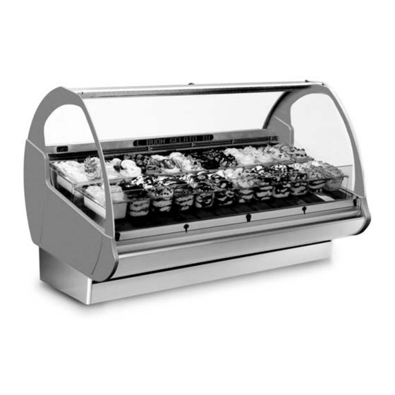
- Page 1 GELATOSHOW ISA S.r.l. Via del Lavoro, 5 06083 Bastia Umbra - Perugia - Italy Tel. +39 075 80171 - Fax +39 075 8000900 www.isaitaly.com GELATOSHOW USE AND MAINTENANCE MANUAL 428000485237...
-
Page 2: Table Of Contents
1. MANUFACTURER ..... 4 2. WARRANTY TERMS AND CONDITIONS ... . . 4 3 EQUIPMENT IDENTIFICATION . - Page 3 The manual contains symbols to attract the reader's attention and highlight particularly important aspects. The table below illustrates the meaning of the various symbols used. Read the instruction manual Use of protective clothing Danger: Live electrical parts Requests for maintenance or operations must be carried out by qua- lifi...
-
Page 4: Manufacturer
1. MANUFACTURER ISA S.r.l. Via del Lavoro, 5 06083 - Bastia Umbra - Perugia - Italy Tel. +39 075 80171 Fax +39 075 8000900 www.isaitaly.com 2. WARRANTY TERMS AND CONDITIONS The seller guarantees the equipment for 12 (twelve) months from the date of delivery. -
Page 5: Equipment Identification
3. EQUIPMENT IDENTIFICATION • Find the label affi xed on the machine to read the technical data. • Check the machine model and the power supply voltage before you perform any operation. • If you uncover mismatches, contact the manufacturer or the company that supplied the machine immediately. -
Page 6: Use
4. USE This appliance is exclusively intended to display and sell ice cream. The manufacturer is not liable for injury to persons or damage to property or the appliance itself caused by the displaying of products other than those described above. Never use electric devices inside this appliance. -
Page 7: Notes/Important Notes
Keep this manual in a safe place. It should be available for consultation near the equipment at all times. If lost or destroyed, you can request a copy of the manual from ISA S.r.l. by specifying the exact model, serial number and year of manufacture. The manual refl ects the manufacturing technology at the time of supply. - Page 8 INTRODUCTION ISA S.r.l. uses the best quality materials and their introduction on company premises, storage and use in production is continuously controlled to ensure the absence of damage, deterioration or malfunction.
-
Page 9: Safety
6. SAFETY The appliance is equipped with safety devices: 6.1 SAFETY DEVICES INSTALLED Devices whose operation prevents the occurrence of risk situations in operating conditions (e.g. fuses, pressure switches, protections, magnet circuit breakers, etc.). 6.2 FIXED GUARDS Fixed protective devices consist of fi xed perimeter shields, which are used to prevent access to the internal parts of the machine. -
Page 10: Fire
6.6 FIRE Danger In the event of a fi re, immediately disconnect the master switch from the main power supply line. 6.7 EXPLOSIVE ATMOSPHERE The equipment must not be located in an area classifi ed as an explosion risk according to 1999/92/EC such as: Zone 0 An area in which there is a permanent, long-lasting or frequently explosive atmosphere made up of a... -
Page 11: Refrigerantss (Where Applicable)
6.13 REFRIGERANTS (where applicable) REFRIGERANT DESCRIPTION The refrigerant R290 is a gas that is compatible with the environment, but highly fl ammable. Pay close attention during transport, installation and that the destruction not to damage the refrigerant pipelines. IN THE EVENT OF DAMAGE: Keep fl... -
Page 12: Disposal Of Waste Material
7. DISPOSAL OF WASTE MATERIAL During normal operation, the appliance does not generate any environmental contamination. At the end of its life cycle, or if it is necessary to proceed to permanent decommissioning, we recommend following the procedures below: DISPOSAL (User) The symbol, applied to either the product or its packaging, indicates that the product should not be considered as normal domestic waste, but should be taken to a waste collection point for the recycling of electrical and electronic appliances. -
Page 13: Installation
8. INSTALLATION This manual supplies the information necessary for correct unpacking, procedures for positioning and connection to mains electricity. 8.1 STORAGE AND UNPACKING The appliance, with or without the packaging, should be carefully stored inside warehouses or in areas away from the elements and direct sunlight, at a temperature between 00 and +40 °C. The appliance should only be moved by qualifi... -
Page 14: Maintenance
9. MAINTENANCE The Staff in charge of the appliance must control and respect the expiry dates for maintenance, given in the table below, calling the authorised Technical After-sales assistance when indicated. OPERATION FREQUENCY AUTHORISED PERSONNEL Cleaning the external surfaces Depending upon Use and Necessity User Cleaning the accessible internal parts Depending upon Use and Necessity... -
Page 15: Faults - Technical After-Sales Assistance
Assistance If the control unit is set up especially for must R290 refrigerant, it must only be replaced with an original replacement from ISA. Replace the temperature probes only after checking which of the two is not operating effi ciently. -
Page 16: Alarms List (If Present)
10.1 ALARMS LIST (if present) ALARM DESCRIPTION OUTPUTS AUTHORISED PERSONNEL Broken thermostat probe. The alarm starts a few seconds after the probe breaks down; it stops a Technical Compressor trip with few seconds after the probe starts working again properly. Assistance “COn”... -
Page 17: Technical Specifications
11. TECHNICAL SPECIFICATIONS Models AE 45 AI 45 RV TB RV TB RV TB RV TB RV TB RV TB RV TB 1110 x 1209 1440 x 1209 1605 x 1209 1770 x 1209 2100 x 1209 1816 x 1209 1845 x 1209 External dimensions (lxd) 1378... -
Page 18: Installation
ICE CREAM CONTAINER DISPLAY KIT MODULARITY 11.1 INSTALLATION Attention It is fundamental to respect the distances indicated (mm) for correct installation of the appliance. aaaaaaaaaaaaaaaaaaaaaaaaaaaaaaaaaaaaaaaaaaa aaaaaaaaaaaaaaaaaaaaaaaaaaaaaaaaaaaaaaaaaaa aa aa aa aa aa aa aa aa aa aa aa aa aa aa aa aa 1000 aa aa... -
Page 19: Levelling / Positioning
11.2 LEVELLING / POSITIONING Warning The standard appliance is equipped with height-adjustable feet. The appliance may be equipped (optional) with rotating wheels to make it easier to move. After it is positioned, the appliance must be stabilised on the fl oor by adjusting the feet until they do not rest on the wheels. -
Page 20: Control Panel
12. CONTROL PANEL Attention The electronic control board is installed already programmed. Any changes to the control board settings can be carried out exclusively by qualifi ed technical personnel. START-UP At the fi rst start-up and after any period of inactivity longer than 8 hours without power (with the socket unplugged), you must wait 1 hour and 30 minutes with the refrigerating cabinet powered (socket plugged), before starting the compressor. - Page 21 ELECTRICAL PANEL 1, 2, 5, 6 Fuse Circuit breaker protector Refrigerated display switch GELATOSHOW USE AND MAINTENANCE MANUAL 428000485237...
-
Page 22: User Interface
12.1 USER INTERFACE 12.1.1 BUTTONS AND LED Attention The electronic control board is installed already programmed. Any changes to the control board settings can be carried out exclusively by qualifi ed technical personnel. Button 1 (red LED) Normal operation: - Pressed for 5 seconds, it resets the HACCP alarm (HA or HF) if active. LED: - steady: HACCP alarm for exceeding threshold and times (HA alarm). -
Page 23: Set-Point Modifi Cation
Button 6 (green LED) Normal operation: - ON/OFF light after pressed for 1 second - Pressed along with button 7 for 5 seconds it activates the continuous cycle. Edit parameters: - Switch from one parameter to the next one. - Increases the value of the parameter displayed. LED: - steady: Compressor in operation. -
Page 24: Haccp Functions
12.2 HACCP FUNCTIONS 12.2.1 ALARMS HA alarm This advises if the regulation temperature is greater than a maximum value for a length of time that is greater than the set delay time. The threshold value corresponds to the value set on the instrument for the high temperature alarm (SET + AH). The delay time corresponds to the sum of the times set with two parameters: Parameter AD and parameter tr. -
Page 25: App Promotional Display
12.3 APP (Advanced Product Promotion) PROMOTIONAL DISPLAY The LED bar allows you to display a scrolling text in three colours on a single line with 16 characters. There is also a keypad that allows you to change or modify the phrase to be displayed. STRING MODIFICATION Press the ESC button until "Cancel Y/N"... -
Page 26: Programming Examples
12.4 PROGRAMMING EXAMPLES ENTER A SIMPLE SCROLLING TEXT Button Button Button Button CHANGE AN EXISTING TEXT Button Button Button Button Change the text using the arrow keys to move within the phrase. The delete button is to the left. To delete or enter characters or functions that you wish to add use the buttons INSERT TEXT FUNCTIONS... - Page 27 STOP FUNCTION Button Button STOP STOP occurs when, during scrolling, the next character upon entering F4 reaches the left margin on the display and lasts for 2 seconds. FLASH FUNCTION Button Button Button Start text End text FLASHING FLASHING BOLD FUNCTION Button Button Button...
-
Page 28: Cleaning
13. CLEANING 13.1 INTERNAL a) Remove the product contained in the cabinet and put it immediately in cold storage in order to guarantee correct preservation. b) Shut off the appliance Wait at least 4 to 6 hours, until the ice on the evaporator has melted completely, before proceeding with cleaning operations. -
Page 29: Attachments
14. ATTACHMENTS Code Page Declaration of Conformity Wiring diagram 412100502000 Wiring diagram 412100571000 GELATOSHOW USE AND MAINTENANCE MANUAL 428000485237... - Page 30 Attachment 1 DECLARATION OF CONFORMITY We: ISA S.r.l. Via del Lavoro, 5 - 06083 - Bastia Umbra (PG) declare under our own responsibility, that the product: GELATOSHOW 2 Product: Serial number: XXXXXXXXXXXXXXXX To which this declaration refers, is in compliance with e following: MACHINERY SAFETY General electric safety Standard EN 60335-1/Ed.2002+Modifi...
- Page 31 Attachment 2 - 412100502000 GELATOSHOW USE AND MAINTENANCE MANUAL 428000485237...
- Page 32 Attachment 2 - 412100502000 412100502000 Code 4-way solenoid valve Electronic control unit Keyboard Temperature transmitter Diode Electronic board protective fuse Motor protective fuse Main switch Circuit breaker protector KRIWAN INT69 LED bulb ASP microswitch system Circuit breaker protector Defrosting shielded heater Surface heating resistors Compressor relay Evaporator fans relay...
- Page 33 Attachment 3 - 412100571000 GELATOSHOW USE AND MAINTENANCE MANUAL 428000485237...
- Page 34 Attachment 3 - 412100571000 412100571000 Code 4-way solenoid valve Electronic control unit Keyboard Echo Temperature Diode Fuse protection auxiliary circuit Fuse motor protection Main switch LED lamp Motor thermistor Defrost heating element Perimetral glass heating elements Plane heating elements Condenser motor relay Antifogging heating elements Condensation dryer fan relay Temperature NTC probe...
Need help?
Do you have a question about the GELATOSHOW 2 and is the answer not in the manual?
Questions and answers
I"m looking for a parts break down of the lift system to the glass door the straps, counter weights, and rollers for a Gelato show 2 220 RV TB