Sign In
Upload
Download
Table of Contents
Contents
Add to my manuals
Delete from my manuals
Share
URL of this page:
HTML Link:
Bookmark this page
Add
Manual will be automatically added to "My Manuals"
Print this page
×
Bookmark added
×
Added to my manuals
Manuals
Brands
ISA Manuals
Commercial Food Equipment
ISABELLA LX 10
Manual
ISA ISABELLA LX 10 Manual
Hide thumbs
1
Table Of Contents
2
3
4
5
6
7
8
9
10
11
12
13
14
15
16
17
18
19
20
21
22
23
24
25
26
page
of
26
Go
/
26
Contents
Table of Contents
Bookmarks
Table of Contents
Table of Contents
1 Notes / Important Notes
Introduction
Manufacturer's Contact Details
2 Safety
Personnel Training
Safety Devices Applied
Safety Devices Present
Fixed Protective Devices
Sectioning the Electrical Power Supply
Residual Risks
Risk of Contact with Parts under Stress
Fire
Explosive Atmosphere
Slipping
Tripping
Circuit Faults
Warning Signs (if Any)
3 Waste Disposal
4 Installation
Storage and Unpacking
Installation, Positioning and Ambient Conditions
Electrical Connection
5 Technical Specifications
Installation
Positioning
Load Limits
6 Equipment Description
Structure
Identifi Cation
7 Control Panel
Start-Up
User Interface
8 Routine Maintenance and Regular Check
Chiller Compartment Inside Cleaning
Accessing the Condensing Unit
Cleaning the Condensing Unit
External Cleaning Operations
9 Maintenance
10 Customer Support Centre
Faults
List of Alarms on the Electronic Controller (if Any)
11 Warranty Terms and Conditions
12 Attachments
Advertisement
Quick Links
1
Technical Specifications
2
Installation
3
Control Panel
4
User Interface
5
Start-Up
6
Maintenance
Download this manual
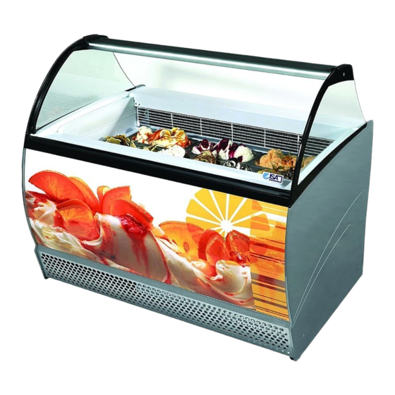
ISABELLA LX
06083 Bastia Umbra - Perugia - Italy
Tel. +39 075 80171 - Fax +39 075 8000900
EN
USE AND MAINTENANCE MANUAL
MODELS
10
RS TB
13
RS TB
ISA S.r.l.
Via del Lavoro, 5
www.isaitaly.com
ISABELLA LX
428000085137
1
R404A
Table of
Contents
Previous
Page
Next
Page
1
2
3
4
5
Advertisement
Table of Contents
Need help?
Do you have a question about the ISABELLA LX 10 and is the answer not in the manual?
Ask a question
Questions and answers
Related Manuals for ISA ISABELLA LX 10
Commercial Food Equipment ISA ISABELLA LX 13 Manual
(26 pages)
Commercial Food Equipment ISA MILLENIUM ST Use And Maintenance Manual
(60 pages)
Commercial Food Equipment ISA SuperCapri Series Use And Maintenance Manual
(212 pages)
Commercial Food Equipment ISA millennium 07 UL Operator's Manual
(82 pages)
Commercial Food Equipment ISA TORNADO 50 RV TB Use And Maintenance Manual
(32 pages)
Commercial Food Equipment ISA GALAXY TB H205 1P User Manual
(32 pages)
Commercial Food Equipment ISA millennium 07 Operator's Manual
(85 pages)
Commercial Food Equipment ISA Millennium 07 pas Operator's Manual
(66 pages)
Commercial Food Equipment ISA KALEIDO VP Use And Maintenance Manual
(32 pages)
Commercial Food Equipment ISA GELATOSUPERSHOW 2 Use And Maintenance Manual
(30 pages)
Commercial Food Equipment ISA GELATOSHOW 2 Use And Maintenance Manual
(36 pages)
Commercial Food Equipment ISA Stratos Series Use And Maintenance Manual
(212 pages)
Commercial Food Equipment ISA MY18 Manual
Reach dipping (20 pages)
Commercial Food Equipment ISA MITO POWER 12 Operator's Manual
(100 pages)
Commercial Food Equipment ISA VM Series Operator's Manual
(24 pages)
This manual is also suitable for:
Isabella lx 13
Table of Contents
Print
Rename the bookmark
Delete bookmark?
Delete from my manuals?
Login
Sign In
OR
Sign in with Facebook
Sign in with Google
Upload manual
Upload from disk
Upload from URL


Need help?
Do you have a question about the ISABELLA LX 10 and is the answer not in the manual?
Questions and answers