Advertisement
Quick Star t Guide
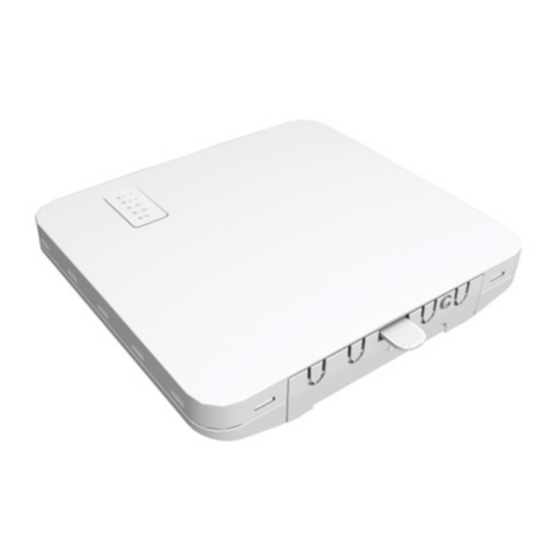
Cloud-Enabled Indoor/Outdoor Access Point
Spark™ AC Wave2, SP-W2-AC1200 with LTE Module
1. Unpack
a. Unpack the AP
◆
Spark SP-W2-AC1200
◆
Wall/Ceiling mounting bracket and
securing screw
◆
Wall-mount kit — 4 screws, 4 wall plugs
◆
Universal AC/DC power adapter
b. Unpack the LTE module
◆
LTE module for Spark SP-W2-AC1200
(external antenna kit or internal antenna
kit)
◆
USB cable
◆
Antennas — 2 external antennas
◆
Universal 12V/2A power adapter
2. Mount the AP
a. Mounting the AP on a Wall
1
1
1
At the installation location on the wall, use the wall/ceiling-
mount bracket to mark four holes for the wall plugs and
screws (included in wall-mount kit).
Drill four holes for the wall plugs, and then insert the plugs
and tap them flush with the wall surface.
Use the four screws to secure the bracket to the wall.
2
With its ports facing down, slide the AP down onto the
bracket until it snaps into its secured position.
Do not let go of the AP until you confirm that it is secure.
b. Mounting the AP on a Ceiling
2
1
1
Slide the wall/ceiling-mount bracket onto the rails on the
back of the AP until it snaps into its secured position.
2
Use the included screw to secure the bracket to the AP.
2
4
3
3
4
– 1 –
3
Press the retention clips of the wall/ceiling-mount bracket
against the ceiling T-bar.
4
Rotate the AP until the T-bar snaps into place.
Note:
The wall/ceiling-mount bracket supports two
different sizes of suspended ceiling T-bars. The position
illustrated above is for 15 mm bars. Use the position at a 90
degrees angle for 24.5 mm bars.
c. Mounting the AP on a Pole (requires optional pole-mount kit)
3
1
4
2
4
1
Attach the pole-mount bracket to the back of the AP.
2
Use the included screw to secure the bracket to the AP.
3
Feed the two steel-band clamps through the pole-mount
bracket mounting points.
4
Fasten the steel-band clamps around the pole to secure the
AP to the pole.
3. Connect Cables
a. Using the AC/DC Power Adapter
3
1
Connect the cable from the AC/DC power adapter to the DC
power jack on the AP.
Connect the power adapter to a nearby AC power source
(100-240 VAC, 50/60 Hz).
2
Connect Category 5e or better cable to the Eth0 RJ-45 port.
Connect the other end of this cable to a LAN switch.
3
(Optional) Connect local LAN devices to the other RJ-45 port
on the AP using Category 5e or better cable.
This 1000BASE-T port is labeled Eth1.
2
1
Spark SP-W2-AC1200
E092019-MR 150200001744X R04
Advertisement
Table of Contents

Related Manuals for Edge-Core Spark SP-W2-AC1200


Summary of Contents for Edge-Core Spark SP-W2-AC1200
- Page 1 24.5 mm bars. ◆ Universal AC/DC power adapter c. Mounting the AP on a Pole (requires optional pole-mount kit) b. Unpack the LTE module ◆ LTE module for Spark SP-W2-AC1200 (external antenna kit or internal antenna kit) ◆ USB cable ◆...
-
Page 2: Verify Ap Operation
If you select to manage the AP in stand-alone mode, use the web interface to manually make your configuration changes. During normal operation, the wireless LEDs should be on/ blinking green. For more information on AP configuration in stand-alone mode, please contact support team at ecwifi@edge-core.com – 2 –... - Page 3 Quick Start Guide 7. Install LTE Module d. Install the SIM card a. Remove protection Open the SIM card slot cover. Remove the EVA foam protection. Slide the SIM card into the slot until it clicks. b. Plug the USB e.
-
Page 4: Safety And Regulatory Information
Quick Start Guide Dynamic Frequency Selection (DFS) for devices operating in the bands 5250- 5350 MHz, 5470-5600 MHz and 5650-5725 MHz. Safety and Regulatory Information Sélection dynamique de fréquences (DFS) pour les dispositifs fonctionnant dans les bandes 5250-5350 MHz, 5470-5600 MHz et 5650- FCC Class B 5725 MHz. -
Page 5: Hardware Specifications
Quick Start Guide The full text of the EU declaration of conformity is available at the following internet address: Hardware Specifications www.ignitenet.com -> support. Chassis Japan Statement Size (L x W x H:) 176.72 x 162.44 x 32.5 mm (6.96 x 6.4 x 1.28 5 GHz band (W52, W53): Indoor use only in.) NCC Statement (Taiwan)
Need help?
Do you have a question about the Spark SP-W2-AC1200 and is the answer not in the manual?
Questions and answers