
Related Manuals for GYS ARCPULL 700


Summary of Contents for GYS ARCPULL 700
- Page 1 ARCPULL 700 02-31 / 92-100 32-61 / 92-100 62-91 / 92-100 73502 31/03/2022 Find user manuals in other languages www.gys.fr...
-
Page 2: Table Of Contents
Manuel d’utilisation ARCPULL 700 Notice originale Avertissements - Règles de sécurité ��������������������������������������������������������������������������������������������������������������������������� Description du matériel ����������������������������������������������������������������������������������������������������������������������������������������������������� Alimentation et mise en marche ������������������������������������������������������������������������������������������������������������������������������������ 3�1 Branchement sur groupe électrogène�������������������������������������������������������������������������������������������������������������������������������������9 3�2 Utilisation de rallonge ��������������������������������������������������������������������������������������������������������������������������������������������������������� 10 3�3 Connexion du pistolet au générateur������������������������������������������������������������������������������������������������������������������������������������ 10 3�4... -
Page 3: Avertissements - Règles De Sécurité
Manuel d’utilisation ARCPULL 700 Notice originale 1. AVERTISSEMENTS - RÈGLES DE SÉCURITÉ CONSIGNE GÉNÉRALE Ces instructions doivent être lues et bien comprises avant toute opération. Toute modification ou maintenance non indiquée dans le manuel ne doit pas être entreprise. Tout dommage corporel ou matériel dû à une utilisation non conforme aux instructions de ce manuel ne pourra être retenu à la charge du fabricant. - Page 4 Manuel d’utilisation ARCPULL 700 Notice originale Attention le soudage dans des milieux de petites dimensions nécessite une surveillance à distance de sécurité. Par ailleurs le soudage de certains matériaux contenant du plomb, cadmium, zinc ou mercure voire du béryllium peuvent être particulièrement nocifs, dégraisser également les pièces avant de les souder.
- Page 5 Manuel d’utilisation ARCPULL 700 Notice originale ÉMISSIONS ELECTRO-MAGNETIQUES Le courant électrique passant à travers n’importe quel conducteur produit des champs électriques et magnétiques (EMF) localisés. Le courant de soudage produit un champ électromagnétique autour du circuit de soudage et du matériel de soudage.
- Page 6 Manuel d’utilisation ARCPULL 700 Notice originale convient d’isoler l’opérateur de tels objets métalliques. e. Mise à la terre de la pièce à souder : Lorsque la pièce à souder n’est pas reliée à la terre pour la sécurité électrique ou en raison de ses dimensions et de son emplacement, ce qui est le cas, par exemple, des coques de navire ou des charpentes métalliques de bâtiments, une connexion...
-
Page 7: Description Du Matériel
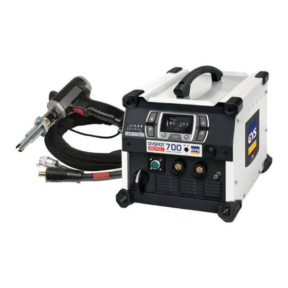
2. DESCRIPTION DU MATÉRIEL Le GYSPOT ARCPULL 700 est un poste à souder par arc tiré inverter triphasé qui permet de souder pièces rappor- tées (goujons, goujons à filetage interne, clous d’isolation, anneaux de tirage, tiges d’extraction de rivets, etc.) sur des matériaux à... - Page 8 Manuel d’utilisation ARCPULL 700 Notice originale Fig 2 : Vue extérieure du pistolet et son IHM (sans fourche de soudure ni accessoire) Gâchette Molette de verrouillage de la fourche de soudure Fûts (x2) d’insertion de la fourche de soudure Axe d’entrainement du porte-électrode Connecteur contrôle faisceau pistolet...
-
Page 9: Alimentation Et Mise En Marche
Manuel d’utilisation ARCPULL 700 Notice originale Porte-ancre à béton Support céramique Ø13 Ø13 068452 068322 3. ALIMENTATION ET MISE EN MARCHE Ce matériel peut être utilisé sur une installation électrique triphasée 400V ou 480V (50-60Hz) à quatre fils avec un neutre relié... -
Page 10: Utilisation De Rallonge
Manuel d’utilisation ARCPULL 700 Notice originale 3.2. UTILISATION DE RALLONGE Ce matériel peut être raccordé à l’installation électrique au moyen d’une rallonge à condition qu’elle réponde aux exigences suivantes : - Rallonge à 4 fils avec conducteur de terre - La longueur ne doit pas dépasser 10m - La section des conducteurs ne doit pas être inférieure à... -
Page 11: Modèle De Goujon Et Protection Du Bain De Surface
Manuel d’utilisation ARCPULL 700 Notice originale L’amorçage : la pièce rapportée (anneau de tirage, goujons, etc.) est mise en contact avec la tôle support. Un appui sur la gâchette démarre le processus de soudage : le générateur envoie du courant dans le goujon, l’axe du pistolet se lève légèrement, un arc électrique de faible intensité... -
Page 12: Protection Du Bain De Fusion
Manuel d’utilisation ARCPULL 700 Notice originale 5.3. PROTECTION DU BAIN DE FUSION En fonction du matériau à souder, une protection du bain de fusion par férule en céramique ou par protection gazeuse peut-être nécessaire. Le tableau ci-dessous liste le gaz qu’il est recommandé d’utiliser en fonction de la pièce à souder et de son matériau. -
Page 13: Polarité Du Pistolet
Dépendant du type de pièce à souder, et de sa matière, il est préférable de connecter la texas positive du pistolet à la borne + ou – du générateur. Ci-dessous le tableau du choix de polarité retenu par GYS. Pièce rapportée à souder... -
Page 14: Positionnement Des Pinces De Masse Et Soufflage D'arc
Manuel d’utilisation ARCPULL 700 Notice originale Goujon acier bas carbone M6 sans gaz sur épaisseur 26/min 26/min de 4 mm Goujon acier bas carbone M8 sans gaz sur épaisseur 24/min 21/min de 4 mm Ancre à béton acier bas carbone Ø10 mm avec férule 14/min céramique sur épaisseur 6 mm... -
Page 15: Choix De L'adaptateur Férule Céramique
Manuel d’utilisation ARCPULL 700 Notice originale 6.1. CHOIX DE L’ADAPTATEUR FÉRULE CÉRAMIQUE Choisir la férule céramique adaptée à la pièce rapportée à souder (type, diamètre). Rappel de la norme ISO 13918 sur le choix des férules en fonction des types de pièces à souder Type de pièces rapportées... -
Page 16: Installation Accessoires Et Réglage Du Pistolet
Manuel d’utilisation ARCPULL 700 Notice originale 7. INSTALLATION ACCESSOIRES ET RÉGLAGE DU PISTOLET La mise en place des accessoires et leur réglage sur le pistolet doivent impérativement se faire : - pistolet connecté au générateur - produit mis sous tension Appui gachette - phase d’initialisation du pistolet terminée (demande d’appui gâchette) -
Page 17: Utilisation Accessoire Pour Pose D'anneaux De Tirage Du Kit Arcpull Rivet Box 700
Manuel d’utilisation ARCPULL 700 Notice originale Si soudure sous protection gazeuse : raccorder le tuyau de gaz de la fourche au connecteur du pistolet. Note : Le vissage des pièces doit se faire au moyen de clé plate. L’utilisation de pince multiprise est à proscrire. -
Page 18: 7�3 Utilisation Accessoire Pour Pose De Tige D'extraction De Rivet Du Kit Arcpull Rivet Box 700
Manuel d’utilisation ARCPULL 700 Notice originale 7.3. UTILISATION ACCESSOIRE POUR POSE DE TIGE D’EXTRACTION DE RIVETS DU KIT ARCPULL RIVET BOX 700 Insérer la tige inox d’extraction de rivets dans le porte-goujon et régler la vis du porte-goujon pour garantir qu’il sorte de 13.5 à... -
Page 19: Manipulation Du Pistolet
Manuel d’utilisation ARCPULL 700 Notice originale 8. MANIPULATION DU PISTOLET 8.1. SOUDURE DES ANNEAUX DE TIRAGE 1. Monter l’accessoire de pose d’anneau de tirage du kit ArcPull Rivet box 700 (voir §7.2). 2. Positionner les pinces de masse sur la tôle support en faisant en sorte qu’il y ait équidistance entre les pinces et la zone de soudure de l’anneau (voir §5.7). -
Page 20: Mode De Fonctionnement Du Produit
Manuel d’utilisation ARCPULL 700 Notice originale 9. MODE DE FONCTIONNEMENT DU PRODUIT Fig 3 : Vue du clavier du générateur Écran Bouton G+ Bouton G- Bouton D+ Bouton D- Bouton Menu Principal/Valider Bouton Retour/Annuler Le produit dispose de mode de fonctionnement synergique et manuel, ainsi que d’un moyen pour sauvegarder et rappeler des configurations de soudure. -
Page 21: 9�1�1 Type De Pièces À Souder
Ces synergies restent valables pour des pièces rapportées plus longues (jusqu’ à 100mm) tant qu’elles sont du même type et du même matériau que celles vendues par GYS (selon l’ISO 13918). Les synergies des pièces rapportées en aluminium (hors anneaux de tirage), ont été établies sur des tôles supports préchauffées à... -
Page 22: 9�2�2 Épaisseur De La Tôle Support
Manuel d’utilisation ARCPULL 700 Notice originale Clou d’isolation Plot de masse La valeur Mx correspond au filetage du vissage. 9.1.2. ÉPAISSEUR DE LA TÔLE SUPPORT Épaisseur affichée en millimètre. Pour augmenter ou diminuer l’épaisseur de la tôle sur laquelle la pièce rapportée sera soudée, appuyer sur les touches D+ et D-. -
Page 23: Liste Des Messages Affichés En Bas De L'écran De Soudage
Manuel d’utilisation ARCPULL 700 Notice originale Pour augmenter ou diminuer la durée d’arc (valeur ), appuyer sur les touches G+ et G-. Pour augmenter ou diminuer le courant d’arc (valeur ), appuyer sur les touches D+ et D-. Pour modifier les autres paramètres de soudage manuel (courant et temps des étapes de soudage), se reporter au chapitre «... -
Page 24: 9�4�1 Menu Réglage En Mode Synergique
Manuel d’utilisation ARCPULL 700 Notice originale 9.4.1. MENU RÉGLAGE EN MODE SYNERGIQUE Lorsque le poste fonctionne en mode synergique, le menu de réglages permet de sélectionner le type de pièce rap- portée à souder, sa taille, son matériau et son type de protection gazeuse. -
Page 25: 9�4�3 Menu Programmes
Manuel d’utilisation ARCPULL 700 Notice originale 2 - Amorçage : • Réglable de -2 à +8. Joue directement sur la consigne du convertisseur de puissance du poste. • À 0 (valeur par défaut), le produit assure un amorçage optimal sans risque de rupture d’arc lors de la levée de la pièce rapportée tout en limitant le courant de court-circuit. -
Page 26: 9�4�4 Menu Configuration
Manuel d’utilisation ARCPULL 700 Notice originale 9.4.4. MENU CONFIGURATION Configuration > Pregaz > 400ms Postgaz 400ms Langue Reset machine Info Appuyer sur les touches G+ et G- pour les déplacer le curseur de gauche (Pré-gaz, Post-gaz, Langue, Reset ma- chine, Info.). -
Page 27: Pilotage Par Automate Connect
Manuel d’utilisation ARCPULL 700 Notice originale 9.4.4.2. Panneau d’informations Info machine Soft gene V3.0 Hard gene V1.0 Pistolet Soft pistolet V3.0 Hard pistolet V7.0 Le panneau d’information précise les numéros des versions logicielles et hardward du générateur et, si le pistolet est connecté, son type (200-350, 700). -
Page 28: Caractéristiques Techniques Des Entrées/Sorties Et Alimentation
Manuel d’utilisation ARCPULL 700 Notice originale 10.2. CARACTÉRISTIQUES TECHNIQUES DES ENTRÉES/SORTIES ET ALIMENTATION Alimentation : fournir une alimentation +24V 1.6 A max Entrées : consommation max de 10 mA par entrée Sorties : courant max 100 mA Isolation diélectrique : 2 kVAC 50/60 Hz pour 1minute... -
Page 29: Chronogrammes
Manuel d’utilisation ARCPULL 700 Notice originale 10.3. CHRONOGRAMMES 10.3.1. INITIALISATION À LA MISE SOUS TENSION Lorsqu’il est piloté par automate, l’initialisation du produit nécessite: - qu’aucune pièce rapportée ne soit montée sur le pistolet - aucune contrainte mécanique ne doit être appliquée sur l’axe d’entrainement du porte-électrode du pistolet L’activation du pilotage par automate peut se faire avant ou après la mise sous tension du produit. -
Page 30: 10�3�2 Cycle De Soudage
Manuel d’utilisation ARCPULL 700 Notice originale 10.3.2. CYCLE DE SOUDAGE ACTIVE 24 V CONNECT 24 V READY durée ≥ Prégaz 24 V CONTACT 24 V TRIGGER durée ≥ Postgaz 24 V ARC_ON robot en mouvement robot en position sur le point de soudage... -
Page 31: Message D'erreur, Anomalies, Causes, Remèdes
Manuel d’utilisation ARCPULL 700 Notice originale 11. MESSAGE D’ERREUR, ANOMALIES, CAUSES, REMÈDES Ce matériel dispose d’un système de contrôle de défaillance. En cas de défaillance, des messages d’erreur peuvent s’afficher. Message d’erreur Signification Causes Remèdes Protection thermique du Dépassement du facteur de Attendre l’extinction du message... - Page 32 Operating manual Translation of the original ARCPULL 700 instructions Warnings - Safety Rules ������������������������������������������������������������������������������������������������������������������������������������������������� Product Description ��������������������������������������������������������������������������������������������������������������������������������������������������������� Power Supply and Starting the Machine ����������������������������������������������������������������������������������������������������������������� 3�1 Plugging In the Machine ����������������������������������������������������������������������������������������������������������������������������������������������������� 39 3�2 Using Extension Cables ������������������������������������������������������������������������������������������������������������������������������������������������������� 40 3�3 Connecting the Gun to the Machine ������������������������������������������������������������������������������������������������������������������������������������� 40 3�4...
-
Page 33: Warnings - Safety Rules
Operating manual Translation of the original ARCPULL 700 instructions 1. WARNINGS - SAFETY REGULATIONS GENERAL INFORMATION These instructions must be fully read and understood before operating the machine. Do not carry out any modifications or maintenance work that is not included in the user manual. - Page 34 Operating manual Translation of the original ARCPULL 700 instructions Caution: Welding in confined environments requires remote monitoring for safety reasons. Furthermore, welding certain materials that contain lead, cadmium, zinc, mercury or even beryllium, can be particularly harmful; it is important to thoroughly degrease the parts before welding them.
- Page 35 Operating manual Translation of the original ARCPULL 700 instructions ELECTROMAGNETIC EMISSIONS An electric current passing through any conductor produces localised electric and magnetic fields (EMF). The welding current produces an electromagnetic field around the welding circuit and the welding equipment.
- Page 36 Operating manual Translation of the original ARCPULL 700 instructions e. Earthing the workpiece: Where the part to be welded is not earthed for electrical safety reasons or because of its size and location, e.g. a ship’s hulls or a building’s structural steel framework, an earthed connection can, in some cases but not always, reduce emissions. Care should be taken to avoid earthing parts which could increase the risk of injury to users or damage to other electrical equipment.
-
Page 37: Product Description
2. EQUIPMENT DESCRIPTION The GYSPOT ARCPULL 700 is a three-phase, inverter arc welder for welding consumables and fittings, including threaded studs, internally threaded studs, insulation nails, pulling rings and rivet extraction rods, etc.) on aluminium- and steel-based materials. It offers both a SYNERGY and MANUAL operating mode. The program menu allows you to store and recall welding configurations. - Page 38 Operating manual Translation of the original ARCPULL 700 instructions Trigger Welding fork locking mechanism Welding fork insertion barrels (x2) Electrode holder drive shaft Gun control cable connection Positive dinse Gas-outlet connection Gas-inlet connection Ready LED (green) Contact LED (blue) Fault LED (red)
-
Page 39: Power Supply And Starting The Machine
Operating manual Translation of the original ARCPULL 700 instructions Stud support (Ø 13) Ceramic support Ø13 068452 068322 3. POWER SUPPLY AND STARTING THE MACHINE This equipment can be used on a three-phase, 400 or 480 V (50 - 60 Hz), four-wire electrical system with an earthed neutral. -
Page 40: Using Extension Cables
Operating manual Translation of the original ARCPULL 700 instructions 3.2. USING EXTENSION CABLES This equipment may be connected to the electrical system using an extension cable provided that it meets the fol- lowing requirements: - It must be a four-wire extension cable with an earthed conductor. -
Page 41: Threaded Stud Type And Weld Pool Protection
Operating manual Translation of the original ARCPULL 700 instructions Ignition: the consumable (pulling ring or threaded studs, etc.) is brought into contact with the support sheet. Pressing the trigger will start the welding process: the power source sends a current to the threaded stud, the gun raises the threaded stud slightly and a low-intensity electric arc is created. -
Page 42: Protecting The Weld Pool
Operating manual Translation of the original ARCPULL 700 instructions 5.3. PROTECTING THE WELD POOL Depending on the material to be welded, it may be necessary to protect the weld pool with a ceramic ferrule or gas shield. The table below lists the recommended gas to use depending on the workpiece and its material. These gases make the weld stronger and correspond to the gas used when the machine is operating in SYNERGY mode (see §9.1). -
Page 43: The Gun's Polarity
The machine’s welding rate is calculated continuously in accordance with IEC 60974-9. Depending on the type of gun used (the ARCPULL 200-350 or the ARCPULL 700 and above), the current and the welding time, the machine will take more or less time to rest between two welds. -
Page 44: 5�7 Positioning The Earthing Clamps And Arc Extinction
Operating manual Translation of the original ARCPULL 700 instructions Low-carbon, steel threaded stud without gas shielding 26/min 26/min on a sheet thickness of 4 mm Low-carbon, steel threaded stud without gas shielding 24/min 21/min on a sheet thickness of 4 mm Low-carbon steel stud support (Ø10 mm) with ceramic... -
Page 45: 6�1 Choosing A Ceramic Ferrule Adaptor
Operating manual Translation of the original ARCPULL 700 instructions 6.1. SELECTING A CERAMIC FERRULE ADAPTOR Choosing the right ceramic ferrule for the consumable to be welded (type and diameter). Standard ISO 13918 states that the choice of ferrules depends on the type of parts to be welded. -
Page 46: Setting Up The Accessories And Adjusting The Gun
Operating manual Translation of the original ARCPULL 700 instructions 7. SETTING UP ACCESSORIES AND ADJUSTING THE GUN Fitting and adjusting the accessories on the gun must be done in the fol- lowing way: - make sure the gun is connected to the power source... -
Page 47: 7�2 Which Accessory To Use To Position Arcpull Rivet Box 700 Pulling Rings
Operating manual Translation of the original ARCPULL 700 instructions If welding under gas shielding: Connect the gas hose from the fork to the gun connection. Note: The parts must be screwed on using a spanner. Using pliers is not recommended. -
Page 48: 7�3 Which Accessory To Use To Set Up Arcpull Rivet Box 700 Rivet-Extraction Rods
Operating manual Translation of the original ARCPULL 700 instructions 7.3. USING ACCESSORIES TO PLACE ARCPULL RIVET BOX 700 RIVET-EXTRACTION RODS Insert the stainless steel, rivet-extrac- tion rod into the stud holder and adjust the stud holder screw to ensure that it extends 13.5 - 15 mm from the stud... -
Page 49: Handling The Gun
Operating manual Translation of the original ARCPULL 700 instructions 8. OPERATING THE GUN 8.1. WELDING PULLING RINGS 1. Fit the pulling ring consumable from the ArcPull rivet box 700 kit (see section 7.2). 2. Position the earthing clamps on the support sheet so that there is an equal distance between the clamps and the ring’s welding area (see §5.7). -
Page 50: How The Device Works
When the ARCPULL 700 is switched on, it will return to the operating mode it was in when it was last switched off. Changing the mode (between MANUAL and SYNERGY mode) and recalling welding configurations is done via the device’s main menu. -
Page 51: 9�1�1 Which Parts Can Be Welded
These synergies are also suitable for longer consumables (up to 100 mm) as long as they are of the same type and material as those sold by GYS (according to ISO 13918). The synergies for aluminium consumables (excluding pulling rings) have been established for welding support sheets preheated to a temperature of 50 - 60°C. -
Page 52: 9�2�2 Support Sheet Thickness
Operating manual Translation of the original ARCPULL 700 instructions Insulation nail Earthing chuck The Mx value corresponds to the screw’s thread. 9.1.2. SUPPORT SHEET THICKNESS Thickness in millimetres. To increase or decrease the thickness of the sheet to which the part will be welded, press the D+ and D- keys. -
Page 53: List Of Messages Displayed At The Bottom Of The Welding Screen
Operating manual Translation of the original ARCPULL 700 instructions To increase or decrease the arc time ( value), press the G+ and G- keys. To increase or decrease the arc current ( value), press the D+ and D- keys. To change the other manual welding settings (current and welding-phase times), see the chapter entitled ‘Manual Settings’. -
Page 54: 9�4�1 Synergy Mode Setup Menu
Operating manual Translation of the original ARCPULL 700 instructions 9.4.1. SYNERGY MODE SETTINGS MENU When the unit is in SYNERGY mode, the settings menu allows the user to select the type of consumable, its size, material and gas-shielding method. In SYNERGY mode, the settings are selected in the following order: 1 - ‘Electrode’... -
Page 55: 9�4�3 Menu Programs
Operating manual Translation of the original ARCPULL 700 instructions 2 - Ingition: • Adjustable from -2 to +8. Directly affects the setpoint of the device’s power converter. • When set to 0 (the default value), the equipment achieves optimal ignition without the risk of arc breakage when the consumable is lifted, whilst also limiting the short-circuit current. -
Page 56: 9�4�4 Configuring The Menu
Resetting the ArcPull 700 will clear all the welding settings from the program menu, switching the pro- duct back to French will return the Pre-Gas and Post-Gas phases to 0.4 s. -
Page 57: Controlling The Device Via A Plc
10. CONTROLLING THE DEVICE VIA A PLC The ArcPull 700 has a rear panel connection for PLC control. The welding settings must be set from the product’s HMI. When the product is controlled by a PLC, ‘Connect’ is displayed on the screen. In CONNECT mode, pressing the trigger no longer affects the gun. -
Page 58: 10�2 Input/Output And Power Supply Technical Specifications
Operating manual Translation of the original ARCPULL 700 instructions 10.2. INPUT/OUTPUT AND POWER SUPPLY TECHNICAL DATA Power supply: +24 V / 1.6 A max. power supply Inputs: max. power consumption 10 mA per input Outputs: max. current 100 mA Dielectric insulation: 2 kVAC 50/60 Hz for one minute... -
Page 59: Timeline
Operating manual Translation of the original ARCPULL 700 instructions 10.3. TIMELINE 10.3.1. POWER-UP INITIALISATION When it is controlled by a PLC, the product’s start-up requires that: - no consumables are fitted to the gun - no mechanical stress should be exerted on the gun’s electrode holder drive shaft The PLC can be activated before or after the product is switched on. -
Page 60: 10�3�2 Welding Cycles
Operating manual Translation of the original ARCPULL 700 instructions 10.3.2. WELDING CYCLE ACTIVE 24 V CONNECT 24 V READY duration ≥ Pre-Gas 24 V CONTACT 24 V TRIGGER duration ≥ Post-Gas 24 V ARC_ON machine in motion machine in position... -
Page 61: Gun
Operating manual Translation of the original ARCPULL 700 instructions 11. ERROR MESSAGE, FAULTS, CAUSES, SOLUTIONS This equipment has a fault monitoring system. In the event of a fault, error messages may be displayed. Error message Meaning Causes Solutions The power source’s ther- Exceeding the duty cycle. - Page 62 Betriebsanleitung Übersetzung der ARCPULL 700 Originalbetriebsanleitung Warnungen - Sicherheitsregeln ���������������������������������������������������������������������������������������������������������������������������������� Beschreibung des Geräts ����������������������������������������������������������������������������������������������������������������������������������������������� Versorgung und Inbetriebnahme ������������������������������������������������������������������������������������������������������������������������������� 3�1 Anschluss an einen Generator ��������������������������������������������������������������������������������������������������������������������������������������������� 69 3�2 Verwendung eines Verlängerungskabels ������������������������������������������������������������������������������������������������������������������������������� 70 3�3 Anschluss der Pistole an den Generator�������������������������������������������������������������������������������������������������������������������������������� 70 3�4 Aktualisierung des Geräts����������������������������������������������������������������������������������������������������������������������������������������������������...
-
Page 63: Warnungen - Sicherheitsregeln
Betriebsanleitung Übersetzung der ARCPULL 700 Originalbetriebsanleitung 1. WARNUNGEN - SICHERHEITSREGELN ALLGEMEINER HINWEIS Die Missachtung dieser Bedienungsanleitung kann zu schweren Personen- und Sachschäden führen. Nehmen Sie keine Wartungsarbeiten oder Veränderungen an dem Gerät vor, die nicht in der Anlei- tung genannt werden. - Page 64 Betriebsanleitung Übersetzung der ARCPULL 700 Originalbetriebsanleitung SCHWEISSRAUCH/-GAS Beim Schweißen entstehen Rauchgase bzw. toxische Dämpfe. Es muss für eine ausreichende Belüftung gesorgt werden, und manchmal ist eine Luftzufuhr erforderlich. Eine Frischluftmaske kann bei unzureichender Belüftung eine Lösung sein. Überprüfen Sie die Wirksamkeit der Luftansaugung, indem Sie diese anhand der Sicherheitsnormen überprüfen.
- Page 65 Betriebsanleitung Übersetzung der ARCPULL 700 Originalbetriebsanleitung Unter der Voraussetzung, dass die Impedanz des öffentlichen Niederspannungsnetzes am gemeinsamen Koppelpunkt kleiner als Zmax = 0,36 Ohm ist, entspricht dieses Gerät der Norm IEC 61000-3-11 und kann an öffentliche Niederspannungsnetze angeschlossen werden. Der Installateur oder Nutzers des Geräts ist zuständig dafür, dass die Netzimpedanz den Impedanzbeschränkungen entspricht, wobei er ggf.
- Page 66 - Legen Sie Schweißbrenner oder Elektrodenhalter immer auf einer isolierten Fläche ab, wenn sie nicht benutzt werden! Die Versorgungs-, Verlängerungs- und Schweißkabel müssen komplett abgerollt werden, um ein Überhitzen zu verhindern. Der Hersteller GYS haftet nicht für Verletzungen oder Schäden, die durch unsachgemäße Handhabung dieses Gerätes entstanden sind.
-
Page 67: Beschreibung Des Geräts
Originalbetriebsanleitung 2. BESCHREIBUNG DES GERÄTS GYSPOT ARCPULL 700 ist ein dreiphasiges Inverter-Schweißgerät mit Hubzündung zum Schweißen von Aufsatz- stücken (Stifte, Stifte mit Innengewinde, Isolationsnägel, Zugringe, Nietenausziehstifte usw.) an Materialien auf Aluminium- oder Stahlbasis. Es verfügt über einen synergetischen und einen manuellen Betriebsmodus. Das Menü... - Page 68 Betriebsanleitung Übersetzung der ARCPULL 700 Originalbetriebsanleitung Abb. 2: Außenansicht der Pistole und ihres HMI (ohne Schweißgabel oder Zubehör) Brennertaster Feststellknopf der Schweißgabel Hülsen (x2) zum Einsetzen der Schweißgabel Antriebsachse des Elektrodenhalters Steueranschluss Pistolen-Kabelschlauchpaket Texasbuchse positiv Gasanschluss Ausgang Gasanschluss Eingang LED bereit (grün)
-
Page 69: Versorgung Und Inbetriebnahme
Betriebsanleitung Übersetzung der ARCPULL 700 Originalbetriebsanleitung Beton-Ankerhalter Keramik-Suppot Ø13 Ø13 068452 068322 3. VERSORGUNG UND INBETRIEBNAHME Dieses Gerät kann in einer dreiphasigen 400 V oder 480 V (50-60 Hz) elektrischen Installation mit vier Leitungen und ei- nem geerdeten Neutralleiter verwendet werden. Es wird mit einem 32 A-Stecker des Typs EN60309-1 geliefert und muss in diesem Fall an einem 400 V-Netz betrieben werden. -
Page 70: Verwendung Eines Verlängerungskabels
Betriebsanleitung Übersetzung der ARCPULL 700 Originalbetriebsanleitung 3.2. VERWENDUNG EINES VERLÄNGERUNGSKABELS Dieses Gerät kann mit einem Verlängerungskabel an die elektrische Anlage angeschlossen werden, sofern es die folgenden Anforderungen erfüllt: - 4-adriges Verlängerungskabel mit Erdungsleiter - Die Länge darf 10 m nicht überschreiten - Der Querschnitt der Leiter darf nicht kleiner als 4 mm²... -
Page 71: Stiftmodell Und Schutz Des Oberflächenbades
Betriebsanleitung Übersetzung der ARCPULL 700 Originalbetriebsanleitung Zündung: Das Aufsatzstück (Zugring, Stifte usw.) wird mit dem Trägerblech in Kontakt gebracht. Ein Druck auf den Brennertaster startet den Schweißvorgang: Die Stromquelle schickt Strom an den Stift, die Pistolenachse steigt leicht an, es entsteht ein Lichtbogen mit geringer Stärke. -
Page 72: Schutz Des Schmelzbads
Betriebsanleitung Übersetzung der ARCPULL 700 Originalbetriebsanleitung 5.3. SCHUTZ DES SCHMELZBADS Je nach dem zu schweißenden Material kann ein Schutz des Schmelzbades durch eine Keramikhülse oder durch Schutzgas erforderlich sein. In der folgenden Tabelle sind die Schutzgase aufgelistet, die je nach den zu schweißenden Stücken und deren Mate- rial verwendet werden sollten. -
Page 73: Polarität Der Pistole
Die Polarität der Pistole wirkt sich auf die Qualität der Schweißstelle aus. Abhängig von der Art des zu schweißenden Teils und seinem Material ist es vorzuziehen, den Pluspol der Pistole mit dem Plus- oder Minuspol des Generators zu verbinden. Nachfolgend die Tabelle der von GYS gewählten Polaritätswahl Zu schweißendes Aufsatzstück... -
Page 74: Positionierung Der Masseklemmen Und Des Lichtbogenschachts
Betriebsanleitung Übersetzung der ARCPULL 700 Originalbetriebsanleitung Stift aus kohlenstoffarmem Stahl M6 gasfrei auf 4 mm Dicke 26/min 26/min Stift aus kohlenstoffarmem Stahl M8 gasfrei auf 4 mm Dicke 24/min 21/min Betonanker aus kohlenstoffarmem Stahl Ø10 mm mit Kera- 14/min mikhülse auf 6 mm Dicke Betonanker Ø13 mm mit Keramik auf Dicke 10 mm... -
Page 75: Auswahl Des Keramik-Hülsenadapters
Betriebsanleitung Übersetzung der ARCPULL 700 Originalbetriebsanleitung 6.1. AUSWAHL DES KERAMIK-HÜLSENADAPTERS Wählen Sie die richtige Keramikhülse für das zu schweißende Aufsatzstück (Typ, Durchmesser). Erinnerung an die Norm ISO 13918 zur Auswahl von Hülsen je nach Art der zu schweißenden Stücke Typ der Aufsatzstücke Bezeichnung der Hülse nach ISO... -
Page 76: Installation Von Zubehör Und Einstellung Der Pistole
Betriebsanleitung Übersetzung der ARCPULL 700 Originalbetriebsanleitung 7. INSTALLATION VON ZUBEHÖR UND EINSTELLUNG DER PISTOLE Das Anbringen von Zubehörteilen und deren Einstellung an der Pistole muss unbedingt wie folgt erfolgen: - Pistole an der Stromquelle angeschlossen - Gerät unter Spannung - Initialisierungsphase der Pistole abgeschlossen (Aufforderung zum Ab- Ausloser Drucken drücken der Brennertaste) -
Page 77: 7,2. Zubehör Zur Installation Von Zugringen Aus Dem Arcpull Rivet Box 700 Kit
Betriebsanleitung Übersetzung der ARCPULL 700 Originalbetriebsanleitung Wenn das Schweißen unter Schutzgas erfolgt: Schließen Sie den Gasschlauch der Gabel an den Anschluss der Pistole an. Hinweis: Das Verschrauben der Stücke sollte mit einem Schraubenschlüssel erfolgen. Es dürfen keine Rohrzangen benutzt werden. -
Page 78: Zubehör Zur Installation Des Nietenausziehstifts Des Arcpull Rivet Box 700 Kits
Betriebsanleitung Übersetzung der ARCPULL 700 Originalbetriebsanleitung 7.3. ZUBEHÖR ZUR INSTALLATION DES NIETENAUSZIEHSTIFTS DES ARCPULL RIVET BOX 700 KITS Führen Sie den Edelstahl-Nietenaus- ziehstift in den Stifthalter ein und stellen Sie die Schraube des Stifthalters so ein, dass gewährleistet ist, dass er 13,5 bis 15 mm aus dem Stifthalter herausragt. -
Page 79: Manipulation Der Pistole
Betriebsanleitung Übersetzung der ARCPULL 700 Originalbetriebsanleitung 8. MANIPULATION DER PISTOLE 8.1. SCHWEISSEN VON ZUGRINGEN 1. Montieren Sie das Zubehör für den Zugring aus dem ArcPull Rivet box 700 Kit (siehe §7.2). 2. Positionieren Sie die Masseklemmen auf dem Trägerblech, wobei der Abstand zwischen den Klemmen und dem Schweißbereich des Rings gleich groß... -
Page 80: Funktionsweise Des Geräts
Betriebsanleitung Übersetzung der ARCPULL 700 Originalbetriebsanleitung 9. FUNKTIONSWEISE DES GERÄTS Abb. 3: Ansicht der Tastatur der Stromquelle Bildschirm Taste G+ Taste G- Taste D+ Taste D- Taste Hauptmenü/Bestätigen Taste Zurück/Löschen Verfügt über einen synergetischen und einen manuellen Betriebsmodus sowie eine Möglichkeit, Schweißkonfiguratio- nen zu speichern und abzurufen. -
Page 81: 9�1�1 Art Der Zu Schweißenden Stücke
Diese Synergien bleiben für längere Aufsatzstücke (bis 100mm) gültig, solange sie vom gleichen Typ und aus dem gleichen Material sind wie die von GYS verkauften Aufsatzstücke (nach ISO 13918). Die Synergien der Aluminium-Aufsatzstücke (ohne Zugringe), wurden auf vorgewärmten Trägerblechen bei einer Tem- peratur von 50-60 °C ermittelt. -
Page 82: 9�2�2 Stärke Des Trägerblechs
Betriebsanleitung Übersetzung der ARCPULL 700 Originalbetriebsanleitung Isoliernagel Massestift Der Mx-Wert entspricht dem Schraubengewinde. 9.1.2. DICKE DES TRÄGERBLECHS Angezeigte Stärke in Millimetern. Um die Stärke des Blechs, auf das das Aufsatzstück geschweißt wird, zu erhöhen oder zu verringern, drücken Sie die Tasten D+ und D-. -
Page 83: Liste Der Meldungen, Die Am Unteren Rand Des Schweißbildschirms Angezeigt Werden
Betriebsanleitung Übersetzung der ARCPULL 700 Originalbetriebsanleitung Um die Lichtbogendauer (Wert ) zu erhöhen oder zu verringern, drücken Sie die Tasten G+ und G-. Um den Strom des Lichtbogens (Wert ) zu erhöhen oder zu verringern, drücken Sie die Tasten D+ und D-. -
Page 84: 9�4�1 Einstellmenü Im Synergie-Modus
Betriebsanleitung Übersetzung der ARCPULL 700 Originalbetriebsanleitung 9.4.1. EINSTELLMENÜ IM SYNERGIE-MODUS Wenn das Gerät im Synergie-Modus arbeitet, können Sie im Menü Einstellungen den Typ des zu schweißenden Auf- satzstücks, seine Größe, sein Material und die Art des Schutzgases auswählen. Im Synergie-Modus werden die Einstellungen in der Reihenfolge von oben nach unten gewählt: 1 - Einsatztyp „Elektrode“: Stift, Nagel, Ring usw. -
Page 85: 9�4�3 Menü Programme
Betriebsanleitung Übersetzung der ARCPULL 700 Originalbetriebsanleitung 2 - Zündung: • Einstellbar von -2 bis +8. Verwendet direkt den Sollwert des Stromwandlers des Geräts. • Bei 0 (Standardeinstellung) gewährleistet das Gerät eine optimale Zündung ohne die Gefahr eines Lichtbogenbruchs beim Anheben des Aufsatzstücks und begrenzt gleichzeitig den Kurzschlussstrom. -
Page 86: 9�4�4 Menü Konfiguration
Betriebsanleitung Übersetzung der ARCPULL 700 Originalbetriebsanleitung 9.4.4. MENÜ KONFIGURATION Konfiguration > Pregas > 400ms Postgas 400ms Sprache Reset Maschine Info Drücken Sie die Tasten G+ und G-, um den linken Cursor zu bewegen (Gasvorströmung, Gasnachströmung, Sprache, Gerät zurücksetzen, Info.). Wenn die Punkte Gasvorströmung, Gasnachströmung oder Sprache markiert sind, drücken Sie die Tasten D+ und D-, um den Wert zu ändern. -
Page 87: Steuerung Durch Sps Connect
Betriebsanleitung Übersetzung der ARCPULL 700 Originalbetriebsanleitung 9.4.4.2. Informationsfeld Info Soft gene V3.0 Hard gene V1.0 Pistole Soft Pistole V3.0 Hard Pistole V7.0 Das Informationsfeld gibt die Nummern der Software- und Hardwareversionen der Stromquelle und der Pistole, falls angeschlossen, und den Typ an. -
Page 88: Technische Eigenschaften Der Ein-/Ausgänge Und Stromversorgung
Betriebsanleitung Übersetzung der ARCPULL 700 Originalbetriebsanleitung 10.2. TECHNISCHE EIGENSCHAFTEN DER EIN-/AUSGÄNGE UND STROMVERSORGUNG Versorgung: Bereitstellung einer Versorgung von +24 V 1,6 A max Eingänge: max. Verbrauch von 10 mA pro Eingang Ausgänge: max. Strom 100 mA Dielektrische Isolierung: 2 kV-AC 50/60 Hz für 1 Minute... -
Page 89: Chronogramme
Betriebsanleitung Übersetzung der ARCPULL 700 Originalbetriebsanleitung 10,3. CHRONOGRAMME 10.3.1. INITIALISIERUNG BEIM EINSCHALTEN Wenn das Gerät durch eine SPS gesteuert wird, erfordert die Initialisierung Folgendes: - dass keine Aufsatzstücke an der Pistole angebracht sind - dass auf die Antriebsachse des Elektrodenhalters der Pistole keine mechanische Belastung ausgeübt werden darf. -
Page 90: 10�3�2 Schweißzyklus
Betriebsanleitung Übersetzung der ARCPULL 700 Originalbetriebsanleitung 10.3.2. SCHWEISSZYKLUS ACTIVE 24 V CONNECT 24 V READY dauer ≥ Pregaz 24 V CONTACT 24 V TRIGGER dauer ≥ Postgas 24 V ARC_ON bewegter Roboter Roboter in Position auf der Schweißstelle bewegter Roboter Roboter in Schweißposition... -
Page 91: Error Messages, Faults, Causes And Solutions
Betriebsanleitung Übersetzung der ARCPULL 700 Originalbetriebsanleitung 11. FEHLERMELDUNGEN, ANOMALIEN, URSACHEN, LÖSUNGEN Dieses Gerät verfügt über ein Fehlerkontrollsystem. Bei einem Fehler können Fehlermeldungen angezeigt werden. Fehlermeldung Bedeutung Ursache Abhilfemaßnahmen Wärmeschutz der Einschaltdauer ist über- Warten, bis Nachricht erlischt, um weiter Stromquelle schritten. -
Page 92: Schéma Électrique Et Pièces De Rechange
Schéma électrique ARCPULL 700 ELECTRICAL DIAGRAM / STROMLAUFPLAN... - Page 93 Pièces de rechange ARCPULL 700 REPLACEMENT PARTS / ERSATZTEILE Patin de protection haut / High protection pad / Oberes Schutzpolster 56163 Poignée / Handle / Griff 56014 Protection écran / Screen protector / Bildschirmschutz 56175 Ecran / Display screen / Bildschirm 51992 Support plastique / Plastic support / Kunststoffträger...
- Page 94 Ventilateur 120x120x38 / Fan (120 x 120 x 38) / Lüfter 120x120x38 51021 Patin bas / Lower pad / Unteres Pad 56120 Pistolet Arc Pull 700 / ArcPull 700 gun / Pistole Arc Pull 700 A0050 Câble de masse en Y / Y earthing cable / Y-Massekabel F0312...
-
Page 95: Pistolet
Schéma électrique ARCPULL 700 ELECTRICAL DIAGRAM / STROMLAUFPLAN 51459 Pink Grey White Brown Yellow Green... - Page 96 Pièces de rechange ARCPULL 700 REPLACEMENT PARTS / ERSATZTEILE Coque A / Cover A / Schale A 56186 Coque B / Cover B / Schale B 56187 Coque arrière / Rear cover / Schale hinten 56189 Coque avant / Front cover / Schale vorne...
-
Page 97: Caractéristiques Techniques
Spécifications Techniques ARCPULL 700 TECHNICAL SPECIFICATIONS / TECHNISCHE SPEZIFIKATIONEN ARCPULL 700 Primaire / Primary / Primär Tension d’alimentation / Power-supply voltage / Versorgungsspannung 3~ 400 V +/- 15% 3~ 480 V +/- 15% Fréquence secteur / Mains frequency / Netzfrequenz... - Page 98 Pictogrammes ARCPULL 700 SYMBOLS / ZEICHENERKLÄRUNG Attention ! Lire le manuel d’instruction avant utilisation. Warning ! Read the user manual before use. ACHTUNG ! Lesen Sie diese Anleitung sorgfältig durch vor Inbetriebnahme des Geräts. Symbole de la notice User manual symbol Symbole in der Bedienungsanleitung Source de courant de technologie onduleur délivrant un courant continu.
- Page 99 Pictogrammes ARCPULL 700 Information sur la température (protection thermique) Temperature information (thermal protection) Information zur Temperatur (Thermoschutz) Entrée de gaz Gas input Gaseingang Sortie de gaz Gas output Gasausgang Commande à distance Remote control Fernregler...
- Page 100 GYS France GYS Italia Siège social / Headquarter Filiale / Filiale 1, rue de la Croix des Landes - CS 54159 Vega – Parco Scientifico Tecnologico di 53941 Saint-berthevin Cedex Venezia France Via delle Industrie, 25/4 30175 Marghera - VE www.gys.fr...
Need help?
Do you have a question about the ARCPULL 700 and is the answer not in the manual?
Questions and answers