Sign In
Upload
Manuals
Brands
PANHANS Manuals
Saw
680 100
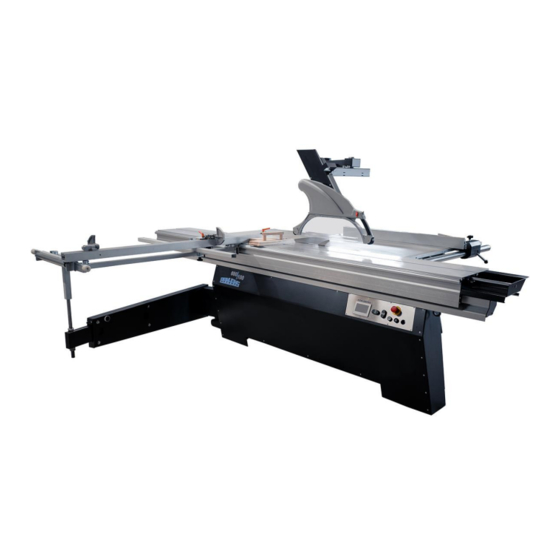
PANHANS 680 100 Manuals
Manuals and User Guides for PANHANS 680 100. We have
1
PANHANS 680 100 manual available for free PDF download: Operating Manual
PANHANS 680 100 Operating Manual (70 pages)
Brand:
PANHANS
| Category:
Saw
| Size: 4 MB
Table of Contents
Table of Contents
2
Introduction
7
Legal Notice
7
Illustrations
7
Symbols
7
General Symbols
7
Figure 1: Saw Blade
7
Symbols in Safety Instructions
8
General
9
Intended Use
9
Target Group and Previous Experience
9
Requirements for the Operators
9
Accident Prevention
10
General Safety Regulations
10
Structure and Function
11
Standard Equipment
11
Special Equipment
12
Expandability
12
Safety
13
Basic Safety Instructions
13
Application Area and Intended Use
13
Modifications and Conversions to the Machine
13
Residual Risks
14
Observe the Environmental Protection Regulations
15
Organisational Measures
16
Personnel Selection and Qualification - Basic Duties
16
Safety Instructions for Specific Phases of Operation
16
Normal Operation
16
Special Work Within the Scope of Maintenance Work as Well as Troubleshooting in the Workflow
17
Safe Working Practices
17
Hazardous Areas on the Sliding Table Saw
19
Danger Zone Saw Blade
19
Danger Zones Around the Machine
19
Figure 2: Danger Zone Saw Blade
19
Figure 3: Danger Zones Around the Machine
19
Avoidance of Kickback Hazards
20
Use Fence and Saw Blade Guard
20
Never Work Without the Riving Knife
20
Rip Fence When Cutting Short Workpieces to Width
20
Figure 4: Cutting Short Workpieces to Width
20
Parallelism of the Rip Fence
21
Cutting off Small Pieces on the Rip Fence
21
Special Characteristics of Guards Made of Polycarbonate (Plexiglas)
21
Figure 5: Fixing the Deflector Wedge on the Table
21
Effect of Cooling Lubricants on Polycarbonate
22
Machine Data
22
Technical Specifications
22
Figure 6: Nameplate
22
Technical Characteristics
23
Emission Levels
24
Noise Emission Values
24
Dimensions
25
Working Areas
25
Dimensions (Front View)
25
Figure 7: Working Areas
25
Figure 8: Dimensions (Front View)
25
Dimensions (Top View)
26
Figure 9: Dimensions (Top View)
26
Installation and Connection
27
Check Delivery Conditions
27
Transport to the Installation Site
27
Figure 10: Machine Transport
27
Levelling with a Spirit Level
28
Procedure in the Normal Case
28
Procedure in the Exceptional Case
28
Figure 11: Levelling Screws at the Rear (Normal Case)
28
Figure 12: Front Levelling Screws (Exceptional Case)
28
Lashing on a Transport Vehicle
29
Temporary Storage
29
Figure 13: Lashing Points (4 X)
29
Connecting the Extraction Unit
30
Figure 14: Upper Suction Nozzle Diameter
30
Figure 15: Lower Suction Nozzle Diameter
30
Electrical Connection
31
Back-Up Fuses (On-Site)
31
Figure 16: Electrical Connection
31
Components & Controls
32
Figure 17: Components & Controls - Front View
32
Figure 18: Components & Controls - Oblique View
32
Figure 19: Components & Controls - Top View
33
Mounting and Usage
34
Slide Table
34
Rip Fence
34
Figure 20: Slide Table Controls
34
Figure 21: Rip Fence
34
Operating the Rip Fence
35
Figure 22: Fitting the Rip Fence
35
Figure 23: Operating the Rip Fence
35
Mounting the Cross Slide
36
Moving the Cross Slide
36
Figure 24: Cross Slide Mounting
36
Figure 25: Cross Slide Clamping
36
Figure 26: Moving the Cross Slide
36
Use Cross-Cut Fence for 90° Cuts
37
Figure 27: Mount Cross-Cut Fence
37
Figure 28: Cross-Cut Fence at Zero Position
37
Figure 29: Prepare 90 Degree Cut
37
Figure 30: Abut Guide Bolt to the Angle Stop Plate
37
Use Cross-Cut Fence for Angle Cuts
38
Set Cutting Angle to 15° (Example)
38
Set Cutting Length to 93 CM (Example)
38
Figure 31: Set Angular Cuts
38
Figure 32: Adjusting the Cross-Cut Fence
38
Figure 33: Set Cutting Length
38
Use Further Flip Stops
39
Extendable Fence Guide
39
Reading the Cutting Length
39
Figure 34: Available Flip Stops
39
Figure 35: Extendable Fence Guide
39
Figure 36: Measuring Scales on the Fence Guide
39
Readjusting the Fence Rulers
40
Figure 37: Fixing Screw
40
Swivelling Saw Blade Guard
41
Change Saw Blade Guard
41
Figure 38: Swivel Arm for Saw Blade Guard
41
Figure 39: Fitting the Saw Blade Guard
41
Commissioning
42
Control Elements
42
Switching on
42
Switching off
42
Figure 40: Control Elements
42
Safety Equipment
43
Saw Blade Guard with Extraction
43
Safety Switches
43
Emergency Stop Switches
43
Operating the 4.7" Touch Display
44
Start Screen
44
Status Window
44
Figure 41: Start Screen
44
Figure 42: Status Window
44
Language Settings
45
Machine Overview
45
Saw Blade Calibration
45
Figure 43: Language Settings
45
Figure 44: Machine Overview - Current Positions and Speed
45
Calibrate Height
46
Figure 45: Saw Blade Height 50 MM
46
Figure 46: Calibrate Height
46
Figure 47: Adopt Calibration Value for Height
46
Calibrate Angle
47
Figure 48: Angular Gap
47
Figure 49: Calibrate Angle
47
Figure 50: Adopt Calibration Value for Angle
47
Date and Time (from Software Version 1.9)
48
Speed Setting
48
Figure 51: Set Date and Time
48
Figure 52: Speed Setting - Loosen V-Belt
48
Figure 53: Speed Scheme
48
Changing the Saw Blade
49
Remove Saw Blade
49
Figure 54: Remote Locking on the Slide Table
49
Figure 55: Safety Catch on the Slide Table
49
Figure 56: Fold Sawdust Flap Forwards
49
Figure 57: Saw Blade Flange
49
Insert Main Saw Blade
50
Riving Knife Setting
50
Figure 58: Riving Knife Setting (Symbolic Representation)
50
Optional Components
51
Digital Cross-Cut Fence
51
Calibration of the Digital Cross-Cut Fence
51
Figure 59: Digital Cross-Cut Fence
51
Figure 60: Display Mode MM/Abs
51
Figure 61: Stored Reference Dimension (Example)
51
Figure 62: Display Deviating from Reference Dimension
51
Change / Enter Reference Value
52
Figure 63: Change/Enter Calibration Unit 1
52
Figure 64: Change/Enter Calibration Unit 2
52
Figure 65: Change/Enter Calibration Unit 3
52
Figure 66: Change/Enter Calibration Unit 4
52
Figure 67: Change/Enter Calibration Unit 5
52
Rip Fence Left to the Saw Blade
53
Double-Sided Mitre Fences DSG-A and DSG-D
53
Figure 68: Rip Fence Mounted to the Left of the Saw Blade
53
Figure 69: Flip Stop (Left to the Saw Blade)
53
Figure 70: DSG-A (Analogue)
53
Figure 71: DSG-D (with Digital Indicator)
53
Digit PAB - Absolute Measuring System for the Rip Fence
54
Digit-PAB Features
54
Digit PAB - Operation
54
Digit PAB - Rip Fence Capacities
54
Figure 72: Digit PAB
54
Figure 73: Rip Fence with Digit-PAB
54
Power Feeder 76
55
Mounting the Power Feeder
55
Figure 74: Power Feeder 76
55
Figure 75: Mounting the Power Feeder
55
Adjustable Scoring Saw Blade "Quickstep
56
Setting the Scoring Width
56
Changing the Scoring Saw Blade
56
Figure 76: Quickstep Setting Mechanism for Scoring Saw Blade
56
Figure 77: Quickstep Quick-Release Screw
57
Manual Scoring Unit 1750
58
Figure 78: Saw Blade Flange of the Scoring Saw
58
Figure 79: Safety Catch of the Sawdust Flap
58
Adjusting the Manual Scoring Saw
59
Spraying System
59
Special Features When Using a Spraying System
59
Figure 80: Setting Wheels for Scoring Saw
59
Laser Cut-Position Indicator
60
Trimming with Laser Beam
60
Special Requirements for Use
60
Figure 81: Laser Cut-Position Indicator
60
Figure 82: Trimming with Laser Beam
60
Swivel-Away Device for the Cross Slide
61
Attaching the Swivel Arm to the Cross Slide
61
Reattaching the Cross Slide
61
Figure 83: Position and Mount Swivel Arm
61
Figure 84: Swivel Away Cross Slide
61
Figure 85: Final Parking Position
61
Troubleshooting
62
General Faults
62
Fault Messages on the Touchscreen
63
Figure 86: Error Message 1
63
Figure 87: Error Message 2
63
Figure 88: Error Message 3
63
Figure 89: Error Message 4
63
Figure 90: Error Message 5
63
Figure 91: Error Message 6
63
Figure 92: Error Message 7
63
Retightening / Changing the V-Belt
64
Figure 93: V-Belt Tightness
64
Maintenance and Inspection
65
Lubrication Guide
65
Figure 94: Lubrication Points on the Height Adjustment
65
Options and Accessories
66
Aggregates
66
Machine Operation
66
Optional Fence Systems
66
Slide Table and Additional Supports
67
Support Systems
68
Special Accessories
68
Disassembly and Scrapping
69
EU - Declaration of Conformity
70
Advertisement
Advertisement
Related Products
PANHANS 680|200
PANHANS 690
PANHANS 690|200
PANHANS 100
PANHANS 3V
PANHANS BSB 400
PANHANS BSB 500
PANHANS BSB 600
PANHANS BSB 700
PANHANS BSB 800
PANHANS Categories
Saw
Power Tool
Planer
Control Unit
Controller
More PANHANS Manuals
Login
Sign In
OR
Sign in with Facebook
Sign in with Google
Upload manual
Upload from disk
Upload from URL