GDC SR-1000 Installation Manual
Standalone integrated media block
Hide thumbs
Also See for SR-1000:
- User manual (137 pages) ,
- User & installation manual (42 pages) ,
- Installation manual (22 pages)

Related Manuals for GDC SR-1000


Summary of Contents for GDC SR-1000
- Page 1 INSTALLATION MANUAL FOR SR-1000 STANDALONE INTEGRATED MEDIA BLOCK™ SMS Version 17.0 February 07 , 2022...
-
Page 2: Table Of Contents
IMB Network Setup ................... 14 STORAGE CONFIGURATION ..............16 SERIES 2 PROJECTOR SETUP ..............18 IMB Marriage and Clearing the Service Door Tamper from the SR-1000 .. 18 Barco Series 2 Projector Setup ..............19 NEC Series 2 Projector ................20 Christie Series 2 Projector................. - Page 3 15 SR-1000 INPUT AND OUTPUT ..............40 15.1 AES Audio and GPIO Pinout ..............40 15.2 Audio AES 17-24 Pinout (for SR-1000 Extreme -24) ......... 40 15.3 GPIO Power Details .................. 41 15.4 Audio Output from the SR-1000 ..............42 15.5...
- Page 4 The contents, features and specifications stated in this manual are subject to change without notice due to continuous product development and improvements. In no other event shall GDC Technology Limited be liable for any loss of profit or any other commercial damages, including but not limited to special, consequential, or other damages.
- Page 5 CONTACTS AND OFFICES CONTACTS AND OFFICES Website Contact Us Worldwide Offices 24/7 Support February 07 , 2022 INSTALLATION MANUAL FOR SR-1000 - 4 - STANDALONE INTEGRATED MEDIA BLOCK™...
-
Page 6: Introduction
This document is a guide through the process of setting up the SR-1000 with the projector, audio system, and automation devices used in cinema theatres. In this manual, the SR-1000 Web UI is used to configure the SR-1000. The Dashboard of the SR- 1000 Web UI is shown below (Refer to Figure 1). -
Page 7: Equipment List
1.INTRODUCTION 1.1 Equipment List This section provides a suggested installation configuration of GDC SR-1000 for reference. Please contact our sales representative to specify the accessories needed for the installation. The SR-1000 Packaging Includes: Item Photo SR-1000 Unit with projector cover plate... -
Page 8: Installing Sr-1000 Into The Projector
This section of the manual describes the physical installation of the SR-1000 into the projector. If the projector does not have the GDC SR-1000 installed, follow the steps below to install the SR- 1000 into the projector. ™... -
Page 9: Remove Existing Interface Board/Placeholders From The Projector
2.1.1 Barco Projector Placement Figure 3 shows an interface board (with SMPTE 292 inputs) connected to a Barco projector. This board must be removed in order to install the SR-1000, as shown in Figure 4. Figure 3: Remove interface board from Barco projector... -
Page 10: Christie Projector Placement
NOTE: When installing the SR-1000 into any NEC projector, it is recommended to install it into the top slot of the projector. If the SR-1000 is installed into the bottom slot, the board runs the risk of coming in contact with the IMB enclosure. -
Page 11: Installing The Sr-1000 Into The Projector
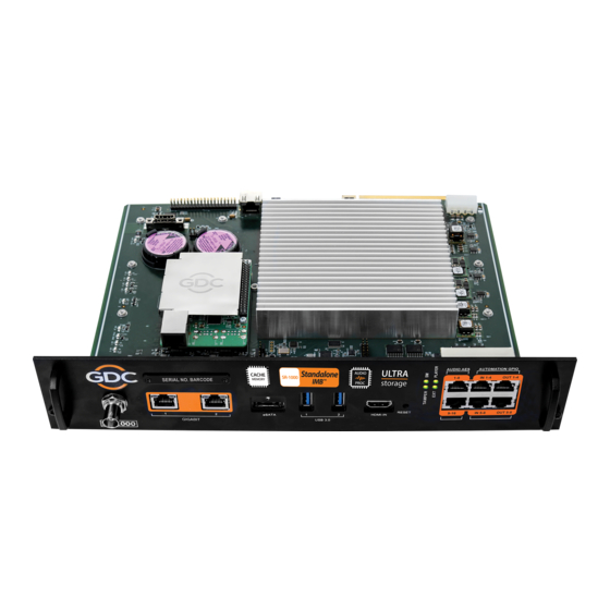
Figure 7: Installing the SR-1000 into the projector Insert the SR-1000 as shown in Figure 7. The SR-1000 should slide into the projector on the rails provided by the IMB slot, and the SR-1000 faceplate should be flush with the other existing faceplates once properly inserted. -
Page 12: Connecting Portable Storage/Enterprise Storage With The Sr-1000
Figure 8: Connect eSATA cable to the Portable Storage Making the connections to the SR-1000 3. Insert the eSATA cable into the SR-1000 eSATA port. Figure 9: Insert eSATA cable into SR-1000 eSATA port NOTE: To use Portable Storage as the content source, it MUST be connected to the eSATA port of the SR-1000 board. -
Page 13: Connecting The Enterprise Storage
Figure 10: Connect eSATA cable to the Enterprise Storage Making the connections to the SR-1000 3. Insert the eSATA cable into the SR-1000 eSATA port. Figure 11: Insert eSATA cable into SR-1000 eSATA port NOTE: To use the Enterprise Storage as the content source, it MUST be connected to the eSATA port of the SR-1000 board. -
Page 14: Sr-1000 Web Ui Access
2. The SR-1000 Web UI can be accessed by a web browser (Google Chrome or Mozilla Firefox are recommended). 3. Enter the IP address of the SR-1000 in the web browser, to access the login page on the Web UI. The default IP address of the SR-1000 is 192.168.1.12. -
Page 15: Sr-1000 Ip Address Setup
5. SR-1000 IP ADDRESS SETUP 5 SR-1000 IP ADDRESS SETUP The IP address of the SR-1000 IMB will need to be set for proper operation. 5.1 IMB Network Setup Change the IP addresses of the SR-1000 using the following steps: Login as Maintenance user. - Page 16 5. SR-1000 IP ADDRESS SETUP If all of the IP addresses are valid, a popup window will appear as shown in Figure 14. Figure 14: Network Configuration settings Click OK to exit. Click Save to save the settings. February 07...
-
Page 17: Storage Configuration
3. Go to Dashboard, click Restart, followed by OK to confirm. This is to ensure all components in the SR-1000 are able to detect the selected storage after restart. 4. The SR-1000 will restart and use the selected option for storage. - Page 18 If Priority is set as ‘IMB Storage’, then ‘Portable/Enterprise Storage’ should be selected as Primary Storage in Storage Type with the option of selecting ‘CineCache’ as Secondary Storage. February 07 , 2022 INSTALLATION MANUAL FOR SR-1000 - 17 - STANDALONE INTEGRATED MEDIA BLOCK™...
-
Page 19: Series 2 Projector Setup
7.1 IMB Marriage and Clearing the Service Door Tamper from the SR-1000 Follow the steps below to perform the marriage between the SR-1000 and to clear the service door tamper on the SR-1000: Under the Configuration tab in the menu, click the System sub-tab. -
Page 20: Barco Series 2 Projector Setup
Service Door/Marriage Tamper on the server must be cleared before the SR-1000 can be used for playback. In order to use the SR-1000 for content playback, the INPUT source of the projector macros should be set to “Mediablock” (as shown in Figure 19). If the input file is not present, please download and install the latest projector configuration files for your projector. -
Page 21: Nec Series 2 Projector
7. SERIES 2 PROJECTOR SETUP 7.3 NEC Series 2 Projector In order to configure an NEC Series 2 projector to work with the SR-1000, the following steps must be taken: 1. Switch on the projector so that it is in STANDBY mode. -
Page 22: Christie Series 2 Projector
7. SERIES 2 PROJECTOR SETUP To use the SR-1000 for content playback, the INPUT source of the projector macros must be set to IMB. 7.4 Christie Series 2 Projector In order to configure a Christie Series 2 projector to work with the SR-1000, the following steps must be taken: 1. - Page 23 5. Select [GDC] for the [IMB Installed] (as shown in Figure 25). Figure 25: Content Devices Configuration 6. Clear the Service Door/Marriage Tamper on the SR-1000. To use the SR-1000 for content playback, the INPUT for projector channel must be set to [IMB- Generic]. February 07...
-
Page 24: Settings For Series 2 Projectors
The settings for 3D output control (‘3D Sync Polarity’, ‘Dark Time’, ‘Output Delay’ and ‘Phase Delay’) should be customized according to the type of 3D system used (RealD, XpanD or Dolby3D). February 07 , 2022 INSTALLATION MANUAL FOR SR-1000 - 23 - STANDALONE INTEGRATED MEDIA BLOCK™... -
Page 25: Time Zone Setup
8. TIME ZONE SETUP 8 TIME ZONE SETUP The SR-1000 may or may not arrive with the local time zone set. The following steps show how to change the time zone on the server. 1. Under the Configuration tab in the menu, click the System sub-tab. -
Page 26: Content Ingest Management Setup
9. CONTENT INGEST MANAGEMENT SETUP 9 CONTENT INGEST MANAGEMENT SETUP An ingest source must be configured before content can be transferred to the SR-1000. This section shows the configuration for content ingest from two different source types. The same steps can be used to set up content ingest sources using other sources. -
Page 27: Content Ingest From Ftp
Figure 29: Content source settings 6. Click Open to connect to the FTP server and choose the content for ingest. Figure 30: Content source settings February 07 , 2022 INSTALLATION MANUAL FOR SR-1000 - 26 - STANDALONE INTEGRATED MEDIA BLOCK™... -
Page 28: Audio Setup
10. AUDIO SETUP 10 AUDIO SETUP The SR-1000 features AES digital audio signal via two RJ45 Outputs. For compatibility with most audio processors on the market, a standard RJ45 to DB25 connector is included in the packaging (please refer to Figure 31). - Page 29 10. AUDIO SETUP Figure 34: AES Audio RJ45 pinout February 07 , 2022 INSTALLATION MANUAL FOR SR-1000 - 28 - STANDALONE INTEGRATED MEDIA BLOCK™...
-
Page 30: Subtitles
It is recommended to use subtitle overlay for subtitle display. To do so, please check Subtitle Overlay Option and mention the Subtitle Delay interval under the Playback sub-tab of the Configuration menu. Figure 35: Subtitle settings February 07 , 2022 INSTALLATION MANUAL FOR SR-1000 - 29 - STANDALONE INTEGRATED MEDIA BLOCK™... -
Page 31: Automation Setup
12. AUTOMATION SETUP 12 AUTOMATION SETUP The SR-1000 is able to control external devices using its automation interface. This can be used to automate repetitive tasks for the cinema operator to prevent user error. 12.1 Automation setup for server GPIO The SR-1000 GPIO automation device settings can be configured using the steps below: 1. -
Page 32: Automation Setup For Projectors
12. AUTOMATION SETUP 12.2 Automation setup for projectors The SR-1000 supports automation for Barco, Christie and NEC projectors. Follow the steps below to configure a projector device in the server automation interface. 1. Under the Automation tab in the menu, click the Device sub-tab. -
Page 33: Automation Setup For Ecna Devices
12. AUTOMATION SETUP 12.3 Automation setup for eCNA devices The SR-1000 supports the eCNA-10 automation system. Follow the steps below to configure an eCNA device in the server automation interface. 1. Under the Automation tab in the menu, click the Device sub-tab. -
Page 34: Automation Setup For Jnior Devices
12. AUTOMATION SETUP 12.4 Automation setup for JNIOR devices The SR-1000 supports the JNIOR Ethernet I/O controller device. Follow the steps below to configure a JNIOR device in the server automation interface. 1. Under the Automation tab in the menu, click the Device sub-tab. -
Page 35: Automation Setup For Christie Act Devices
12. AUTOMATION SETUP 12.5 Automation setup for Christie ACT devices The SR-1000 supports the Christie ACT automation device. Follow the steps below to configure a Christie ACT device in the server automation interface. 1. Under the Automation tab in the menu, click the Device sub-tab. -
Page 36: Automation Setup For Dolby Devices
12. AUTOMATION SETUP 12.6 Automation setup for Dolby devices The SR-1000 supports automation for the Dolby sound processors. Follow the steps below to configure a Dolby device in the server automation interface. For this example, the device refers to the Dolby CP650 Sound Processor. -
Page 37: Automation Setup For Usl Dax Devices
12. AUTOMATION SETUP 12.7 Automation setup for USL DAX devices The SR-1000 supports automation for USL DAX sound processor. Follow the steps below to configure a USL DAX device in the server automation interface. 1. Under the Automation tab in the menu, click the Device sub-tab. -
Page 38: Automation Setup For Usl Jsd Devices
12. AUTOMATION SETUP 12.8 Automation setup for USL JSD devices The SR-1000 supports automation for USL JSD-80 and JSD-100 sound processor. Follow the steps below to configure a USL JSD device in the server automation interface. 1. Under the Automation tab in the menu, click the Device sub-tab. -
Page 39: Component Enginnering Ta-10 Setup
13. COMPONENT ENGINNERING TA-10 SETUP 13 COMPONENT ENGINNERING TA-10 SETUP The Component Engineering TA-10 can be used for theater automation with the SR-1000. It requires that the TA-10 be wired in a particular configuration. A wiring diagram can be seen in Figure 44. -
Page 40: Testing Procedures For Qc After Installation
SR-1000 has been properly installed: 1. Test the video playback capabilities of the SR-1000. 2. Test the audio playback capabilities of the SR-1000 and verify that all the channels are working. Also check for any static noises. 3. Test the server’s ability to activate automation cues using test cues for lights, curtains, sound and fire alarm. -
Page 41: Sr-1000 Input And Output
Figure 45: AES audio and GPIO pinout 15.2 Audio AES 17-24 Pinout (for SR-1000 Extreme -24) Figure 46 describes the pinout for the Audio AES 17-24 connector on the SR-1000 Extreme -24. Audio AES 17-24 Figure 46: AUX AES Pinout... -
Page 42: Gpio Power Details
15. SR-1000 INPUT AND OUTPUT 15.3 GPIO Power Details GPIO Input Details ------------------- Vin High min level is 3.5 Volts Vin Low max level is 1.5 Volts Iin min -20 uA Iin max +20 uA (Essentially no current flows; this is a voltage sensing device) The GPI inputs have a 5.62K Ohm resistor pull-up to an isolated 5 Volts. -
Page 43: Audio Output From The Sr-1000
15.5 Audio Input to the SR-1000 15.5.1 HDMI Input SR-1000 allows direct input of 7.1 channel PCM audio via HDMI IN port on the IMB. The HDMI output of the source needs to be set to LPCM audio format. February 07... -
Page 44: Examples Of A Complete Audio Input/Output Solution (For 5.1/7.1 Audio Formats)
Figure 47. AES3 digital audio outputs (Channels 1 to 8) from the SR-1000 are fed to the digital inputs on the AIB-2000 and converted to analog outputs which can be interfaced with analog audio equipment. -
Page 45: Connections Requirements
AIB-2000 to the inputs of analog Amplifiers/Crossovers Connection to analog Amplifier using appropriate line level audio cables and connectors. AES output pair 11 and 12 on the SR-1000 carries the Hi and Vi-N channels respectively (assuming DCP’s follow the 16-channels ISDCF recommended channel order). - Page 46 An HDMI source can be connected to the HDMI IN on Connecting an HDMI source the faceplate of the SR-1000, using an HDMI cable. A Booth monitor can be connected to the LCR mon output on the back panel of the AIB-2000 using an RCA Connector.
-
Page 47: Audio Input/Output Solution Using Aib-2000 (Suitable For Connection To Digital Amplifiers)
AES3 digital output from the SR-1000 may be fed directly to the amplifier's digital inputs and only the analog sources may be routed via the AIB-2000 to the analog inputs of the Amplifiers. -
Page 48: Connection Requirements
Hi/Vi-N device and 2-channel D/A converter (if used). AES output pair 15 and 16 on the SR-1000 carries the LTC signal used to sync 4D systems like ScreenX, 4DX and MX4D to the SR-1000. - Page 49 An HDMI source can be connected to the HDMI IN on Connecting an HDMI source the faceplate of the SR-1000, using an HDMI cable. AES pair 9/10 on the SR-1000 carries a mix of L+C+R which can be used as a monitor output. Connecting a Booth Monitor...
-
Page 50: Technical Specifications Of Aib-2000
15. SR-1000 INPUT AND OUTPUT 15.7 Technical Specifications of AIB-2000 Figure 49: AIB-2000 – Front and Back Panels Frequency range 20 Hz - 20,000 Hz Microphone input XLR female Microphone switch Microphone in on/off Microphone input HPF 100 Hz 12 dB/oct switchable... - Page 51 Contact Us GDC Technology manufacturing facility is ISO 9001:2015 certified. Copyright © 2022 GDC Technology Limited. All Rights Reserved. All trademarks listed in this manual are properties of their respective owners. Specifications are subject to change without notice due to ongoing product development and improvement.