
Related Manuals for Fire-Lite Alarms MRP-4424


Summary of Contents for Fire-Lite Alarms MRP-4424
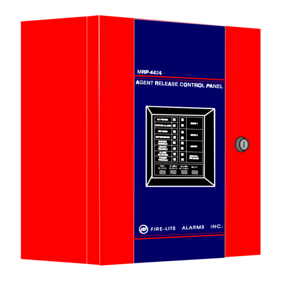
- Page 1 The MRP-4424 Agent Release Control Panel DOCUMENT 15180 03/12/97 Rev: 12 Clintonville Road, Northford CT 06472 ECN 96-433 Technical Manuals Online! - http://www.tech-man.com firealarmresources.com...
- Page 2 Technical Manuals Online! - http://www.tech-man.com firealarmresources.com...
-
Page 3: Table Of Contents
3.4 Output Circuits ....................17 3.5 Power ......................... 18 3.6 Optional Modules ....................20 3.7 Setting MRP-4424 Mode of Operation ............... 25 Appendix A: Battery Calculations ............27 Appendix B: NFPA Standard-Specific Requirements ......29 Trouble Shooting Table ................36... -
Page 4: I Nfpa Standards
I NFPA Standards The MRP-4424 complies with the following NFPA standards: NFPA 12 CO Extinguishing Systems (High Pressure Only) NFPA 12A Halon 1301 Extinguishing Systems NFPA 12B Halon 1211 Extinguishing Systems NFPA 72-1993 Central Station Signaling Systems (Automatic, Manual, and Waterflow). Protected Premises Unit (Requires NOTI-FIRE 911A/911AC DACT or MS-5012 Slave Communicator). -
Page 5: The Mrp-4424
1.0 The MRP-4424 Features • Microprocessor-controlled • Disable/enable controls per Initiating Device • Power-limited on all circuits except Municipal Box Circuits output • Last Event Recall • Alarm and trouble resound • Battery/Earth fault supervision • Four Style B/D Initiating Device Circuits •... - Page 6 Figure 1.0-1: MRP-4424 Installation Diagram MRP-4424 Document 15180 Rev D 03/12/97 15180:D Technical Manuals Online! - http://www.tech-man.com firealarmresources.com...
-
Page 7: Optional Boards
Optional Boards The MRP-4424 has mounting slots for two option boards. Any two of the following three option modules may be installed. Transmitter Module (4XTMF) The Transmitter Module provides a supervised output for local energy municipal box transmitter (for NFPA 72-1993 Auxiliary Fire Alarm System) and alarm and trouble reverse polarity circuits (for NFPA 72-1993 Remote Station Fire Alarm System). -
Page 8: Remote Annunciator
The Meter Module provides a voltmeter to measure the voltage across the batteries and an ammeter to measure the charging current to the batteries. The meters are provided as a assembly that mounts to the lower left-hand corner of the cabinet. MRP-4424 Document 15180 Rev D 03/12/97 15180:D Technical Manuals Online! - http://www.tech-man.com... -
Page 9: Specifications
Total DC current available for powering external devices is 0.5 amp (subtracted from 2.25 amps available to notification appliance circuits). Maximum ripple voltage: 100 mV p/p Note: For device compatibility, refer to the Device Compatibility Chart, Document 15384. MRP-4424 Document 15180 Rev D 03/12/97 15180:D Technical Manuals Online! - http://www.tech-man.com... - Page 10 Cabinet = 5.375" Backbox = 4.750" Door = 14.625" Backbox = 14.5" Door = 16.125" Backbox = 16" Optional Trim Ring TR-4XRF Figure 1.6-1: Cabinet Dimensions MRP-4424 Document 15180 Rev D 03/12/97 15180:D Technical Manuals Online! - http://www.tech-man.com firealarmresources.com...
-
Page 11: System Operation
(not visible through door). MICRO FAIL Yellow LED that illuminates on motherboard when watchdog timer detects microprocessor failure (not visible through door). MRP-4424 Document 15180 Rev D 03/12/97 15180:D Technical Manuals Online! - http://www.tech-man.com... -
Page 12: Control Switches
SILENCE), at which point the LED(s) will illumi- ZONE 1 nate steadily. TROUBLE LED ALARM LED ZONE 2 TROUBLE LED ABORT LED ABORT ABORT TROUBLE LED MANUAL RELEASE MANUAL RELEASE MANUAL RELEASE TROUBLE LED MRP-4424 Document 15180 Rev D 03/12/97 15180:D Technical Manuals Online! - http://www.tech-man.com firealarmresources.com... -
Page 13: Supervisory
Output circuit #4 is used as an input for monitoring supervisory devices such as valve tamper switches (note that SW1 DIP switch #2 must be set "ON" -- see section "Setting MRP-4424 Mode of Operation"). By setting Switch short circuit on this input (activation of a N.O. contact) will cause the supervisory LED to flash. -
Page 14: Installation Procedure
0.25" away from any non-power limited circuit wiring. Furthermore, all power limited circuit wiring and non-power limited circuit wiring must enter and exit the cabinet through different knockouts and/or conduits. A typical wiring diagram for the MRP-4424 is shown below. -
Page 15: Initiating Device Circuits
(part # 71252 UL listed) Heat Detector Manual Pull Station B+ A+ IDC #1 IDC #2 IDC #3 IDC #4 Figure 3.2-1: Example of Initiating Device Circuits MRP-4424 Document 15180 Rev D 03/12/97 15180:D Technical Manuals Online! - http://www.tech-man.com firealarmresources.com... -
Page 16: 4-Wire Smoke Detector Connections
24V power loop which must function at the same time in alarm. is the detector current in alarm. is the end-of-line relay current. MRP-4424 Document 15180 Rev D 03/12/97 15180:D Technical Manuals Online! - http://www.tech-man.com... -
Page 17: Output Circuits
Output Circuits Notification Appliance Circuits The MRP-4424 can provide two Style Y/Z Notification Appliance Circuits and two Style Y Releasing Circuits (see section "Setting MRP-4424 Mode of Operation" for DIP switch configuration). Each circuit is capable of 1.5 amps of current. Total current drawn from all four circuits cannot exceed 2.25 amps. -
Page 18: Power
TB2 Terminals 1 (+) and 2 (-). nals 1(+) and 2 (-). Terminals 3 (+) and 4 (-). +24VU +24VR +24VNR Figure 3.5-1: Diagram of Power Terminals MRP-4424 Document 15180 Rev D 03/12/97 15180:D Technical Manuals Online! - http://www.tech-man.com firealarmresources.com... - Page 19 "AMP" and connect cable assembly P2 to pin connector J2 and cable assembly P3 to pin connector J3 on the main board. Secure the 4XMMF to the backbox with the two screws provided. Figure 3.5-2: Diagram of the 4XMMF Voltmeter connected to the Main Board MRP-4424 Document 15180 Rev D 03/12/97 15180:D Technical Manuals Online! - http://www.tech-man.com...
-
Page 20: Optional Modules
Optional Modules The MRP-4424 has two module connectors - J5 and J8. Three modules are available for the panel and they can be used in any combination, including duplicate modules (see notes below). The corresponding option jumper must be cut before installation of an optional module. - Page 21 Affix the terminal identification labels provided with the option modules as shown below. (Part # 42050) Stand-offs Option Board Main (4XZMF shown) Board Figure 3.6-2: Installing Option Modules MRP-4424 Document 15180 Rev D 03/12/97 15180:D Technical Manuals Online! - http://www.tech-man.com firealarmresources.com...
- Page 22 Municipal Box. Cutting the TBL jumper will allow the alarm reverse polarity circuit to open on trouble, if no alarm exists. Note: Remote Alarm, Remote Trouble and Municipal Box wiring can leave the building. MRP-4424 Document 15180 Rev D...
- Page 23 Note: Refer to the Protected Premises Unit label, located on the door of the control panel, to indicate if any dry contacts are to be used as non-power limited dry contacts. MRP-4424 Document 15180 Rev D 03/12/97 15180:D Technical Manuals Online! - http://www.tech-man.com...
- Page 24 Side View Front View Note: Make wiring connections with system power off. Maximum wire impedance is 50 ohm per wiring connection. Figure 3.6-3: LED Interface Module -- 4XLMF MRP-4424 Document 15180 Rev D 03/12/97 15180:D Technical Manuals Online! - http://www.tech-man.com...
-
Page 25: Setting Mrp-4424 Mode Of Operation
3 . 7S e t t i n g M R P - 4 4 2 4 M o d e o f O p e r a t i o n T h e D I P s w i t c h i s l o c a t e d a t t h e b o t t o m o f t h e M R P - 4 4 2 4 m a i n b o a r d . - Page 26 O u t p u t 4 S u p e r v i s o r y / R e l e a s i n g S e r v i c e S e t t h e f u n c t i o n o f O u t p u t 4 v i a S W 1 D I P s w i t c h 2 . 2 O F S w i t c h 4 w i l l f...
-
Page 27: Appendix A: Battery Calculations
A : B a t t e r y C a l c u l a t i o n s A p p e n d i x S t a n d b y B a t t e r y R e q u i r e m e n t s T a b l e A - 1 : T h e S t a n d b y B a t t e r y C u r r e n t f i g u r e o b t a i n e d i n T a b l e A - 1 r e p r e s e n t s t h e a m o u n t o f c u r r e n t t h a t m u s t... - Page 28 bl e A - 2 : A m p e r e - H o u r C a l c u l a t i o n s S t a n d b y B a t t e r y C u r r e n t S t a n d b y T i f r o m T a b l e 1 2 4 , 6 0 o r 9 0 h o u r s C o n v e r t t h e t o t a l...
-
Page 29: Appendix B: Nfpa Standard-Specific Requirements
B : N F P A S t a n d a r d - S p e c i f i A p p e n d i x c R e q u i r e m e n t s T h e F i r e •... - Page 30 F i g u r e B - 1 A : N F P A 7 2 - 1 9 9 3 S i g n a l i n g S y s t e m s f o r C e n t r a l S t a t i o n S e r v i c e ( P r o t e c t e d P r e m i s e s U n i t ) a n d R e m o t e S t a t i o n F i r e A l a r m S y s t e m ( P r o t e c t e d P r e m i s e s U n i t )
- Page 31 DACT, when employing a DACT. This directs the control panel to transmit all trouble conditions except AC LOSS. y l l y l l y l l MRP-4424 Document 15180 Rev D 03/12/97 15180:D Technical Manuals Online! - http://www.tech-man.com firealarmresources.com...
- Page 32 RESET SILENCE MODE yellow Black 120 VAC yellow 12VDC Battery Neutral 2-7AH Black Ground White Green AC Wiring for DACT/FACP must be connected to the same circuit. MRP-4424 Document 15180 Rev D 03/12/97 15180:D Technical Manuals Online! - http://www.tech-man.com firealarmresources.com...
- Page 33 Note: Maximum loop resistance allowed for wiring from control panel to Municipal Box is 3 ohms. Municipal Box Circuit Gamewell Model M34-56 Local Energy Municipal Box Note: Municipal Box wiring can leave the building. 4XTMF Transmitter Module (activated polarities shown) MRP-4424 Document 15180 Rev D 03/12/97 15180:D Technical Manuals Online! - http://www.tech-man.com firealarmresources.com...
- Page 34 UL listed + - + - Remote Alarm Remote Trouble Note: Remote Alarm and Remote Trouble wiring can leave the building. 4XTMF Transmitter Module (activated polarities shown) MRP-4424 Document 15180 Rev D 03/12/97 15180:D Technical Manuals Online! - http://www.tech-man.com firealarmresources.com...
- Page 35 Company Bulletin # 748. 3) This control panel/transmitter arrangement can be employed for NFPA 72-1993 Proprietary Fire Alarm Systems. MRP-4424 Notes: 1) Form-C Alarm contact programmed to activate on General Alarm. 2) Form-C Trouble contact which will automatically activate on any Trouble condition.
-
Page 36: Trouble Shooting Table
MRP-4424 Document 15180 Rev D 03/12/97 15180:D Technical Manuals Online! - http://www.tech-man.com firealarmresources.com... - Page 37 NOTES MRP-4424 Document 15180 Rev D 03/12/97 15180:D Technical Manuals Online! - http://www.tech-man.com firealarmresources.com...
- Page 38 NOTES MRP-4424 Document 15180 Rev D 03/12/97 15180:D Technical Manuals Online! - http://www.tech-man.com firealarmresources.com...
- Page 39 NOTES MRP-4424 Document 15180 Rev D 03/12/97 15180:D Technical Manuals Online! - http://www.tech-man.com firealarmresources.com...
- Page 40 Limited Warranty Fire-Lite ® warrants its products to be free from defects in materials and workmanship for eighteen (18) months from the date of manufacture, under normal use and service. Products are date stamped at time of manufacture. The sole and exclusive obligation ®...
Need help?
Do you have a question about the MRP-4424 and is the answer not in the manual?
Questions and answers