
Related Manuals for Fire-Lite Alarms MS-5024UD


Summary of Contents for Fire-Lite Alarms MS-5024UD
- Page 1 PN: 15140:G ECN 01-685 Fire Alarm Control Panel MS-5024UD/MS-5024UDE Document #15140 01/02/02 Revision...
- Page 2 While a fire alarm system may lower insurance Fire Alarm System Limitations rates, it is not a substitute for fire insurance! An automatic fire alarm system–typically made up of smoke Heat detectors do not sense particles of combustion and detectors, heat detectors, manual pull stations, audible warn- alarm only when heat on their sensors increases at a prede- ing devices, and a fire alarm control with remote notification termined rate or reaches a predetermined level.
- Page 3 Installation Precautions Adherence to the following will aid in problem-free installation with long-term reliability: WARNING - Several different sources of power can be con- Like all solid state electronic devices, this system may nected to the fire alarm control panel. Disconnect all sources operate erratically or can be damaged when subjected to light- of power before servicing.
- Page 4 Notes Document #15140 Rev.G 01/02/02 P/N 15140:G...
-
Page 5: Table Of Contents
Table of Contents CHAPTER 1: Product Description ......................... 10 1.1: Product Features ............................10 FIGURE 1-1: Optional DP-5024UD....................11 FIGURE 1-2: MS-5024UD Panel ......................12 1.2: Controls and Indicators ..........................13 FIGURE 1-3: Controls and Indicators ....................13 1.3: Circuits ................................13 1.4: Digital Communicator..........................14 1.5: Components..............................14 1.5.1: Main Circuit Board ...........................14... - Page 6 Table of Contents FIGURE 2-13: Wiring the RZA-5F/ADM-24 ..................29 FIGURE 2-14: Installing the Annunciator (Single-Gang Electrical Box) ...........29 2.8.3: PRT-24 Printer Interface Module ......................30 FIGURE 2-15: Remote Printer Connections..................30 2.8.4: RM-5F Five-Zone Relay Module......................31 FIGURE 2-16: RM-5F Installation and Wiring ...................31 2.8.5: CAC-5F Class A Converter Module ....................32 FIGURE 2-17: CAC-5F Style D Converter ..................32 CHAPTER 3: Programming Instructions.......................33...
- Page 7 Table of Contents TABLE 5-3: Battery Voltage.......................65 5.3.5: NAC 1 & 2 ............................66 5.3.6: Resettable Power..........................66 5.4: Lamp Test ..............................66 5.5: Print Mode..............................66 CHAPTER 6: Slave Communicator Configuration ....................67 FIGURE 6-1: Slave Communicator Connections................68 CHAPTER 7: Remote Site Upload/Download .......................69 7.1: Downloading Program ..........................69 7.1.1: Security Features..........................70 7.2: Downloading Initiated at Control Panel......................71...
- Page 8 This control panel has been designed to comply with standards set forth by the following regulatory agencies: • Underwriters Laboratories Standard UL 864 • NFPA 72 National Fire Alarm Code for Local, Remote Station and Central Station Fire Alarm System Before proceeding, the installer should be familiar with the following documents.
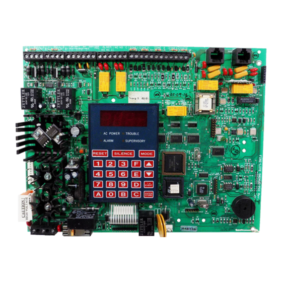
- Page 9 MS-5024UD Main Circuit Board Document #15140 Rev.G 01/02/02 P/N 15140:G...
-
Page 10: Chapter 1: Product Description
Fire•Lite Upload/Download software P/N PK-5024UD, may serve as a Service Terminal. This allows download of the entire program or upload of the entire program, history file, walktest data, current status and system voltages. The MS-5024UDE offers the same features as the MS-5024UD but allows connection to 220/ 240 VAC input. - Page 11 AC POWER TROUBLE ALARM SUPERVISORY RESET SILENCE MODE EVENT ENTER STORE Note: Unless otherwise specified, MS-5024UD shall be used in this manual to refer to both the MS-5024UD and MS-5024UDE Fire Alarm Control Communicators. Document #15140 Rev.G 01/02/02 P/N 15140:G...
- Page 12 Software for the Fire Alarm Control Communicator is located in a PROM inserted in the IC socket labeled U23. The MS-5024UD and MS-5024UDE each contain unique software. For specific panel software infor- mation, refer to the MS-5024UD(E) Field Software Change Procedure Document #50125.
-
Page 13: Controls And Indicators
Controls and Indicators Controls and Indicators Front Panel Switches Controls and Indicators FIGURE 1-3: RESET Digits 0-9 SILENCE MODE Up Arrow Down Arrow 1st EVENT ENTER/STORE Displays • Alarm - red LED • Trouble - yellow LED • Supervisory - yellow LED •... -
Page 14: Digital Communicator
Digital Communicator Notification Appliance Circuits Two Notification Appliance Circuits configurable for Style Y (Class B) or Style Z (Class A) with various program- mable features. Relays Two dry Form-C relay contacts for system alarm and system trouble are provided. Contacts are rated 2 amps @ 30 VDC and 0.5 amps @ 30 VAC resistive. -
Page 15: 3: Transformer Assembly
The RM-5F option module provides five Form-C relays which track zones 1 through 5. The module mounts to con- nector J7 on the lower right side of the main circuit board. Refer to Figure 1-2, “MS-5024UD Panel,” on page 12 and Figure 2-16 on page 31. -
Page 16: 5: Prt-24 Printer Interface Module
This kit includes one 3½" diskette plus Instruction Manual P/N 50041. When the software is loaded into an IBM compatible computer, it creates an off-line Service Terminal that allows any MS-5024UD panel to be uploaded or downloaded over standard telephone lines. - Page 17 Specifications Notification Appliance Circuits - TB5 & TB6 Nonregulated, special purpose power, Styles Y and Z supported Power-limited circuitry Operating Voltage: Nominal 24 volts Current for all external devices: 3.0 amps expandable to 5.6 amps Current-limit: PTC Maximum signaling current/circuit: 2.5 amps End-of-Line resistor: 4.7K ohms, ½...
-
Page 18: Telephone Requirements And Warnings
Manufacturer: Fire•Lite Alarms, Inc. One Fire-Lite Place Northford, CT 06472 Product Model Number: MS-5024UD FCC Registration Number: 1W6USA-20004-AL-E Ringer Equivalence 1.3B Note: The FCC ID label is located on the inside of the control panel door 1.8.3 Telephone Company Rights and Warnings The telephone company, under certain circumstances, may temporarily discontinue services and/or make changes in its facilities, services, equipment or procedures which may affect the operation of this control panel. -
Page 19: Chapter 2: Installation
Installation Installation CHAPTER 2 Mounting Options MS-5024UD Cabinet FIGURE 2-1: The cabinet may be either surface mounted or semi-flush mounted using the optional Trim Ring P/N: TR-1-R. The door is removable during the installation period by opening and lifting the door off the hinges. The cabinet mounts using two key slots and two additional 0.25"... - Page 20 Backbox Mounting Cabinet Dimensions and Knockout Locations FIGURE 2-2: 2.875” (7.3 cm) Draw wires through the respective knockout locations. Depth = 3.000” Backbox = 14.5” (7.62 cm) (36.8 cm) 0.75”(1.9 cm) 2.7” (6.86cm) 9.1” (23.1 cm) 10.375” (26.35 cm) Height=15.000” (38.10 cm) Backbox Mounting Holes 1.125”...
- Page 21 Backbox Mounting Backbox and Battery Box FIGURE 2-3: Depth = 2.875" (7.3 cm) Depth = 3.050“ Door = 14.677 “ (37.28 cm) (7.75 cm) Door = 15.342“ (38.97 cm) Bottom Depth = 4.75 (12.065 cm) Battery Box = 8.5“ (21.59 cm) Battery Box = 14.5“...
-
Page 22: Operating Power
Primary Power Source (AC) and Earth Ground Connections AC power connections are made inside the control panel cabinet. The primary power source for the MS-5024UD is 120 VAC, 60 Hz, 2.3 amps and for the MS-5024UDE is 220/240 VAC, 50 HZ, 1.2 amps. Run a pair of wires (with ground conductor) from the protected premises main breaker box to TB1 of the main circuit board. -
Page 23: Input Circuits
UL listed compatible 2-wire smoke detector UL listed compatible 2-wire smoke detector Manual Pull Station Manual Pull Station Heat Detector Heat Detector Dummy load all unused circuits with 4.7K ohm ELR P/N 71245, across B+ and B-. MS-5024UD Document #15140 Rev.G 01/02/02 P/N 15140:G... -
Page 24: Output Circuits
Notification Appliance Circuits The MS-5024UD provides two NACs (Notification Appliance Circuits) which can be configured as Style Y or Style Z. Each circuit is capable of 2.5 amps of current. Total current drawn from these as will as other DC power outputs cannot exceed 3.6 amps with the standard transformer, 5.6 amps if an optional XRM-24 transformer (XRM-24E for... - Page 25 Output Circuits Standard Relays The control panel provides a set of Form-C alarm and a set of Form-C trouble contacts rated for 2.0 amps @ 30VDC (resistive). Relay Drivers Relay driver outputs are provided for supervisory and communicator failure. These outputs can be used to drive UL 864 listed remote relays such as the MR-101C and MR-201C.
-
Page 26: Ul Power-Limited Wiring Requirements
A typical wiring diagram for the MS-5024UD is shown below. Refer to Figure 2-16, “RM-5F Installation and Wiring,” on page 31 for additional information on wiring the RM-5F Relay module. -
Page 27: Digital Communicator
Digital Communicator Digital Communicator Two independent telephone lines can be connected to the control panel. Telephone line control/command is made possible via double line seizure as well as usage of an RJ31X style interconnection. Note that it is critical that the panel's digital communicator be located as the first device on the incoming telephone circuit to properly function. -
Page 28: Optional Boards
Optional Boards Optional Boards 2.8.1 ADM-24 Annunciator Driver Module The Annunciator Driver Module supports the RZA-5F Remote Annunciator. Annunciator wiring is supervised for open conditions by this module. The Annunciator Driver Module mounts to J3 in the upper right corner of the main circuit board. - Page 29 Optional Boards Wiring the RZA-5F/ADM-24 FIGURE 2-13: +24V Note: Make wiring connections with system power off. Maximum wire impedance is 100 ADM-24 ohms per wiring connection. RZA-5F Installing the Annunciator (Single-Gang Electrical Box) FIGURE 2-14: screw #6-32 x 1.00” LG Single-gang Box RZA-5F Document #15140...
-
Page 30: 3: Prt-24 Printer Interface Module
Optional Boards 2.8.3 PRT-24 Printer Interface Module A remote printer may be permanently or temporarily connected to provide a hardcopy printout of normal current sys- tem status and activity, program entries, history file, troubleshoot mode voltages and walktest data. The PRT-24 pro- vides an EIA-232 conversion to adapt to most 40 and 80 column printers. -
Page 31: 4: Rm-5F Five-Zone Relay Module
Optional Boards 2.8.4 RM-5F Five-Zone Relay Module The RM-5F option module provides five Form-C relays which track zones 1 through 5. The module mounts to con- nector J7 on the lower right side of the main circuit board as illustrated in Figure 2-16. Nonpower-limited and power-limited wiring must have a minimum distance of 0.25"... -
Page 32: 5: Cac-5F Class A Converter Module
CAC-5F circuit board, remove protec- tive paper from self-adhesive base of standoff, install circuit board into TB2 of MS-5024UD and press to adhere standoffs to cabinet. Dummy load all unused circuits with 4.7K ohm ELR P/N: 71245 across B+ and B-... -
Page 33: Chapter 3: Programming Instructions
Programming Instructions Programming Instructions CHAPTER 3 This chapter describes programming the panel from the onboard keyboard. Chapter 7 describes remote site upload/ download which includes programming the control panel on premises. Programming of the control panel is possible at any time except when an alarm condition is present or during a fire drill. The control panel has been designed for many different types of applications. -
Page 34: Switch Functions
Switch Functions Note that address location 56 is factory defaulted to '0' for 'control panel only.' This keeps the communicator off until location 56 is changed to '1' for 'slave communicator' or '2' for 'panel/communicator.' Once location 56 is set to '1' or '2' and a valid phone number is entered, entry into the Program Mode will cause transmission of the 'system off nor- mal' report. - Page 35 Programming Options Valid entries for both the primary and secondary phone numbers are 0 - F with the numeric digits as dialed numbers and the alpha-characters representing the following functions: A = * on a Touchtone phone keypad B = # on a Touchtone phone keypad C = look for secondary dial tone for up to two seconds (then dial anyway) D = 3-second pause E = 5-second pause...
- Page 36 Programming Options 3+1, 4+1 Express, 4+1 Standard and Expanded & 4+2 Expanded Formats If '0, 2, 3, 4, 5, 6, 7, 8, 9, B or D' is entered for address 16, the following data is automatically programmed for the Pri- mary Central Station phone number event codes.
- Page 37 Programming Options 4+2 Standard and 4+2 Express Formats If '1, A or C' is entered for address 16, the following data is automatically programmed for the Primary Central Sta- tion phone number event codes. Enter '00' for the Setting to disable the report. Primary Event Codes - 4+2 Standard and 4+2 Express TABLE 3-2: Address...
- Page 38 Programming Options Ademco Contact ID Format If 'E' is entered for address 16 in Program Mode Level 1, the data shown in Table 3-3 is automatically pro- grammed for the Primary Central Station phone number event codes. Enter '000' for the setting to disable the report.
- Page 39 Programming Options Primary Central Station Number Account Code (17-20) A unique account code is provided by the Central Station. Four locations at addresses 17-20 (factory default settings of all '0s') are used to enter the account code. Valid entries are 0 to 9 and A to F. The number of digits entered must match the format selection.
- Page 40 Programming Options Secondary Central Station Number Communication Format (42) One location is needed to select the Communication Format for the secondary phone number. Address 42 is used for this purpose. The default (factory setting) for this address is 'E' for Ademco Contact ID format. Selections '0' through 'E' may be entered in place of the default entry.
- Page 41 Programming Options 3+1, 4+1 Express, 4+1 Standard and Expanded & 4+2 Expanded Formats If '0, 2, 3, 4, 5, 6, 7, 8, 9, B or D' is entered for address 42, the following data is automatically programmed for the Secondary Central Station phone number event codes. Enter '0' for the Setting to disable the report. Secondary Event Codes-3+1, 4+1 Express, 4+1 Standard, Expanded &...
- Page 42 Programming Options 4+2 Standard and 4+2 Express Formats If '1, A or C' is entered for address 42, the following data is automatically programmed for the Secondary Central Sta- tion phone number event codes. Enter '00' for the Setting to disable the report. Secondary Event Codes - 4+2 Standard and 4+2 Express TABLE 3-5: Address...
- Page 43 Programming Options Ademco Contact ID Format If 'E' is entered for address 42 in Program Mode Level 1, the data shown in Table 3-6 is automatically pro- grammed for the Secondary Central Station phone number event codes. Enter '000' for the setting to disable the report.
- Page 44 Programming Options Secondary Central Station Number Account Code (43-46) A unique account code is provided by the Central Station. Four locations at addresses 43-46 (factory default settings of all '0s') are used to enter the account code. Valid entries are 0 to 9 and A to F. The number of digits entered must match the format selection.
- Page 45 Programming Options Zones 1-5 Function Selection (57-61) The five zones on the control panel may be programmed as shown below. Program entries alter zone function and transmittal priority. When using Ademco Contact ID format, Zone Alarm and Zone Restoral event codes change automatically as shown in Table 3-7 .
- Page 46 Programming Options AC Loss Reporting Delay (64) Enter a digit of '1'-'F', corresponding to the number of hours to be delayed in reporting loss of AC power. The factory default setting is '0' for 6 hour delay. If 24 hour battery backup is being employed, select from choices '0' through '6'. If 60 hour backup is used, select from choices '7' through 'F'.
- Page 47 Programming Options Coding Notification Appliance Circuit #2 (76) Coding of NAC #2 is programmable by selecting '1' for March Time (120 ppm), '2' for California (10 seconds On, 5 seconds Off) or '3' for Temporal (½ second On, ½ second Off, ½ second On, ½ second Off, ½ second On, 1½ seconds Off).
- Page 48 Programming Options FAX/Answer Machine, Primary Phone Line (106) This entry is used when the primary phone line is being shared with a FAX, answering machine or other device. Fac- tory default is '0' for no sharing of the primary phone line. An entry of '1' indicates sharing and allows the panel to wait for three consecutive calls from the Service Terminal, spaced 30 seconds apart, before responding.
-
Page 49: Default Programming
'00'. The real-time clock/calendar keeps track of leap years automatically. Note that the software for the MS-5024UD operates the internal clock based upon 60Hz. The software for the MS-5024UDE operates the internal clock based upon 50Hz. -
Page 50: Chapter 4: Operating Instructions
Operating Instructions Operating Instructions CHAPTER 4 The MS-5024UD has six modes of operation: • Normal Mode • Program Mode • Walktest Mode • Troubleshoot Mode • History Mode • Print Mode Upon initial power-up, the system will be in Normal Mode. This chapter discusses operation of the control panel in the Normal Mode. -
Page 51: Displays
Displays SILENCE If the Silence Switch is pressed: ✓ The silenceable NACs will be turned Off ✓ The silence LED will be turned Off ✓ The piezo sounder will be shut Off ✓ 'System Silenced' message will be stored in the History file ✓... - Page 52 Displays Individual LEDs are provided for: System Alarm A red LED that turns on steady when an alarm condition is detected and blinks during the alarm presignal period. System Trouble This yellow LED blinks to indicate that a fault or abnormal condition exists and that the fire alarm system may be inoperative.
-
Page 53: Operation
Operation Operation Normal Mode is the standard mode of operation. In this mode, the control panel continuously monitors system status. When no alarm or trouble conditions exist, the display will be blank and all LEDs will be off (except the AC Power LED). -
Page 54: 2: Alarm Restoral
Operation 4.3.2 Alarm Restoral The control panel returns to normal only after all alarms have been cleared and the Reset switch has been pressed (pull stations reset, smoke detectors reset and no smoke is present, waterflow has stopped, etc.). Upon restoral of all active alarms, the control panel will perform the following: ✓... -
Page 55: 5: Trouble Condition Response
Operation 4.3.5 Trouble Condition Response Upon detection of one or more trouble conditions, the control panel will perform the following: ✓ Blink the trouble LED (1 second On and 1 second Off) ✓ Activate the trouble relay ✓ Display the appropriate trouble message(s) in priority fashion from the highest priority to the lowest. Note that the Up Arrow, Down Arrow or 1st Event key must be pressed to view the messages ✓... -
Page 56: 8: Zone Disable/Enable
Operation 4.3.8 Zone Disable/Enable The zone disable feature may be used to disable any zone in the system. Zones may be disabled if they are normal, in trouble or alarmed. Zones may be disabled only during the Normal Mode of operation, when the fire protection is active. -
Page 57: Central Station Communications
Failure output will be turned on (TB4, Terminal 6). Note that as an option, all reports may also be sent to the second- ary Central Station phone number. The MS-5024UD meets NFPA 72 National Fire Code reporting requirements for: (a) the type of signal, (b) condition and (c) location of the reporting premises. The general priority reporting structure is:... - Page 58 Central Station Communications The control panel is capable of reporting detailed messages depending upon the format in use. Table 4-1 shows the reporting structure for all formats. Format Selection Address (16 & 42) TABLE 4-1: Format # Format # Format # Format 0, 2, 4, 6, 8 3, 5, 7, 9...
- Page 59 Central Station Communications Format Selection Address Explanation TABLE 4-2: Where SSS or SSSS Subscriber ID Alarm (1st digit) Alarm (2nd digit) Zone Number Alarm Restore (1st digit) Alarm Restore (2nd digit) Zone Trouble (1st digit) Zone Trouble (2nd digit) Zone Trouble Restore (1st digit) RTZ2 Zone Trouble Restore (2nd digit) System Trouble (1st digit)
-
Page 60: 1: Transmittal Priorities
Central Station Communications 4.4.1 Transmittal Priorities The integral communicator transmits highest priority events first. Events, in terms of priority, are listed below in descending order: Alarms (highest priority level) ✓ Pull stations ✓ Waterflow ✓ Smoke detector ✓ Other alarm types Supervisory Zone System Troubles ✓... - Page 61 Central Station Communications The table below shows UL listed receivers which are compatible with the MS-5024UD. Compatible UL Listed Receivers TABLE 4-3: Format # (Addresses 16 & 42) ✔ ✔ ✔ 4+1 Ademco Express ✔ ✔ ✔ ✔ 4+2 Ademco Express ✔...
-
Page 62: Chapter 5: Servicing
CHAPTER 5 Walktest Mode The MS-5024UD provides the capability to perform a one-man walktest of the system without triggering the commu- nicator, the zone relays or the alarm output relay. Walktest allows for testing of the five zones (Initiating Device Cir- cuits). -
Page 63: History Mode
History Mode History Mode All Normal Mode events are stored in a History File list for future recall. Recall is possible via the 4-character dis- play or via an optional printer. The History File list is a first-in, first-out (FIFO) file. In this manner, only the most recent events may be called up from memory. -
Page 64: Troubleshoot Mode
Troubleshoot Mode Troubleshoot Mode In Troubleshoot Mode, system voltages may be displayed on the 4-character display. An internal voltmeter measures the voltage present at: • Zone inputs • AC power input • Battery terminal leads • NAC #1 • NAC #2 •... -
Page 65: 2: Ac Line Voltage
Low Line threshold and the trouble LED will turn on. AC Line Voltage Range TABLE 5-2: AC Line Voltage Low Line Normal High Line MS-5024UD 102 VAC 115 VAC 132 VAC MS-5024UDE 204 VAC 220 VAC 264 VAC 5.3.3 Battery Voltage... -
Page 66: 5: Nac 1 & 2
Lamp Test 5.3.5 NAC 1 & 2 NAC voltage readings are nominally -2.32 volts when an EOL resistor of correct value is in place. A reading of 0.00 volts appears for shorts, -4.50 volts for opens. Intermediate readings are also available. Note that remote site upload or download is not possible while the panel is in Troubleshoot or Lamp Test Mode. -
Page 67: Chapter 6: Slave Communicator Configuration
Slave Communicator Configuration CHAPTER 6 The MS-5024UD may be used as a slave communicator to a host or master FACP (fire alarm control panel). All wir- ing between the master and the slave communicator is supervised. 4.7K ohm End-of-Line resistors should be connected. - Page 68 Slave Communicator Configuration Slave Communicator Connections FIGURE 6-1: Relays in the master FACP activate various input circuits on the slave communicator. Messages (event codes) pro- grammed for a particular input circuit (channel) will be transmitted to the Central Station upon relay activation. Document #15140 Rev.G 01/02/02...
-
Page 69: Chapter 7: Remote Site Upload/Download
Remote Site Upload/Download Remote Site Upload/Download CHAPTER 7 The control panel may be programmed or interrogated off-site via the public switched telephone network. Any per- ™ ™ ™ sonal computer with DOS 4.01 or greater plus Windows 3.1 or greater, with a 1200 baud Hayes compatible modem and Fire•Lite Upload/Download software P/N PK-5024UD, may serve as a Service Terminal. -
Page 70: 1: Security Features
Downloading Program 7.1.1 Security Features Remote site upload and download with the control panel has been carefully designed to include key security features to ensure proper functionality. The key features are listed and explained below. Secret Code Verification A secret code is stored in the control panel by a Service Terminal to prevent unauthorized access. The secret code is created at the Service Terminal by the master user and cannot be viewed or changed by anyone other than a master user. -
Page 71: Downloading Initiated At Control Panel
Downloading Initiated at Control Panel Downloading Initiated at Control Panel Before initiating the download procedure, make certain that the control panel is: ✓ In Normal Mode ✓ Central Station communications are off or location 56 is set to '0' ✓ The communicator is in the standby state (red Line Seize LEDs are off, green Modem and Kissoff LEDs are off) Place the control panel into Program Mode and program one or both of the Service Terminal phone numbers. -
Page 72: Uploading Initiated At A Service Terminal
Uploading Initiated at a Service Terminal Uploading Initiated at a Service Terminal Items that may be uploaded from the control panel to a Service Terminal are: • All programmed data from addresses 00-374 plus the real-time clock, time and date •... -
Page 73: Appendix A: Battery Calculations
Battery Calculations Battery Calculations Appendix A Use the Total Standby and Alarm Load Currents calculated in Table A-2 and Table A-3 for the following battery calculation. Battery Calculations TABLE A-1: Standby Load Required Standby Time in Hours Current (Amps) (24 or 60 Hours) __________ Alarm Load Required Alarm Time in Hours... -
Page 74: A.1: The Main Power Supply
A.1 The Main Power Supply The MS-5024UD provides filtered power for operating the fire alarm control panel, external devices and the standby battery. The power for operating external devices is limited. Use Table A-2 (standby or nonalarm) and Table A-3 (alarm) to determine if external loading is within the capabilities of the power supply. - Page 75 Battery Calculations Filtered Load in Alarm TABLE A-3: # of Current Total Current Device Type Devices (Amps) (Amps) Main Circuit Board 0.170 0.170 ADM-24 (1 max.) 0.006 RZA-5F (1 max.) 0.046 RM-5F (1 max.) 0.080 CAC-5F (1 max.) 4-wire Smoke Detector Heads 0.025 Power Supervision Relays...
-
Page 76: Appendix B: Programming Reference Sheets
Programming Reference Sheets Programming Reference Sheets Appendix B ...To enter Programming Mode, press the MODE key, the code 7764 and then the [ENTER/STORE] key... ❐ ❐ ❐ ❐ ❐ ❐ ❐ ❐ ❐ ❐ ❐ ❐ ❐ ❐ ❐ ❐ Addresses 00 to 15 store the Primary Central Station Phone Number. - Page 77 Programming Reference Sheets ❐ Silence Inhibit NAC #1. Enter '0' for no silence inhibit; '1' to inhibit silencing of NAC #1 for one minute. ❐ Autosilence NAC #1. Enter '0' for no autosilence; '1' for 5 minutes; '2' for 10 minutes; '3' for 15 minutes; '4' for 20 minutes;...
- Page 78 Programming Reference Sheets Programming Reference Sheets ❐ ❐ ❐ ❐ ❐ ❐ ❐ ❐ ❐ ❐ ❐ ❐ ❐ ❐ ❐ ❐ ❐ ❐ ❐ ❐ ❐ ❐ ❐ ❐ ❐ ❐ ❐ ❐ ❐ ❐ ❐ ❐ ❐ ❐ ❐...
- Page 79 Programming Reference Sheets Programming Reference Sheets - Factory Default Settings ...To enter Programming Mode, press the MODE key, the code 7764 and then the [ENTER/STORE] key... ❐ ❐ ❐ ❐ ❐ ❐ ❐ ❐ ❐ ❐ ❐ ❐ ❐ ❐ ❐...
- Page 80 Programming Reference Sheets ❐ Silence Inhibit NAC #2. '0' for no silence inhibit. ❐ Autosilence NAC #2. '0' for no autosilence. ❐ Coding NAC #2. '0' for steady no coding. ❐ Trouble Reminder. '0' for no trouble reminder. ❐ Annunciator/Printer Supervision. '0' for annunciator/printer not present. ❐...
- Page 81 Programming Reference Sheets Programming Reference Sheets Factory Default ❐ ❐ ❐ ❐ ❐ ❐ ❐ ❐ ❐ ❐ ❐ ❐ ❐ ❐ ❐ ❐ ❐ ❐ ❐ ❐ ❐ ❐ ❐ ❐ ❐ ❐ ❐ ❐ ❐ ❐ ❐ ❐ ❐...
-
Page 82: Appendix C: Operation And Function Modes
Operation and Function Modes Operation and Function Modes Appendix C C.1 Operation Modes Operation Modes TABLE C-1: CODE ACTIVITY NOTES 6676 (NORM) Returns to normal operation Fire protection is on 4 levels of programming may be entered. 7764 (PROG) Enters Program Mode Fire protection is off May select audible walktest function. - Page 83 Ademco Contact ID Format Event Code Descriptions Ademco Contact ID Format Event Appendix D Code Descriptions This appendix describes the various Event Codes and their messages which are available for the Ademco Contact ID Format. The reporting structure for the Ademco Contact ID Format is as follows: SSS 18 QXYZ GG CCC where SSSS...
- Page 84 Ademco Contact ID Format Event Code Descriptions EVENT CODE CLASSIFICATIONS ALARMS SUPERVISORY TROUBLES DISABLES/ OPEN/CLOSE TEST/ BYPASSES REMOTE ACCESS MISC. Medical Fire System Open/Close System Test Fire Sounder/Relay Remote Access Sounder/Relay Panic System Peripheral Access Control System Peripheral Burglary Communication Communication General Protective Loop...
- Page 85 Ademco Contact ID Format Event Code Descriptions EVENT MESSAGE 24 Hour Non-Burglary - 150 and 160 150 24-Hour Non-Burg ALARM - 24-Hr. Non-Burg - # 151 Gas detected ALARM - Gas Detected - # 152 Refrigeration ALARM - Refrigeration - # 153 Loss of heat ALARM - Heating System - # 154 Water leakage...
- Page 86 Ademco Contact ID Format Event Code Descriptions EVENT MESSAGE Communication Troubles - 350 and 360 350 Communication TROUBLE - Communication Trouble 351 Telco 1 fault TROUBLE - Phone Line #1 352 Telco 2 fault TROUBLE - Phone Line #2 353 Long range radio xmitter fault TROUBLE - Radio Transmitter 354 Fail to communicate TROUBLE - Fail to Communicate...
- Page 87 Ademco Contact ID Format Event Code Descriptions EVENT MESSAGE Sounder/Relay Disables - 520 520 Sounder/Relay disable DISABLE - Sounder/Relay - # 521 Bell 1 disable DISABLE - Bell/Siren - #1 522 Bell 2 disable DISABLE - Bell/Siren - #2 523 Alarm relay disable DISABLE - Alarm Relay 524 Trouble relay disable DISABLE - Trouble Relay...
- Page 88 Notes Document #15140 Rev.G 01/02/02 P/N 15140:G...
- Page 89 Installation 30 communication format 14 MODE 13, 51 PRT-24 Printer Interface Modul 16 Controls 13 Modem LED 13, 52 PRT-24 Printer Interface Module 11, Mounting 19 MS-5024UD 10 pull station 10, 23 Default Programming 49 Document #15140 Rev.G 01/02/02 P/N 15140:G...
- Page 90 Supervisory LED 13, 52 Supervisory Restoral Response 54 Real-Time Clock and Calendar 48 Switch Functions 34 Real-Time clock and calendar 10 Receivers 61 Relay 14 relay 10, 11, 12, 17, 25 Telephone Circuit 24 contact rating 14, 17, 25 Telephone Circuitry 18 driver 14, 17, 25 Telephone Company Rights and Warnings 18...
- Page 91 Limited Warranty The manufacturer warrants its products to be free from defects in materials and workmanship for eighteen (18) months from the date of manufacture, under normal use and service. Products are date-stamped at time of manufacture. The sole and exclusive obligation of the manufacturer is to repair or replace, at its option, free of charge for parts and labor, any part which is defective in materials or workmanship under normal use and service.
- Page 92 World Headquarters One Fire-Lite Place, Northford, CT 06472-1653 USA 203-484-7161 • Fax 203-484-7118 www.firelite.com...
Need help?
Do you have a question about the MS-5024UD and is the answer not in the manual?
Questions and answers