Hitachi L300P Series Service Manual
Hitachi inverter service manual
Hide thumbs
Also See for L300P Series:
- Instruction manual (273 pages) ,
- Quick reference manual (38 pages) ,
- Instruction manual supplement (15 pages)

Related Manuals for Hitachi L300P Series


Summary of Contents for Hitachi L300P Series
-
Page 1: Service Manual
HITACHI INVERTER SJ300 / L300P SERIES SERVICE MANUAL After reading this manual , keep it hand for future reference. H I T A C H I NBS611CX... - Page 2 Japanese font was removed. The specification of the capacity 75-132kW and more was added. Revision History Table Revision Contents The Date Operation of Issue Manual No. Nov. 2000 NBS611BX Mar. 2001 NBS611CX...
-
Page 3: Table Of Contents
Table of contents 1. Investigation of the inverter 1.1 Specification label(Model name , Manufacturing number ; MFG) 1.1.1 Model name ・・・・・・・・・・・・・・・・・・・・・・・・・・・・・・・・・・・・・・・・・・・・・・・・・・・・・・・・・ 1-1 1.1.2 MFG number ・・・・・・・・・・・・・・・・・・・・・・・・・・・・・・・・・・・・・・・・・・・・・・・・・・・・・・・・ 1-1 1.2 Inverter specification ・・・・・・・・・・・・・・・・・・・・・・・・・・・・・・・・・・・・・・・・・・・・・・・・・・・・・・・・・・・・ 1-2 1.2.1 SJ300 1.2.2 L300P ・・・・・・・・・・・・・・・・・・・・・・・・・・・・・・・・・・・・・・・・・・・・・・・・・・・・・・・・・・・・・・ 1-10 2. Trouble shooting 2.1 INV trip contents , remedy , advice ・・・・・・・・・・・・・・・・・・・・・・・・・・・・・・・・・・・・・・・・・・... -
Page 4: Investigation Of The Inverter
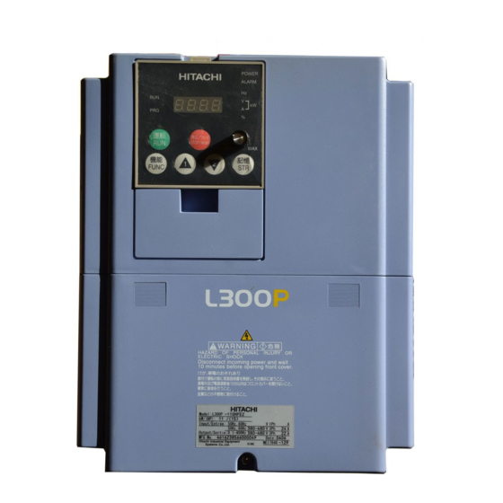
1. Investigation of the inverter 1.1 Specification label (Model name, Manufacturing number ; MFG) There are 2 specification label attached to the inverter as shown in Fig 1-1. Please confirm the model name and MFG number from the specification label as follows. Model name Applicable motor Input ratings... -
Page 5: Inverter Specification
1.2 Inverter specification 1.2.1 SJ300 Monitor Mode Dis- Function name play code Output frequency d001 monitor Output current d002 monitor Operation direction d003 monitor PID feedback d004 monitor Intelligent input d005 terminal monitor Intelligent output d006 terminal monitor Frequency d007 conversion monitor d012 torque monitor... - Page 6 Function Mode Code Function name A001 Frequency setting selection A002 Operation setting selection A003 Base frequency A203 Base frequency, 2nd motor A303 Base frequency, 3rd motor A004 Maximum frequency A204 Maximum frequency, 2nd motor A304 Maximum frequency, 3rd motor A005 AT terminal selection A006 02 selection...
- Page 7 Function Mode Code Function name A061 frequency maximum limiter A261 frequency maximum limiter A062 frequency minimum limiter A262 frequency minimum limiter A063 Jump frequency1 A064 Jump frequency Width 1 A065 Jump frequency2 A066 Jump frequency Width 2 A067 Jump frequency3 A068 Jump frequency Width 3 A069...
- Page 8 Function mode Code Function name b012 Electronic thermal level Electronic thermal level b212 motor) Electronic thermal level b312 motor) electronic thermal b013 characteristic selection electronic thermal b213 characteristic selection electronic thermal b313 characteristic selection Free electronic thermal b015 frequency 1 Free electronic thermal b016 current 1...
- Page 9 Function mode Code Function name Intelligent input 1 a/b C011 (NO/NC) selection Intelligent input 2 a/b C012 (NO/NC) selection Intelligent input 3 a/b C013 (NO/NC) selection Intelligent input 4 a/b C014 (NO/NC) selection Intelligent input 5 a/b C015 (NO/NC) selection Intelligent input 6 a/b C016 (NO/NC) selection...
- Page 10 Function mode Code Function name b034 RUN time/Power ON time level b035 Operation direction restrict b036 Start reduced voltage 00(Start reduced voltage time small)-06(Start reduced voltage time large) b037 Display selection 00(all display)/01(each function display)/02(User setting / main setting) b040 Torque limit mode selection Torque limit level 1 setting b041...
- Page 11 SJ300 Setting range 00(Invalid)/01( Valid(the motor does not rotate) )/ 02( Valid(the motor rotates)) 00(Hitachi general purpose motor data)/01( Autotuning data) / 02( Autotuning data with online autotuning) 00(Hitachi general purpose motor data)/01( Autotuning data) / 02( Autotuning data with online autotuning) 0.20-75.0(kW) <0.2-160(kW)>...
- Page 12 Function mode Code Function name Option1 operation selection P001 on error Option2 operation selection P002 on error P010 Feed-back option selection Encoder pulse number P011 setting P012 Control mode selection Pulse train input mode P013 selection Orientation stop position P014 setting P015 Orientation speed setting...
-
Page 13: L300P
1.2.2 L300P Monitor code Dis- Function name play code Output frequency d001 monitor Output current d002 monitor Operation direction d003 monitor PID feedback d004 monitor Intelligent input d005 terminal monitor Intelligent output d006 terminal monitor Frequency d007 conversion monitor Output voltage d013 monitor Electric power... - Page 14 Function Mode Code Function name A001 Frequency setting selection A002 Operation setting selection A003 Base frequency A203 Base frequency, 2nd motor A004 Maximum frequency Maximum frequency, 2nd A204 motor A005 AT terminal selection A006 02 selection A011 0 start A012 0 end A013 0 start rate...
- Page 15 Function Mode Code Function name A061 frequency upper limiter A261 frequency upper limiter A062 frequency lower limiter A262 frequency lower limiter A063 Jump frequency1 A064 Jump frequency Width 1 A065 Jump frequency2 A066 Jump frequency Width 2 A067 Jump frequency3 A068 Jump frequency Width 3 A069...
- Page 16 Function Mode Code Function name Overload restriction 00(invalid)/01(enabled on acceleration / constant speed)/02(enabled b021 selection b022 Overload restriction level Overload restriction limit b023 constant Overload restriction 2 00(invalid)/01(valid on acceleration / constant speed)/02(valid on b024 selection b025 Overload restriction level 2 Overload restriction b026 constant 2...
- Page 17 Function Mode Code Function name C070 Data command Communicating C071 transmission speed C072 Communication code C073 Communication bit C074 Communication parity C075 Communication stop bit Communication waiting C078 time C081 O adjustment C082 OI adjustment C083 O2 adjustment C085 Thermistor adjustment C086 AM offset adjustment C087...
- Page 18 Function Mode Code Function name U001 User1 selection U002 User2 selection U003 User3 selection U004 User4 selection U005 User5 selection U006 User6 selection U007 User7 selection U008 User8 selection U009 User9 selection U010 User10 selection U011 User11 selection U012 User12 selection (Note) <...
-
Page 19: Trouble Shooting
2. TROUBLE SHOOTING 2.1 Inverter trip contents, remedy, advice Trip It’s one of INV failure by locked motor, fast ACC/DEC because big current will be flown. By over current detection, INV will shut the output by the hardware. This detection will be done by AC Over current detection at Over current will be detected about output stage... - Page 20 Trip If Instant power failure 15ms or more happened, INV will shut the output. If the instant power failure is longer Instant power failure than preset allowable time or affordable control supply voltage time, INV will work as normal power off. This detection means INV will re-start with the run command after the long instant power failure.
-
Page 21: Option Error
2.2 Option error 2.2.1 Feed-back board (SJ-FB) Trip ü Wire break and/or loose connection of the encoder signal. ü Encoder failure or used the encoder which is not line driver Encorder wire cut output. ü Used encoder without Z phase signal. Detect when the motor rotation exceeds Over speed (Maximum frequency) -
Page 22: Check Of The Trip Monitor Contents
2.3 Check of the trip monitor contents (2) Output frequency at trip (Hz) (3) Output current at trip (A) (4) DC bus voltage at trip (V) (5) Accumulated running time until tripping (h) (6) Accumulated power ON time until tripping (h) (1) Trip cause / Display explanation Trip cause. - Page 23 2.4 Check of the warning monitor contents Warning message is come out when there is any contradiction. Program lamp “PRG” is turned ON while warning (until the data are corrected). Warning message and automatic rewriting Warning 001/ 201 Frequency upper limiter A061/A261 002/ 202 Frequency lower limiter A062/A262 004/ 204...
-
Page 24: Return To An Initialization Setup (Factory-Shipment State)
Initial data b085 selection (The initialization method) Please initialize by the following methods after setting up the above and a setting item. POWER HITACHI ALARM 運転 停止/リセット STOP/RESET 記憶 機能 FUNC (1) Where a function key, a rise key, and a down key are pushed simultaneously, please push stop/reset key. -
Page 25: Debug Mode
( DC bus voltage monitor (V)): Monitor of the DC bus voltage (VPN) of the inverter. d103 ( BRD ON monitor (s)): There is an integrated BRD circuit on 11kW and less for SJ300, and 15kW and less for L300P series. You can find accumulated turning ON time for the integrated BRD transistor. -
Page 26: Function Mode
3.2 Function mode Inverter (logic board) settings can be done as follows. Functional For factory adjustment (change prohibition) C170 to C194 Inverter area code selection Inverter capacity code selection Inverter voltage class code selection Inverter mode change selection Be sure to perform initialization according to the instruction manual after change the data above. Parameter b085 is prior to C195. - Page 27 3.3 A setup of an inverter The logic board of 55 or less kW’s is common by each capacity (0.4-55kW) and the voltage class (200/400V). Please check that name plate of logic is after SJ300P-L K. However, it is necessary to unite with an inverter main part and to set up a logic board. 3.3.1 Setting procedure (1) Preparation before switching on a power supply (1)-1 Please connect a digital operator.
- Page 28 (2) A setup of output capacity is checked. (The check method) Please display H003, push FUNC key and check that it is ***. * Please check having become as shown in H003 of Table 1 and Table 2 about a display of the portion of ***. (3) Model selection of Sj300 /L300P is checked.
-
Page 29: The Check Of Control Power Supply Voltage And A Control Signal
4. The check of control power supply voltage and a control signal 4.1 Control power supply Item Tolerance level PV5 +5V power supply PV12 +12V power supply NV12 -12V power supply -13.2V - -10.8V PV24 24V power supply 4.2 Control signal Signal Measurement place J1 connector 12pin-L... -
Page 30: Maintenance And Inspection
5.1.3 Periodical inspection Check the portions where the inverter must not be in operation. Please contact HITACHI for a periodical inspection. (1) Is there any abnormality in cooling? ---- Cleaning of air filter. (2) Tightening check and additional tightening. ---- Loose tightening of the screws and bolts could occur (3) Isn’t there any corrosion or damage in the conductors? -
Page 31: Daily And Annual Maintenance
5.2 Daily and annual maintenance Item Ambient humidity, dust, corrosive gas, oil Environment Devices overall Power supply voltage Overall Check installation for looseness. Conductors / cables Terminal block Inverter / Converter DC bus capacitor Check for stuttering noise during Relay, contactor Resistors Cooling fan Check the balance of the output... -
Page 32: Megger Test
5.3 Megger test Disconnect all the wiring in case of megger test on external circuit, so that no test voltage is supplied to the inverter. Use tester (high resistance range) for the test of control circuit. Do not use megger nor buzzer. Megger test should be done only on the power (mains) portions. - Page 33 5.5 How to check inverter & converter portion Inverter and converter module can be checked by using a tester. (Preparation) (1)Disconnect all the connected wires and devices to the power terminals (R, S, T, U, V, W, P and RB). (2)Tester is to be set as 1ohm range.
-
Page 34: Parts Replacement
Inverter is consists from many electrical components. And inverter cannot work properly unless all of them works normal. Electrical components in following table are the components which may degrade according to the usage period. HITACHI recommend to replace those electrical components periodically to avoid any expected failure caused by them. Parts name Recommended... - Page 35 (How to remove cooling fan for steel case) • Remove terminal cover ‚ Reconfirm that the charge lamp is turned OFF. ƒ Remove the all screws of the cooling fan case and pull out like following figure. „ Remove the connector for fan connection. (How to fix cooling fan for steel case) •...
- Page 36 (How to fix DC bus capacitors for mold case) • Put capacitor PCB onto the capacitor holder plate and put insulation sheet on it. ‚ Insert capacitor holder plate sliding along the ditch. ƒ Fix the capacitor PCB with screws. „...
-
Page 37: Unit Replacement
5.7 Unit replacement Unit replacement can be done without rewiring of the logic signal. (How to exchange) • Remove terminal cover. ‚ Reconfirm that the charge lamp is turned OFF. ƒ Remove the screws, right and left portion , like following figure. „... - Page 38 English CB circuit / DC bus capacitor circuit CB board / DC bus capacitor board Instantaneous power failure detection Phase failure detection Opt coupler / Photo coupler Reference voltage Inrush current limiting (circuit) Thyrister drive circuit (Suppressing circuit) Power supply for Thyrister gate Control signal for Thyrister BRD drive circuit (incl.
- Page 39 Internal block diagram...
- Page 40 SJ300-004-007LF Circuit Diagram H I T A C H I PLUG Digital Operator Plug STOP/RESE FUNC SP SN RP SN P24 PLC Bus Capacitor Board OPEC CM1 11 12 13 14 15 CM2 H O 1 CM1 FM TH Main Board Flat Cable OPTXC OPT1C...
- Page 41 SJ300-015 - 055LF Circuit Diagram H I T A C H I PLUG Digital Operator Plug STOP/RESE FUNC SP SN RP SN P24 PLC Bus Capacitor Board OPEC 1 CM1 CM1 11 12 13 14 15 CM2 H O Main Board Flat Cable OPT1C OPTXC...
- Page 42 SJ300-075-110LF , L300P-110-150LFR Circuit Diagram H I T A C H I PLUG Digital operator Plug STOP/RESE FUNC SP SN RP SN P24 PLC Bus Capacitor Board OPEC 1 CM1 CM1 11 12 13 14 15 CM2 H Main Board Flat Cable OPT1C OPTXC...
- Page 43 SJ300-150 - 220LF , L300P-185 - 300LFR Circuit Diagram DM Board Control Power Board H I T A C H I FUNC SP SN RP SN P24 PLC PLUG OPEC Digital Operator STOP/RESE Plug CM1 11 12 13 14 15 CM2 H O 1 CM1 IGBT Main Board...
- Page 44 SJ300-300LF, L300P-370LFR Circuit Diagram DM Board Control Power Board FUNC Pre Control Power Board SP SN RP SN FW 8 P24 PLC H I T A C H I PLUG OPEC Digital Operator STOP/RESE Plug FM TH CM1 11 IGBT CT Board Main Board Flat Cable...
- Page 45 SJ300-370-450LF, L300P-450-550LFR Circuit Diagram DM Board Control Power Board Pre Control FUNC Power Board SP SN RP SN P24 PLC H I T A C H I PLUG OPEC Digital Operator STOP/RESE Plug FM TH CM1 11 IGBT CT Board Main board Flat Cable OPT1C...
- Page 46 SJ300-550LF,L300P-750LFR Circuit Diagram DM Board Control Power Board Pre Control FUNC Power Board SP SN RP SN P24 PLC H I T A C H I PLUG OPEC Digital Operator STOP/RESE Plug FM TH CM1 11 12 13 14 15 R1-R6 IGBT CT Board...
- Page 47 SJ300-007HF Circuit Diagram POWE H I T A C H I ALAR PLUG Digital Operator Plug STOP/RESE FUNC SP SN RP SN FW 8 7 P24 PLC Bus Capacitor Board OPEC CM1 11 12 13 14 15 CM2 H O 3 2 1 CM1 Main Board Flat Cable...
- Page 48 SJ300-015-055HF Circuit Diagram H I T A C H I PLUG Digital Operator Plug STOP/RESE FUNC SP SN RP SN P24 PLC Bus Capacitor Board OPEC CM1 11 12 13 14 15 CM2 H O 1 CM1 Min Board Flat cable OPT1C OPTXC Option Board...
- Page 49 SJ300-075-110HF , L300P-110-150HFR Circuit Diagram H I T A C H I PLUG Digital operator Plug STOP/RESE FUNC SP SN RP SN P24 PLC Bus Capacitor Board OPEC CM1 11 12 13 14 15 1 CM1 Main Board Flat Cable OPT1C OPTXC Option Board...
- Page 50 SJ300-150 - 220HF , L300P-185 - 300HFR Circuit Diagram DM Board Control Power Board H I T A C H I FUNC SP SN RP SN P24 PLC PLUG OPEC Digital Operator Plug STOP/RESE 1 CM1 FM TH CM1 11 12 13 14 15 CM2 H O IGBT Main Board OPT1C...
- Page 51 SJ300-300HF , L300P-370HFR Circuit Diagram DM Board Control Power Board H I T A C H I FUNC Pre Control Power Board SP SN RP SN P24 PLC PLUG OPEC Digital Operator Plug STOP/RESE 1 CM1 FM TH CM1 11 12 13 14 15 CM2 H O IGBT CT Board Main Board...
- Page 52 SJ300-370- 550HF,L300P-450-750HFR Circuit Diagram DM Board Control Power Board H I T A C H I Control FUNC Power Board SP SN RP SN FW 8 P24 PLC PLUG OPEC Digital Operator Plug STOP/RESE 1 CM1 FM TH CM1 11 12 13 14 15 IGBT CT Board Main board...
- Page 53 SJ300-750-1320HF , L300P-900-1320HFR Circuit Diagram DM Board Control Power Board Pre Control FUNC Power Board SP SN RP SN P24 PLC Main Board H I T A C H I PLUG OPEC Digital Operator STOP/RESE Plug CM1 11 1 CM1 FM TH Driver Board R1-R6...
- Page 72 SJ300/L300P Series SPARE PARTS LIST Parts No. Drawing No. Description Remarks 255023 3T017245-1 DC Bus Capacitor 1500uF DC Bus Capacitor 1800uF 255024 3T017245-2 255025 3T017245-3 DC Bus Capacitor 2200uF 255026 3T017997-1 DC Bus Capacitor 3300uF 255027 3T017997-2 DC Bus Capacitor...
- Page 73 SJ300/L300P Series SPARE PARTS LIST Parts No. Drawing No. Description Remarks 254501 4T016894-1A Terminals Cover 19-3 254502 4T016895-1A Terminals Cover 19-3 254503 4T016894-1B Terminals Cover 19-3 254504 4T016895-1B Terminals Cover 19-3 254814 3T016788-1 Spacer Cover 19-5 254815 3T016788-2 Spacer Cover...
- Page 74 SJ300/L300P Series SPARE PARTS LIST Parts No. Drawing No. Description Remarks 254985 SJ3 B075L Main PCB with Main body case 255103 SJ3 B110L Main PCB with Main body case 255104 SJ3 B150L Main PCB 255105 SJ3 B185L Main PCB 255106...
- Page 75 SJ300/L300P Series SPARE PARTS LIST Parts No. Drawing No. Description Remarks 255084 SJ3 C15L DM PCB 255085 SJ3 C18-30L DM PCB 255086 SJ3 C37-45L DM PCB 255087 SJ3 C55-90L DM PCB 255088 SJ3 C15-30H DM PCB 255089 SJ3 C37-55H DM PCB...
- Page 76 SJ300/L300P Series SPARE PARTS LIST Parts No. Drawing No. Description Remarks 254801 NGMB25 Rubber Bush 254802 NGMB31 Rubber Bush 254803 NGMB39 Rubber Bush 254802 NGMB31 Rubber Bush 254804 NGMB51 Rubber Bush 254804 NGMB51 Rubber Bush 255125 N04RC1610-10 Ferrite core for J51...
Need help?
Do you have a question about the L300P Series and is the answer not in the manual?
Questions and answers