Table of Contents
Advertisement
Quick Links
Advertisement
Chapters
Table of Contents

Subscribe to Our Youtube Channel
Related Manuals for Asus PE100A


Summary of Contents for Asus PE100A
- Page 1 PE100A Embedded Computer User Manual...
- Page 2 Copyright © 2022 ASUSTeK COMPUTER INC. All Rights Reserved. LIMITATION OF LIABILITY Circumstances may arise where because of a default on ASUS’ part or other liability, you are entitled to recover damages from ASUS. In each such instance, regardless of the basis on which you are entitled to claim damages from ASUS, ASUS is liable for no more than damages for bodily injury (including death) and damage to real property and tangible personal property;...
-
Page 3: Table Of Contents
3.6 Installing an SD card (Top side) ................41 3.7 Installing a wireless card to the M.2 slot (Top side) ........42 3.8 Installing an mPCIe / mSATA module (Bottom side) ........44 3.9 Installing antennas (optional) ................47 3.10 Installing the wall mount ..................53 PE100A... - Page 4 3.12 Installing the terminal block (optional) ............55 Chapter 4: Setting up your Embedded Computer 4.1 Requirements ......................58 4.2 Flashing the OS Image ..................58 Appendix Safety information ......................62 Setting up your system ......................62 Care during use ........................... 63 Regulatory notices ......................65 Service and Support ......................78 PE100A...
-
Page 5: About This Manual
/ solid state drive of your Embedded Computer. Chapter 4: Setting up your Embedded Computer This chapter will guide you in setting up your Embedded Computer for the first time. Appendix This section includes notices and safety statements your Embedded Computer. PE100A... -
Page 6: Conventions Used In This Manual
NOTE: This message contains additional information and tips that can help complete tasks. WARNING! This message contains important information that must be followed to keep you safe while performing certain tasks and prevent damage to your Embedded Computer's data and components. PE100A... -
Page 7: Package Contents
Package contents Your Embedded Computer package contains the following items: PE100A AC power adapter* Power cord* Terminal blocks Terminal block power adapter I/O port dust covers Wall mount kit PE100A... - Page 8 • If the device or its components fail or malfunction during normal and proper use within the warranty period, bring the warranty card to the ASUS Service Center for replacement of the defective components. PE100A...
-
Page 9: Chapter 1: Getting To Know Your Embedded Computer
Getting to know your Embedded Computer... -
Page 10: Features
NOTE: The LTE wireless antenna is optional and may not come bundled. GPS Wireless antenna jack The GPS wireless antenna jack allows you to connect a wireless antenna for GPS signals. NOTE: The GPS wireless antenna is optional and may not come bundled. PE100A... - Page 11 Activity Link LED Speed LED Status Description Status Description No link 10 Mbps connection Yellow Linked Orange 100 Mbps connection Yellow (blinking) Data activity Green 1 Gbps connection Yellow (blinking then Ready to wake steady) up from suspend mode PE100A...
- Page 12 Power button The power button allows you to turn the Embedded Computer on or off. You can use the power button to put your Embedded Computer to sleep mode or press it for ten (10) seconds to force shutdown. PE100A...
-
Page 13: Rear View
RS485 RS422 RS232 RS485 RS232 RS485 RS422 1 2 3 4 5 1 2 3 4 5 6 7 8 9 10 RS422 RS422 6 7 8 9 10 1 2 3 4 5 1 2 3 4 5 PE100A... - Page 14 Embedded Computer. WARNING! The power adapter may become warm to hot when in use. Do not cover the adapter and keep it away from your body. Functional Earth Ground The Functional Earth Ground provides you with a grounding point. PE100A...
-
Page 15: Motherboard Overview
Motherboard Overview 1.2.1 Motherboard layout The PE100A is an Embedded Computer based on a Pico-ITX motherboard and is supported by a secondary I/O board for extra functionality. Refer to the table for the page numbers of the numbered items. Pico-ITX motherboard... - Page 16 Secondary I/O board PE100A...
- Page 17 Pico-ITX motherboard Boot Mode switch M.2 Wi-Fi slot Micro SD card slot I2C connector SPI TPM connector RTC Battery connector IO Board-to-Board connector Secondary I/O board IO board switch mPCIe / mSATA slot Motherboard Board-to-Board connector Nano SIM Card slot PE100A...
-
Page 18: Pico-Itx Motherboard
The Boot Mode switch allows you to configure between different boot modes and the location to boot from. Please refer to the table below for the different boot modes. Boot Mode Boot type Serial Downloader Internal Boot (default) Boot Mode Boot type eMMC (default) PE100A... -
Page 19: Wi-Fi Slot
The M.2 Wi-Fi slot allows you to install an M.2 Wi-Fi module (E-key, type 2230). NOTE: The M.2 Wi-Fi module is purchased separately. Micro SD Card slot The micro SD Card slot allows you to install a micro SD card. NOTE: The micro SD card is purchased separately. PE100A... -
Page 20: I2C Connector
The SPI TPM connector supports a Trusted Platform Module (TPM) system, which can securely store keys, digital certificates, passwords, and data. A TPM system also helps enhance network security, protects digital identities, and ensures platform integrity. Connector type Header 2x7p,K14, 2.0mm pitch PE100A... -
Page 21: Rtc Battery Connector
RTC Battery connector The RTC Battery connector allows you to connect a lithium CMOS battery. PE100A... -
Page 22: Io Board-To-Board Connector
IO Board-to-Board connector The IO Board-to-Board connector allows you to connect the Pico-ITX motherboard and secondary I/O board. PE100A... -
Page 23: Secondary I/O Board
Refer to the tables below for the different switch configurations. mPCIe / mSATA Terminator Output type mPCIe (default) OFF (default) mSATA Terminator Output type RS-232 (default) CAN Bus Terminator Output type RS-232 (default) RS-422 RS-485 PE100A... -
Page 24: Mpcie / Msata Slot
The mPCIe/mSATA slot allows you to install an mPCIe peripheral device or an mSATA peripheral device. The default setting for the slot is mPCIe. To switch to mSATA, please refer to IO board switch. NOTE: The mPCIe / mSATA peripheral device is purchased separately. PE100A... -
Page 25: Motherboard Board-To-Board Connector
Motherboard Board-to-Board connector The Motherboard Board-to-Board connector allows you to connect the Pico-ITX motherboard and secondary I/O board. PE100A... -
Page 26: Nano Sim Card Slot
Nano SIM Card slot The nano SIM card slot allows you to install a nano SIM card. NOTE: The nano SIM card is purchased separately. PE100A... -
Page 27: Chapter 2: Using Your Embedded Computer
Using your Embedded Computer... -
Page 28: Getting Started
Connect the 2-pin terminal block DC power connector into your Embedded Computer’s power (DC) input. Plug the AC power adapter into a 100V~240 V power source. NOTE: The power adapter may vary in appearance, depending on model and your region. PE100A... - Page 29 • Do not disable or remove the power cord grounding plug, the grounding is an important safety feature. • Ensure to plug the power cord into a grounded (earthed) electrical outlet that is easily accessible at all times. PE100A...
-
Page 30: Connect A Display Panel To Your Embedded Computer
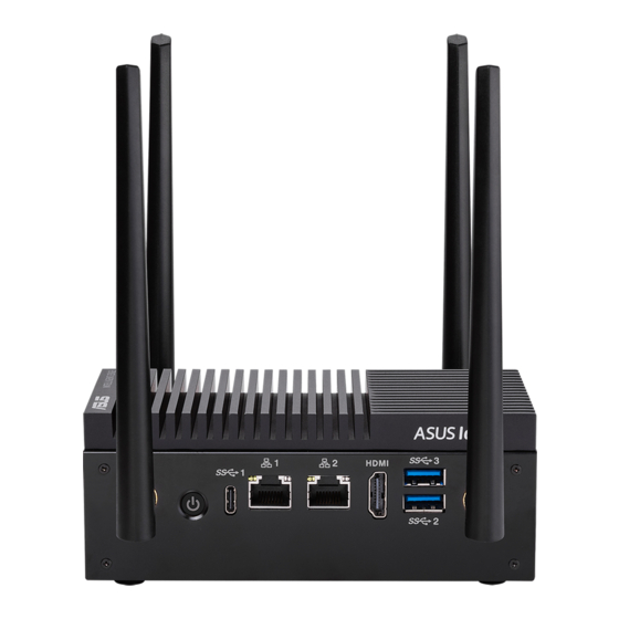
HDMI™ connector To connect a display panel to your Embedded Computer: Connect one end of an HDMI™ cable to an external display, and the other end of the cable to your Embedded Computer’s HDMI™ port. Connect display via HDMI™ port PE100A... -
Page 31: Connect The Usb Cable From Keyboard Or Mouse
To connect a keyboard and mouse to your Embedded Computer: Connect the USB cable from your keyboard and mouse to any of the USB ports of your Embedded Computer. NOTE: • The keyboard varies with country and/or region. • The keyboard and mouse are purchased separately. PE100A... -
Page 32: Turn On Your Embedded Computer
2.1.4 Turn on your Embedded Computer Press the power button to turn on your Embedded Computer. NOTE: The Embedded Computer will power on automatically the first time it is connected to a power source. PE100A... -
Page 33: Turning Off Your Embedded Computer
Turning off your Embedded Computer If your Embedded Computer is unresponsive, press and hold the power button for at least ten (10) seconds until your Embedded Computer turns off. PE100A... - Page 34 PE100A...
-
Page 35: Chapter 3: Upgrading Your Embedded Computer
Upgrading your Embedded Computer... -
Page 36: Removing The Bottom Cover
Turn off your Embedded Computer, and then disconnect all cables and peripherals. Place the Embedded Computer on a flat stable surface with its top side facing down. Remove the screw from the bottom cover (A), then remove the bottom cover (B). PE100A... -
Page 37: Replacing The Bottom Cover
Replacing the bottom cover Align the bottom cover latches with the latch holes on the bottom of your Embedded Computer. Secure the bottom cover using the screw removed previously. PE100A... -
Page 38: Removing The Top Cover
Removing the top cover Turn off your Embedded Computer, and then disconnect all cables and peripherals. Remove the four (4) rubber feet screws from the bottom of the Embedded Computer (A), and then remove the top cover (B). PE100A... -
Page 39: Replacing The Top Cover
Replacing the top cover Place the top cover into the Embedded Computer chassis and ensure the ASUS IoT logo is on the left side of the top cover when you are facing the front of the Embedded Computer. IMPORTANT! Ensure that the RF cables and/or other cables are not under or in the way of the top cover when installing it, as this may cause the antennas to not work properly. -
Page 40: Installing A Nano Sim Card (Front Panel)
NOTE: This Nano SIM slot is hot swappable. Remove the two (2) screws securing the Nano SIM card slot cover, and then remove the cover. Insert the nano SIM card into the slot. Replace slot cover and secure it with the screws removed previously. PE100A... -
Page 41: Installing An Sd Card (Top Side)
Installing an SD card (Top side) Insert your SD card into the SD card slot. Ensure that the SD card is pushed all the way into the SD card slot. PE100A... -
Page 42: Installing A Wireless Card To The M.2 Slot (Top Side)
Please refer to the Installing antennas section for more • information on installing the antennas. • Connecting antennas to your wireless card may strengthen the wireless signal. • A soft clicking sound indicates that the antenna has been securely attached on the wireless card. PE100A... - Page 43 WIFI-Aux (DIV) WIFI-Main WIFI-Aux (DIV) WIFI-Main Antenna Color Coding Band Color Antenna Type Black WIFI-Aux (DIV) Black WIFI-Main PE100A...
-
Page 44: Installing An Mpcie / Msata Module (Bottom Side)
Refer to Installing antennas for more information on installing the • antennas. • Connecting antennas to your LTE module may strengthen the signal. • A soft clicking sound indicates that the antenna has been securely attached on the LTE module. PE100A... - Page 45 Antenna Color Coding Band Color Antenna Type White LTE-Aux (DIV) Blue LTE-Main PE100A...
- Page 46 Press down, and then secure it in place using the two (2) screws bundled with the module. To install an mSATA storage module: Align and insert the mSATA storage module into the slot. Press down, and then secure it in place using the two (2) screws bundled with the module. PE100A...
-
Page 47: Installing Antennas (Optional)
(see below diagram). • LTE antennas are flatter and slightly longer than the Wi-Fi and GPS antennas. • GPS antennas look the same as Wi-Fi antennas but are clearly labeled as GPS. Antenna jack locations Wi-Fi PE100A... - Page 48 Remove the rear panel cover by removing the four (4) screws from the cover. Prepare the RF connector and cable. Remove the rubber caps from the antenna holes. Insert the antenna jack end of the RF connector and cable into the antenna jack from within the chassis outwards. PE100A...
- Page 49 Replace the top cover. Refer to Replacing the top cover for details. Screw the external Wi-Fi antennas onto their corresponding antenna jacks on the rear panel by turning them in a clockwise direction. 10. Position the antennas for optimal signal reception. PE100A...
- Page 50 Insert the bundled O-rings over the antenna jacks, and then secure the antenna jacks using the bundled hex screws. Thread the cables from both sides of the motherboard to the bottom of the device. PE100A...
- Page 51 Connect the other end of the RF connectors and cables to your WLAN card. Refer to Installing an mPCIe module to the Mini PCIe/mSATA slot (Bottom side) for details. PE100A...
- Page 52 Replacing the bottom cover for details. 10. Screw the external LTE and GPS antennas onto their corresponding antenna jacks on the front panel by turning them in a clockwise direction. 11. Position the antennas for optimal signal reception. PE100A...
-
Page 53: Installing The Wall Mount
Align the wall mount with the rubber feet screw holes, then remove the rubber feet from the rubber feet screws and secure the wall mount to your Embedded Computer using the rubber feet screws. NOTE: The rubber feet screws and wall mount screws are the same screws. PE100A... -
Page 54: Installing Din Rail Clips (Optional)
Secure the DIN rail clips to the wall mount using the screws bundled with the DIN rail clips. Clip the final assembly to a DIN rail by hooking the DIN rail clips to the top of the DIN rail and then pressing down until you hear the clips snap into place. PE100A... -
Page 55: Installing The Terminal Block (Optional)
• The terminal block is purchased separately. Please refer to Rear view for the location and pin definitions of the • Serial (COM) terminal connector and Isolated DIO connector. Installing a terminal block to the Serial (COM) terminal connector PE100A... - Page 56 Installing a terminal block to the Isolated DIO connector PE100A...
-
Page 57: Chapter 4: Setting Up Your Embedded Computer
Setting up your Embedded Computer PE100A... -
Page 58: Requirements
Embedded Computer to your computer are all disconnected. The Boot Mode switch is set to eMMC mode, refer to Boot Mode • switch under the Pico-ITX motherboard section for more information on setting the Boot Mode switch. PE100A... - Page 59 Executing the flash script: Download the OS image from the ASUS website, and then unzip the image file. Run the flash script or command file to start the flash process. The flash process should take a few minutes.
- Page 60 PE100A...
-
Page 61: Appendix
Appendix... -
Page 62: Safety Information
– access is through the use of a TOOL or lock and key, or other means of security, and is controlled by the authority responsible for the location. • This device shall not be connected to an Ethernet network with outside plant routing. PE100A... -
Page 63: Care During Use
CAUTION: Danger of explosion if battery is incorrectly replaced. Replace only with the same or equivalent type recommended by the manufacturer. Dispose of used batteries according to the manufacturer’s instructions. NO DISASSEMBLY The warranty does not apply to the products that have been disassembled by users PE100A... - Page 64 This symbol of the crossed out wheeled bin indicates that the product (electrical, electronic equipment, and mercury- containing button cell battery) should not be placed in municipal waste. Check local technical support services for product recycling. PE100A...
-
Page 65: Regulatory Notices
IMPORTANT! Outdoor operations in the 5.15~5.25 GHz band is prohibited. This device has no Ad-hoc capability for 5250~5350 and 5470~5725 MHz. CAUTION! Any changes or modifications not expressly approved by the grantee of this device could void the user’s authority to operate the equipment. PE100A... - Page 66 RF exposure compliance. Operation is subject to the following two conditions: • This device may not cause interference and • This device must accept any interference, including interference that may cause undesired operation of the device. PE100A...
- Page 67 Ch01 through CH11 Japan 2.412-2.484 GHz Ch01 through Ch14 Europe ETSI 2.412-2.472 GHz Ch01 through Ch13 KC: Korea Warning Statement Class A: 사용자 안내문 이 기기는 업무용 환경에서 사용할 목적으로 적합성평가를 받은 기기로서 가정용 환경에서 사용하는 경우 전파간섭의 우려가 있습니다. PE100A...
- Page 68 Class A ITE Japan RF Equipment Statement 屋外での使用について 本製品は、 5GHz帯域での通信に対応しています。 電波法の定めにより 5.2GHz、 5.3GHz帯域の電波は屋外で使用が禁じられています。 法律および規制遵守 本製品は電波法及びこれに基づく命令の定めるところに従い使用してくだ さい。 日本国外では、 その国の法律または規制により、 本製品の使用ができ ないことがあります。 このような国では、 本製品を運用した結果、 罰せられる ことがありますが、 当社は一切責任を負いかねますのでご了承ください。 Japan JATE 本製品は電気通信事業者 (移動通信会社、 固定通信会社、 インターネッ ト プロバイダ等) の通信回線 (公衆無線LANを含む) に直接接続することがで きません。 本製品をインターネッ トに接続する場合は、 必ずルーター等を 経由し接続してください。 PE100A...
- Page 69 ASUS products sold in Vietnam, on or after September 23, 2011,meet the requirements of the Vietnam Circular 30/2011/TT-BCT. Các sản phẩm ASUS bán tại Việt Nam, vào ngày 23 tháng 9 năm2011 trở về sau, đều phải đáp ứng các yêu cầu của Thông tư 30/2011/TT-BCT của Việt Nam.
- Page 70 Turkey RoHS AEEE Yönetmeliğine Uygundur ASUS Recycling/Takeback Services ASUS recycling and takeback programs come from our commitment to the highest standards for protecting our environment. We believe in providing solutions for you to be able to responsibly recycle our products, batteries, other components as well as the packaging materials.
- Page 71 備考 1.“ ○”係指該項限用物質之百分比含量未超出百分比含量基準值。 備考 2.“-”係指該項限用物質為排除項目。 Note 1 “○“ indicates that the percentage content of the restricted substance does not exceed the percentage of reference value of presence. Note 2 The “-“ indicates that the restricted substance corresponds to the exemption. PE100A...
- Page 72 All ASUS products with the ENERGY STAR logo comply with the ENERGY STAR standard, and the power management feature is enabled by default. The monitor is automatically set to sleep within 10 minutes of user inactivity;...
- Page 73 824 - 849 MHz 25.0 dBm 2500 - 2570 MHz 25.0 dBm 880 - 915 MHz 25.0 dBm 832 - 862 MHz 25.0 dBm 703 - 748 MHz 25.0 dBm 2570 - 2620 MHz 25.0 dBm 2300 - 2400 MHz 25.0 dBm PE100A...
- Page 74 ASUSTek Computer Inc. hereby declares that this device is in compliance with the essential requirements and other relevant provisions of Directive 2014/53/EU. Full text of EU declaration of conformity is available at https://www.asus.com/support/ The WiFi operating in the band 5150-5350MHz shall be restricted to indoor use for countries listed in the table below: Déclaration simplifiée de conformité...
- Page 75 Společnost ASUSTek Computer Inc. tímto prohlašuje, že toto zařízení splňuje základní požadavky a další příslušná ustanovení směrnice 2014/53/ EU. Plné znění prohlášení o shodě EU je k dispozici na adrese https://www.asus.com/support/ V zemích uvedených v tabulce je provoz sítě Wi-Fi ve frekvenčním rozsahu 5 150 - 5 350 MHz povolen pouze ve vnitřních prostorech: Forenklet EU-overensstemmelseserklæring...
- Page 76 Declaración de conformidad simplificada para la UE Por la presente, ASUSTek Computer Inc. declara que este dispositivo cumple los requisitos básicos y otras disposiciones pertinentes de la directiva 2014/53/EU. En https://www.asus.com/support/ está disponible el texto completo de la declaración de conformidad para la UE.
- Page 77 ต้ ้องการที่่ � จำ ำ า เป็ นแล้ะเง่ � อ นไขที่่ � เ ก่ � ย ว่ข ้องอ่ � น ๆ ของบที่บั ญ ญั ต้ ิ ข ้อกำ า หนด 2014/53/EU เน่ � อ หาที่่ � ส มีบู ร ณ์์ ข องประกาศคว่ามี สอดคล้ ้องกั บ EU มี่ อ ยู ่ ที่ ่ � https://www.asus.com/support/ การที่ำ...
-
Page 78: Service And Support
880 - 915 MHz 25.0 dBm 832 - 862 MHz 25.0 dBm 703 - 748 MHz 25.0 dBm 2570 - 2620 MHz 25.0 dBm 2300 - 2400 MHz 25.0 dBm Service and Support Visit our multi-language website at https://www.asus.com/support/. PE100A... - Page 79 1F., No. 15, Lide Rd., Beitou Dist., Taipei City 112, Taiwan Authorised ASUSTeK Computer GmbH representative in Address: Harkortstrasse 21-23, 40880 Ratingen, Germany Europe Authorized ASUSTEK (UK) LIMITED Representative in 1st Floor, Sackville House, 143-149 Fenchurch Street, London, United Kingdom EC3M 6BL, England, United Kingdom PE100A...
- Page 80 PE100A...
Need help?
Do you have a question about the PE100A and is the answer not in the manual?
Questions and answers