Table of Contents
Advertisement
Advertisement
Table of Contents

Related Manuals for Asus P1-P5945GC


Summary of Contents for Asus P1-P5945GC
-
Page 1: User Guide
P1/P2-P5945GC ASUS PC (Desktop Barebone) User Guide... - Page 2 Product warranty or service will not be extended if: (1) the product is repaired, modified or altered, unless such repair, modification of alteration is authorized in writing by ASUS; or (2) the serial number of the product is defaced or missing.
-
Page 3: Table Of Contents
Table of contents Notices ... vi Safety information ...vii About this guide ...viii System package contents ... x Chapter 1: System Introduction Welcome! ... 1-2 Front panel ... 1-2 Rear panel ... 1-4 Internal components ... 1-6 Chapter 2: Basic Installation Preparation ... - Page 4 Motherboard layout ... 4-2 Jumpers ... 4-3 Connectors ... 4-5 Chapter 5: BIOS Information Managing and updating your BIOS ... 5-2 5.1.1 ASUS EZ Flash 2 utility ... 5-2 5.1.2 AFUDOS utility ... 5-3 5.1.3 ASUS CrashFree BIOS 2 utility ... 5-5 5.1.4 ASUS Update utility ...
- Page 5 Table of contents Main menu ... 5-13 5.3.1 System Time ... 5-13 System Date ... 5-13 5.3.2 5.3.3 Primary and Third IDE Master/Slave ... 5-14 5.3.4 IDE Configuration ... 5-15 5.3.5 System information... 5-17 Advanced menu ... 5-18 5.4.1 JumperFree Condiguration ... 5-18 5.4.2 USB Configuration ...
-
Page 6: Canadian Department Of Communications Statement
Notices Federal Communications Commission Statement This device complies with Part 15 of the FCC Rules. Operation is subject to the following two conditions: • This device may not cause harmful interference, and • This device must accept any interference received including interference that may cause undesired operation. -
Page 7: Electrical Safety
Safety information Electrical safety • To prevent electrical shock hazard, disconnect the power cable from the electrical outlet before relocating the system. • When adding or removing devices to or from the system, ensure that the power cables for the devices are unplugged before the signal cables are connected. -
Page 8: About This Guide
About this guide Audience This guide provides general information and installation instructions about the ASUS P1/P2-P5945GC system. This guide is intended for experienced users and integrators with hardware knowledge of personal computers. How this guide is organized This guide contains the following parts: Chapter 1: System introduction This chapter gives a general description of the ASUS P1/P2-P5945GC. -
Page 9: Conventions Used In This Guide
Refer to the following sources for additional information and for product and software updates. ASUS Websites The ASUS websites worldwide provide updated information on ASUS hardware and software products. Refer to the ASUS contact information. Optional Documentation Your product package may include optional documentation, such as warranty flyers, that may have been added by your dealer. -
Page 10: System Package Contents
Check your P1/P2-P5945GC system package for the following items. If any of the items is damaged or missing, contact your retailer immediately. Item description ASUS book size barebone system with • ASUS motherboard • 200W power supply unit • PCI riser card •... - Page 11 Chapter 1 This chapter gives a general description of the ASUS P1/P2-P5945GC. The chapter lists the system features including introduction on the front and rear panel, and internal components. ASUS P1/P2-P5945GC...
-
Page 12: Chapter 1: System Introduction
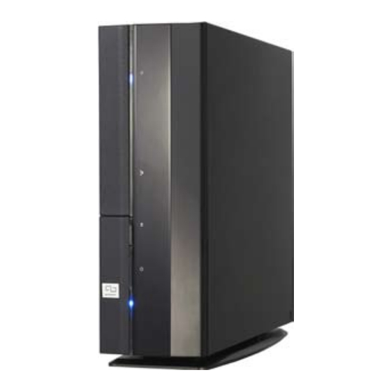
Thank you for choosing the ASUS P1/P2-P5945GC! The ASUS P1/P2-P5945GC is an all-in-one barebone system with a versatile home entertainment feature. The system comes in a stylish mini-tower casing and powered by the ASUS motherboard that supports the Intel Conroe... - Page 13 12. USB 2.0 ports. These Universal Serial Bus 2.0 (USB 2.0) ports are available for connecting USB 2.0 devices such as a mouse, printer, scanner, camera, PDA, and others. 13. Microphone port (pink). This port connects a microphone. 14. Headphone port (lime). This port connects a headphone or a speaker. ASUS P1/P2-P5945GC...
-
Page 14: Rear Panel
Rear panel The system rear panel includes the power connector and several I/O ports that allow convenient connection of devices. Power connector Voltage selector. This switch allows you to adjust the system input voltage according to the voltage supply in your area. If the voltage supply in your area is 100-127V, set this switch to 115V. -
Page 15: Serial Port
Lime Line Out Pink Mic In Gray • Black • Yellow Orange • ASUS P1/P2-P5945GC 4-channel 6-channel Line In Line In Front Speaker Out Front Speaker Out Front Speaker Out Mic In Mic In Rear Speaker Out Rear Speaker Out •... -
Page 16: Internal Components
3.5 inch hard disk drive cage Front panel cover Power supply unit PCI card riser bracket (connected to the motherboard PCI slot) ASUS motherboard DIMM sockets LGA775 socket (under the CPU fan and heatsink assembly) CPU fan and heatsink assembly Chapter 1: System introduction... - Page 17 Chapter 2 This chapter provides step-by-step instructions on how to install components in the system. ASUS P1/P2-P5945GC...
-
Page 18: Preparation
Preparation Before you proceed, make sure that you have all the components you plan to install in the system. Basic components to install 1. Central Processing Unit (CPU) 2. DDR2 Dual Inline Memory Module (DIMM) 3. Expansion card(s) 4. Hard disk drive 5. - Page 19 Pull the cover slightly toward the rear panel. Lift the cover, then set aside. To remove the front panel cover Lift the front panel cover hooks outward. Carefully remove the front panel cover, then set it aside. ASUS P1/P2-P5945GC...
-
Page 20: Central Processing Unit (Cpu)
CPU socket and the socket contacts are not bent. Contact your retailer immediately if the PnP cap is missing, or if you see any damage to the PnP cap/socket contacts/motherboard components. ASUS will shoulder the cost of repair only if the damage is shipment/ transit-related. •... - Page 21 CPU notch. Close the load plate (A), then push the load lever (B) until it snaps into the retention tab. ASUS P1/P2-P5945GC Retention tab Load lever PnP cap Load plate...
-
Page 22: Installing The Cpu Fan And Heatsink Assembly
2.4.4 Removing and Installing the CPU fan and heatsink assembly The system package includes a proprietary CPU fan and heatsink assembly to ensure optimum thermal condition and performance. DO NOT replace the proprietary CPU fan and heatsink with other models! To remove the CPU fan and heatsink assembly: Disconnect the CPU fan cable. -
Page 23: Installing A Dimm
Install only identical (the same type and size) DDR2 memory modules. • Install only ASUS-certified memory modules. Refer to the DDR2 Qualified Vendors List on the next page for details. • Always install DIMMs with the same CAS latency. For optimum compatibility, we recommend that you obtain memory modules from the same vendor. -
Page 24: Qualified Vendors Lists (Qvl)
Qualified Vendors Lists (QVL) DDR2-667 Size Vendor 256MB Kingston KVR667D2N5/256 256MB Kingston KVR667D2N5/256 256MB Kingston KVR667D2N5/256 512MB Kingston KVR667D2N5/512 512MB Kingston KVR667D2N5/512 Kingston KVR667D2N5/1G Kingston KVR667D2N5/1G Kingston KVR667D2N5/1G 512MB Samsung KR M378T6553CZ0-CE6 512MB Samsung KR M378T6453FZ0-CE6 512MB Samsung M378T6553CZ3-CE6 Samsung M378T2953CZ3-CE6 Samsung KR M378T2953CZ0-CE6... -
Page 25: Memory Configuration
CL: CAS Latency DIMM support: Supports one module inserted into either slot, in Single-channel memory configuration. Supports one pair of modules inserted into both slots as one pair of Dual-channel memory configuration. ASUS P1/P2-P5945GC Side(s) Component HYB18T512800AF3733336550 D6408TE7BL-37 K4T56083QF-GCD5 K4T51083QB-GCD5 HYB18T512160AF-3.7AFSS31270... -
Page 26: Installing A Ddr2 Dimm
2.5.2 Installing a DDR2 DIMM Make sure to unplug the power supply before adding or removing DIMMs or other system components. Failure to do so may cause severe damage to both the motherboard and the components. Unlock a DDR2 DIMM socket by pressing the retaining clips outward. -
Page 27: Expansion Slots
Expansion card installation Make sure to unplug the power cord before adding or removing expansion cards. Failure to do so may cause you physical injury and damage motherboard components. Lift the PCI riser card assembly to remove. ASUS P1/P2-P5945GC 2-11... - Page 28 Remove the metal cover opposite the slot that you intend to use. Insert the card connector to the slot, then press the card firmly until it fits in place. Secure the card with a screw. Reinstall the PCI riser card assembly. Make sure that the riser card connector sits properly on the motherboard PCI slot.
-
Page 29: Irq Assignments For This Motherboard
When using PCI cards on shared slots, ensure that the drivers support “Share IRQ” or that the cards do not need IRQ assignments. Otherwise, conflicts will arise between the two PCI groups, making the system unstable and the card inoperable. ASUS P1/P2-P5945GC Standard Function System Timer Keyboard Controller... -
Page 30: Installing An Optical Drive
Installing an optical drive and reinstalling the storage drive assembly Refer to the instructions in this section if you wish to install a new optical drive. Follow these steps to install an optical drive: Turn the storage drive assembly upside down with the 3.5-inch bay on top of the 5.25-inch bay. - Page 31 SATA cable to the SATA HD. Connect the 4-pin power plugs to the power connectors at the back of the drives. Install the storage drive assembly to the chassis. Secure the storage drive assembly with three screws. ASUS P1/P2-P5945GC 2-15...
-
Page 32: Installing The Foot Stand
Installing the foot stand To install the foot stand: Match the foot stand hooks to the holes on the chassis. Pull the foot stand to the direction of the arrow until the lock clicks in place. To remove the foot stand, lift the lock, then slightly push the foot stand to the direction of the rear panel until it disengages from the chassis. -
Page 33: Reinstalling Front Panel Cover
To reinstall the front panel cover: Insert the front panel cover tabs to the holes at the right side of the chassis, then close. Insert the front panel cover hooks to the chassis tabs until the front panel cover fits in place. ASUS P1/P2-P5945GC 2-17... -
Page 34: Reinstalling The Cover
Reinstalling the cover To reinstall the cover: Install the cover to the chassis. Make sure the cover tabs fit the chassis rails. Push the cover toward the front panel until it fits in place. Secure the cover with two screws. 2-18 Chapter 2: Basic installation... - Page 35 Chapter 3 This chapter helps you power up the system and install drivers and utilities from the support CD. ASUS P1/P2-P5945GC...
-
Page 36: Chapter 3: Starting Up
Screen display and driver options may not be the same for different operating system versions. • The contents of the support CD are subject to change at any time without notice. Visit the ASUS website for updates. 2000/XP operating systems ® Press to turn ON the system... -
Page 37: Running The Support Cd
If Autorun is NOT enabled in your computer, browse the contents of the support CD to locate the file ASSETUP.EXE from the BIN folder. Double-click the ASSETUP.EXE to run the CD. ASUS InstAll - Installation Wizard for Drivers Automatically installs all the necessary drivers for this motherboard. Intel(R) Chipset Inf Update Program Installs the Intel(R) Chipset Inf Update Program. -
Page 38: Utilities Menu
This utility helps you keep your computer in healthy operating condition. ASUS Update The ASUS Update utility allows you to update the motherboard BIOS in a Windows environment. This utility requires an Internet connection either through ®... -
Page 39: Asus Contact Information
3.3.3 ASUS Contact information Click the Contact tab to display the ASUS contact information. You can also find this information on the inside front cover of this user guide. ASUS P1/P2-P5945GC... -
Page 40: Software Information
Autorun feature. If Autorun is not enabled in your computer, browse the contents of the support CD to locate the setup.exe file from the ASUS PC Probe II folder. Double-click the setup.exe file to start installation. - Page 41 When displayed, the monitor panel for that sensor also turns red. Refer to the Monitor panels section for details. Preferences You can customize the application using the Preference section in the main window. Click the box before each preference to activate or deactivate. ASUS P1/P2-P5945GC...
-
Page 42: Hardware Monitor Panels
Hardware monitor panels The hardware monitor panels display the current value of a system sensor such as fan rotation, CPU temperature, and voltages. The hardware monitor panels come in two display modes: hexagonal (large) and rectangular (small). When you check the Enable Monitoring Panel option from the Preference section, the monitor panels appear on your computer’s desktop. -
Page 43: Dmi Browser
DMI browser Click to display the DMI (Desktop Management Interface) browser. This browser displays various desktop and system information. Click the plus sign (+) before DMI Information to display the available information. ASUS P1/P2-P5945GC Small display ®... - Page 44 PCI browser Click to display the PCI (Peripheral Component Interconnect) browser. This browser provides information on the PCI devices installed on your system. Click the plus sign (+) before the PCI Information item to display available information. Usage The Usage browser displays real-time information on the CPU, hard disk drive space, and memory usage.
-
Page 45: Configuring Pc Probe Ii
The Preference tab allows you to customize sensor alerts, change temperature scale, or enable the Q-Fan feature. Loads the default threshold values for each sensor Applies your changes ASUS P1/P2-P5945GC Cancels or Loads your saved ignores your configuration changes Saves your... - Page 46 Chapter 4 This chapter gives information about the motherboard that comes with the system. This chapter includes the motherboard layout, jumper settings, and connector locations. ASUS P1/P2-P5945GC...
-
Page 47: Chapter 4: Motherboard Info
Introduction The P1/P2-P5945GC barebone system comes with an ASUS motherboard. This chapter provides technical information about the motherboard for future upgrades or system reconfiguration. Motherboard layout VGA_DVI USBPW34 26.4cm(10.4in) Chapter 4: Motherboard info PRI_IDE USBPW78 SATA1 USB7 CLRTC MS_CON CF_CON... -
Page 48: Jumpers
6. Hold down the <Del> key during the boot process and enter BIOS setup to re-enter data. Clear RTC RAM Except when clearing the RTC RAM, never remove the cap on CLRTC jumper default position. Removing the cap will cause system boot failure. ASUS P1/P2-P5945GC CLRTC Normal Clear RTC (Default) -
Page 49: Usb Device Wake-Up
USB device wake-up (3-pin USBPW12, USBPW34, USBPW78) Set these jumpers to +5V to wake up the computer from S1 sleep mode (CPU stopped, DRAM refreshed, system running in low power mode) using the connected USB devices. Set to +5VSB to wake up from S3 and S4 sleep modes (no power to CPU, DRAM in slow refresh, power supply in reduced power mode). -
Page 50: Serial Ata Connectors
Service Pack1 before using Serial ATA hard disk drives. • When using the connectors in Standard IDE mode, connect the primary (boot) hard disk drive to the SATA1 connector. ASUS P1/P2-P5945GC SATA1 2000 Service Pack 4 or the Windows ®... - Page 51 IDE connectors (40-1 pin PRI_IDE) The onboard IDE connectors are for Ultra DMA 100/66/33 signal cable(s). There are three connectors on each Ultra DMA 100/66/33 signal cable: blue, black, and gray. Connect the blue connector to the motherboard’s IDE connector, then select one of the following modes to configure your device(s).
- Page 52 USB 2.0 specification that supports up to 480 Mbps connection speed. USB7 Connector Never connect a 1394 cable to the USB connectors. Doing so will damage the motherboard! The USB module is purchased separately. ASUS P1/P2-P5945GC CPU_FAN USB7 USB LP7+ USB LP7- USBPW78...
- Page 53 ATX power connectors (24-pin EATXPWR, 4-pin ATX12V) These connectors are for ATX power supply plugs. The plugs from the power supply are designed to fit these connectors in only one orientation. Find the proper orientation and push down firmly until the connectors completely fit.
- Page 54 (S/PDIF) port(s). Connect the S/PDIF module cable to this connector, then install the module to a slot opening at the back of the system chassis. Digital Audio Connector The S/PDIF module is purchased separately. ASUS P1/P2-P5945GC SPDIF_OUT module BACK_AUDIO SPDIF_OUT...
- Page 55 System panel connector (6 pin PANEL) System Panel Connector Refer to the connector description below for details. • System power LED (2-pin PLED) This 2-pin connector is for the system power LED. Connect the chassis power LED cable to this connector. The system power LED lights up when you turn on the system power, and blinks when the system is in sleep mode.
- Page 56 Chapter 5 This chapter tells how to change system settings through the BIOS Setup menus and describes the BIOS parameters.
-
Page 57: Managing And Updating Your Bios
5.1.1 ASUS EZ Flash 2 utility The ASUS EZ Flash 2 feature allows you to update the BIOS without having to go through the long process of booting and using a DOS-based utility. The EZ Flash 2 utility is built-in the BIOS chip so it is accessible by pressing <Alt>... -
Page 58: Afudos Utility
Press <Enter>. The utility copies the current BIOS file to the USB Flash. A:\>afudos /oOLDBIOS1.rom AMI Firmware Update Utility - Version 1.19(ASUS V2.07(03.11.24BB)) Copyright (C) 2002 American Megatrends, Inc. All rights reserved. Reading flash ... done Write to file... ok A:\>... -
Page 59: Updating The Bios File
Updating the BIOS file To update the BIOS file using the AFUDOS utility: Visit the ASUS website (www.asus.com) and download the latest BIOS file for the motherboard. Save the BIOS file to a bootable USB Flash. Write the BIOS filename on a piece of paper. You need to type the exact BIOS filename at the DOS prompt. -
Page 60: Asus Crashfree Bios 2 Utility
5.1.3 ASUS CrashFree BIOS 2 utility The ASUS CrashFree BIOS 2 is an auto recovery tool that allows you to restore the BIOS file when it fails or gets corrupted during the updating process. You can update a corrupted BIOS file using the motherboard support CD, or the USB Flash that contains the updated BIOS file. -
Page 61: Recovering The Bios From The Support Cd
Restart the system after the utility completes the updating process. The recovered BIOS may not be the latest BIOS version for this motherboard. Visit the ASUS website (www.asus.com) to download the latest BIOS file. Chapter 5: BIOS setup... -
Page 62: Asus Update Utility
5.1.4 ASUS Update utility The ASUS Update is a utility that allows you to manage, save, and update the motherboard BIOS in Windows allows you to: • Save the current BIOS file • Download the latest BIOS file from the Internet •... -
Page 63: Updating The Bios Through The Internet
Updating the BIOS through the Internet To update the BIOS through the Internet: Launch the ASUS Update utility from the Windows Start > Programs > ASUS > ASUSUpdate > ASUSUpdate. The ASUS Update main window appears. Select Update BIOS from... -
Page 64: Updating The Bios Through A Bios File
Updating the BIOS through a BIOS file To update the BIOS through a BIOS file: Launch the ASUS Update utility from the Windows clicking Start > Programs > ASUS > ASUSUpdate > ASUSUpdate. The ASUS Update main window appears. Select Update BIOS from a file option from the drop-down menu, then click Next. -
Page 65: Bios Setup Program
The BIOS setup screens shown in this section are for reference purposes only, and may not exactly match what you see on your screen. • Visit the ASUS website (www.asus.com) to download the latest BIOS file for this motherboard and . 5-10 Chapter 5: BIOS setup... -
Page 66: Bios Menu Screen
At the bottom right corner of a menu screen are the navigation keys for that particular menu. Use the navigation keys to select items in the menu and change the settings. Some of the navigation keys differ from one screen to another. ASUS P1/P2-P5945GC Configuration fields [11:51:19] [Thu 05/07/2004]... -
Page 67: Menu Items
Language [English] Use [+] or [-] to Primary IDE Master :[ST320413A] configure system time. Primary IDE Slave :[ASUS CD-S340] Secondary IDE Master :[Not Detected] Secondary IDE Slave :[Not Detected] Third IDE Master :[Not Detected] Fourth IDE Master... -
Page 68: Main Menu
System Information 5.3.1 System Time [xx:xx:xxxx] Allows you to set the system time. 5.3.2 System Date [Day xx/xx/xxxx] Allows you to set the system date. ASUS P1/P2-P5945GC Use [ENTER], [TAB] [11:51:19] [Thu 05/07/2004] or [SHIFT-TAB] to select a field. :[Not Detected]... -
Page 69: Primary And Third Ide Master/Slave
5.3.3 Primary and Third IDE Master/Slave While entering Setup, the BIOS automatically detects the presence of IDE devices. There is a separate sub-menu for each IDE device. Select a device item then press <Enter> to display the IDE device information. Primary IDE Master Device : Not Detected... -
Page 70: 32Bit Data Transfer [Enabled]
Disables or allows selection of the IDE operation mode depending on the operating system (OS) that you installed. Set to Enhanced Mode if you are using native OS, such as Windows Configuration options: [Disabled] [Compatible Mode] [Enhanced Mode] ASUS P1/P2-P5945GC [Enhanced Mode] [S-ATA] [35] 2000/XP. - Page 71 Enhanced Mode Support On [S-ATA] The default setting S-ATA allows you to use native OS on Serial ATA and Parallel ATA ports. We recommend that you do not change the default setting for better OS compatibility. In this setting, you may use legacy OS on the Parallel ATA ports only if you did not install any Serial ATA device.
-
Page 72: System Information
: Genuine Intel(R) CPU 3.80GHz Speed : 3800 MHz Count System Memory Size : 512MB Appropriated : 0MB Available : 504MB AMI BIOS Displays the auto-detected BIOS information Processor Displays the auto-detected CPU specification System Memory Displays the auto-detected system memory ASUS P1/P2-P5945GC 5-17... -
Page 73: Advanced Menu
Advanced menu The Advanced menu items allow you to change the settings for the CPU and other system devices. Take caution when changing the settings of the Advanced menu items. Incorrect field values can cause the system to malfunction. JumperFree Configuration USB Configuration CPU Configuration Chipset... -
Page 74: Usb Configuration
If no USB device is detected, the legacy USB support is disabled. Configuration options: [Disabled] [Enabled] [Auto] USB 2.0 Controller [Enabled] Allows you to enable or disable the USB 2.0 controller. Configuration options: [Disabled] [Enabled] ASUS P1/P2-P5945GC [Enabled] [Auto] [Enabled] [HiSpeed]... -
Page 75: Bios Ehci Hand-Off [Enabled]
USB 2.0 Controller Mode [HiSpeed] Allows you to configure the USB 2.0 controller in HiSpeed (480 Mbps) or Full Speed (12 Mbps). Configuration options: [HiSpeed] [Full Speed] BIOS EHCI Hand-off [Enabled] Allows you to enable support for operating systems without an EHCI hand-off feature. -
Page 76: Cpu Configuration
The default value of this item is auto-detected by BIOS. Microcode Updation [Enabled] Allows you to enable or disable the microcode updation. Configuration options: [Disabled] [Enabled] ASUS P1/P2-P5945GC Sets the ratio between CPU Core Clock and the FSB Frequency. -
Page 77: Hyper-Threading Technology [Disabled]
Max CPUID Value Limit [Disabled] Enable this item to boot legacy operating systems that cannot support CPUs with extended CPUID functions. Configuration options: [Disabled] [Enabled] Execute Disable Function [Disabled] Enables or disables the Execute Disable function. This item appears only when you install a processor with the Execute Disable function. -
Page 78: Chipset
Configuration options: [4 Clock] [5 Clocks] ~ [18 Clocks] DRAM Write Recovery Time [4 Clocks] Sets the DRAM Write Recover Time. Configuration options: [2 Clocks] [3 Clocks] [4 Clocks] [5 Clocks] [6 Clocks] ASUS P1/P2-P5945GC [Enabled] [PCI/Int-VGA] [Enabled, 8MB] [Auto]... -
Page 79: Onboard Devices Configuration
Graphic Adapter Priority [PCI/Int-VGA] Allows selection of the graphics controller to use as primary boot device. Configuration options: [Internal VGA] [PCI/Int-VGA] Internal Graphics Mode Select [Enabled, 8MB] Sets the internal graphics mode. Configuration options: [Disabled] [Enabled, 1MB] [Enabled, 8MB] Graphics memory type [Auto] Sets the graphics memory type. -
Page 80: Serial Port1 Address [3F8/Irq4]
This item appears only when the Onboard LAN item is set to Enabled. Configuration options: [Disabled] [Enabled] Serial Port1 Address [3F8/IRQ4] Allows you to select the Serial Port1 base address. Configuration options: [Disabled] [3F8/IRQ4] [2F8/IRQ3] [3E8/IRQ4] [2E8/IRQ3] ASUS P1/P2-P5945GC 5-25... -
Page 81: Pci Pnp
5.4.6 PCI PnP The PCI PnP menu items allow you to change the advanced settings for PCI/PnP devices. The menu includes setting IRQ and DMA channel resources for either PCI/PnP or legacy ISA devices, and setting the memory size block for legacy ISA devices. -
Page 82: Power Menu
Allows you to enable or disable the Advanced Configuration and Power Interface (ACPI) support in the Application-Specific Integrated Circuit (ASIC). When set to Enabled, the ACPI APIC table pointer is included in the RSDT pointer list. Configuration options: [Disabled] [Enabled] ASUS P1/P2-P5945GC [Auto] [No] [Enabled]... -
Page 83: Apm Configuration
5.5.4 APM Configuration APM Configuration Power button Mode Restore on AC Power Loss Power On By RTC Alarm Power On By External Modems Power On By PCI Devices Power On By PCIE Devices Power On By PS/2 Keyboard Power On By PS/2 Mouse Power Button Mode [On/Off] Go into On/Off, or suspend when Power button is pressed. - Page 84 When set to [Enabled], this parameter allows you to use the PS/2 mouse to turn on the system. This feature requires an ATX power supply that provides at least 1A on the +5VSB lead. Configuration options: [Disabled] [Enabled] ASUS P1/P2-P5945GC 5-29...
-
Page 85: Hardware Monitor
N/A. Configuration options: [Ignored] [xxxRPM] CPU Q-Fan Control [Disabled] Allows you to enable or disable the ASUS Q-Fan feature that smartly adjusts the fan speeds for more efficient system operation. Configuration options: [Disabled] [Enabled] VCORE Voltage, 3.3V Voltage, 5V Voltage, 12V Voltage The onboard hardware monitor automatically detects the voltage output through the onboard voltage regulators. -
Page 86: Boot Menu
2nd Device 3rd Device 1st ~ 4th Device [USB:Generic 2.0Re] Configuration options: [USB: Generic 2.0 Reader] [USB: Generic-Compact] [USB: Generic-SM/xD-Picture] [USB: Generic -SD/MMC] [USB: Generic -MS/ MS Pro] [Disabled] ASUS P1/P2-P5945GC [Hard Drive] [USB:Generic 2.0Re] [ATAPI CD-ROM] [USB:Generic 2.0Re] [USB:Generic 2.0Re] [USB:Generic 2.0Re]... -
Page 87: Boot Settings Configuration
This allows you to enable or disable the full screen logo display feature. Configuration options: [Disabled] [Enabled] Set this item to [Enabled] to use the ASUS MyLogo™ feature. Add On ROM Display Mode [Force BIOS] Sets the display mode for option ROM. -
Page 88: Interrupt 19 Capture [Disabled]
If you forget your BIOS password, you can clear clear it by erasing the CMOS Real Time Clock (RTC) RAM. See section “2.6 Jumpers” for information on how to erase the RTC RAM. ASUS P1/P2-P5945GC <Enter> to change password. <Enter> again to disabled password. -
Page 89: Change User Password
After you have set a supervisor password, the other items appear to allow you to change other security settings. Security Settings Supervisor Password User Password Change Supervisor Password User Access Level Change User Password Clear User Password Password Check User Access Level [Full Access] This item allows you to select the access restriction to the Setup items. -
Page 90: Password Check [Setup]
If you attempt to exit the Setup program without saving your changes, the program prompts you with a message asking if you want to save your changes before exiting. Press <Enter> to save the changes while exiting. ASUS P1/P2-P5945GC 5-35... -
Page 91: Discard Changes
Exit & Discard Changes Select this option only if you do not want to save the changes that you made to the Setup program. If you made changes to fields other than System Date, System Time, and Password, the BIOS asks for a confirmation before exiting. - Page 92 ASUS P1/P2-P5945GC 5-37...
Need help?
Do you have a question about the P1-P5945GC and is the answer not in the manual?
Questions and answers