Table of Contents
Advertisement
Quick Links
Advertisement
Table of Contents

Subscribe to Our Youtube Channel
Related Manuals for Asus PE400D Series


Summary of Contents for Asus PE400D Series
- Page 1 PE400D Series Embedded Computer User Manual...
- Page 2 Copyright © 2021 ASUSTeK COMPUTER INC. All Rights Reserved. LIMITATION OF LIABILITY Circumstances may arise where because of a default on ASUS’ part or other liability, you are entitled to recover damages from ASUS. In each such instance, regardless of the basis on which you are entitled to claim damages from ASUS, ASUS is liable for no more than damages for bodily injury (including death) and damage to real property and tangible personal property;...
-
Page 3: Table Of Contents
3.6 Installing an M.2 M key module .................51 3.7 Installing a PCIe expansion card ................53 3.8 Installing a storage device ...................56 3.9 Replacing the CMOS battery ................59 3.10 (optional) Installing a nano SIM card ...............63 3.11 Installing a CFast card ....................64 PE400D Series... - Page 4 Appendix Safety information ......................66 Setting up your system ......................66 Care during use ........................... 67 Regulatory notices ......................68 Service and Support ......................74 PE400D Series...
-
Page 5: About This Manual
/ solid state drive of your Edge Computer. Chapter 4: Booting up your Edge Computer This chapter tells how to boot up your Edge Computer. Appendix This section includes notices and safety statements your Edge Computer. PE400D Series... -
Page 6: Conventions Used In This Manual
Edge Computer's data and components. Typography Bold text Indicates a menu or an item to select. Italic This indicates sections that you can refer to in this manual. PE400D Series... -
Page 7: Package Contents
Package contents Your Edge Computer package contains the following items: PE400D Series Power terminal block to power jack adapter Desk mount with screw pack Remote power button terminal DIO terminal block IO port dust covers block PE400D Series... - Page 8 • I f the device or its components fail or malfunction during normal and proper use within the warranty period, bring the warranty card to the ASUS Service Center for replacement of the defective components. PE400D Series...
-
Page 9: Chapter 1: Getting To Know Your Edge Computer
Getting to know your Edge Computer... -
Page 10: Features
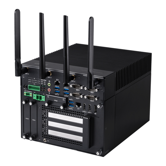
Serial Ports Power button Remote Power HDMI™ ports button connector DisplayPort Power input connector LAN port USB 3.2 Gen 2 ports Storage device bays Expansion card slots Functional Earth Ground Top: Nano SIM card slots Bottom: CFast slot PE400D Series... -
Page 11: I/O Ports And Leds
LED behaviour as well as their function. Item LED color Status Description On/Blink User defined User defined On/Blink User defined User defined On/Blink User defined Yellow User defined On/Blink User defined Yellow User defined PE400D Series... - Page 12 The high voltage protection can be used in industrial level uses. Please refer to the illustration below for the pin definition of the Isolated DIO connector. PE400D Series...
- Page 13 The USB 3.2 Gen 1 (Universal Serial Bus) port provides a transfer rate up to 10 Gbit/s. USB 3.2 Gen 1 port The USB 3.2 Gen 1 (Universal Serial Bus) port provides a transfer rate up to 5 Gbit/s. PE400D Series...
- Page 14 Please refer to the table below for the pin definitions of the different COM connectors. NOTE: Default set to RS-232. 1 2 3 4 5 RS-232 RS-422 RS485 DCD# 6 7 8 9 PE400D Series...
- Page 15 4096 x 2160 @ 30 Hz on external display devices. HDMI™ 2.0 port The integrated 19-pin HDMI (High Definition Multimedia Interface) port with a receptacle connector can support resolutions up to 4096 x 2160 @ 60 Hz on external display devices. PE400D Series...
- Page 16 This power input jack allows you to connect the bundled power terminal block to power jack adapter. Power supplied through this jack supplies power to the Edge Computer. Functional Earth Ground The Functional Earth Ground provides you with a grounding point. PE400D Series...
-
Page 17: Motherboard Overview
Motherboard Overview 1.2.1 Motherboard layout The PE400D is an Edge Computer based on a Pico-ITX motherboard. Please refer to the table for the page numbers of the numbered items. PE400D Series... - Page 18 Chassis Intrude header AT / ATX power selection HW WDT Enable jumper ME Lock jumper Mini PCIe / mSATA switch jumper CAN/COM switch jumpers I2C header M.2 E-key slot Mini PCIe / mSATA slot External Power Button connector PE400D Series...
-
Page 19: M-Key Slot
M.2 M-key slot The M.2 M-key slot allows you to install an M.2 module (M-key, type 2242/2260/2280) or M.2 B+M key TPU module. PE400D Series... -
Page 20: Spi Tpm Header
SPI TPM header The SPI TPM header supports a Trusted Platform Module (TPM) system, which can securely store keys, digital certificates, passwords, and data. A TPM system also helps enhance network security, protects digital identities, and ensures platform integrity. PE400D Series... -
Page 21: Chassis Intrude Header
NOTE: The default setting for this jumper is set to Chassis intruder - Close with a jumper cap attached. PE400D Series... -
Page 22: At / Atx Power Selection
If the jumper is attached, ATX power mode is set, if the jumper is removed, AT power mode will be set. NOTE: The default setting for this jumper is set to ATX mode with a jumper cap attached. PE400D Series... -
Page 23: Hw Wdt Enable Jumper
The HW WDT (watchdog timer) Enable jumper allows the HW watchdog resets the system automatically even when the system crashes. NOTE: The default setting for this jumper is set to HW WDT enabled with a jumper cap attached. PE400D Series... -
Page 24: Me Lock Jumper
IMPORTANT! Setting this jumper to ME Unlock and changing the Intel® ME without proper instructions may cause the BIOS to crash. NOTE: The default setting for this jumper is set to Me Lock with a jumper cap attached. PE400D Series... -
Page 25: Mini Pcie / Msata Switch Jumper
The Mini PCIe / mSATA switch jumper allows you to set the Mini PCIe /mSATA slot to either support a Mini PCIe card or mSATA card. NOTE: The default setting for this jumper is set to SATA mode with a jumper cap attached. PE400D Series... -
Page 26: Can/Com Switch Jumpers
The CAN / COM switch jumpers allows you to set COM4 to CAN bus or COM port. Both jumpers need to be set to the setting for the configuration to take effect. NOTE: The default setting for these jumpers are set to COM port with jumper caps attached. PE400D Series... -
Page 27: I2C Header
I2C header The I2C (Inter-Integrated Circuit) header allows you to connect an I2C compatible IoT security module. PE400D Series... -
Page 28: E-Key Slot
10. M.2 E-key slot The M.2 E-key slot allows you to install an M.2 Wi-Fi module (E-key, type 2230), or M.2 A+E key TPU module. PE400D Series... -
Page 29: Mini Pcie / Msata Slot
The Mini PCIe / mSATA slot allows you to install an LTE mPCIe module, mPCIe Coral TPU module or mSATA storage module. This slot can only support either Mini PCIe or mSATA, this can be adjusted with the Mini PCIe / mSATA switch jumper. PE400D Series... -
Page 30: External Power Button Connector
12. Remote Power Button connector The External Power Button connector allows you to attach the External power button terminal block to connect to an external power button. PE400D Series... -
Page 31: Chapter 2: Using Your Edge Computer
Using your Edge Computer... -
Page 32: Getting Started
Connect the power terminal block to power jack adapter to your Edge Computer’s power (DC) input, then secure it with the two screws on the power terminal block to power jack adapter cable. Plug the AC power adapter into a 100V~240V power source. PE400D Series... - Page 33 - Input voltage: 100-240 Vac - Input frequency: 50-60 Hz - Rating output current: 13.75A (65.0 W) - Rating output voltage: 24.0V • If you are using another power supply, ensure to use a 9Vdc-36Vdc, 36.66A-9.16A power supply. PE400D Series...
-
Page 34: Connect A Display Panel To Your Edge Computer
To connect a display panel to your Edge Computer: Connect one end of an HDMI™ cable to an external display, and the other end of the cable to your Edge Computer’s HDMI™ port. Connect display via HDMI™ port PE400D Series... - Page 35 Connect display via DisplayPort PE400D Series...
-
Page 36: Connect The Usb Cable From Keyboard Or Mouse
To connect a keyboard and mouse to your Edge Computer: Connect the USB cable from your keyboard and mouse to any of the USB ports of your Edge Computer. NOTE: • The keyboard varies with country or region. • The keyboard and mouse are purchased separately. PE400D Series... -
Page 37: Installing The Desk Mount
Edge Computer so that the Edge Computer sits upright with the top of the Edge Computer facing upwards to allow for efficient heat dissipation. Desk Mount Screw Length: 6.0 mm Diameter: 7.7 mm PE400D Series... -
Page 38: Turning Your Edge Computer Off
If your Edge Computer is unresponsive, press and hold the power button for at least four (4) seconds until your Edge Computer turns off. Putting your Edge Computer to sleep To put your Edge Computer on Sleep mode, press the Power button once. PE400D Series... -
Page 39: Chapter 3: Upgrading Your Edge Computer
Upgrading your Edge Computer... - Page 40 Turn off the power of your Edge Computer, and allow it to cool for at least 10 minutes before performing any installation/ uninstallation process. NOTE: The illustrations in this section are for reference only. The slots may vary depending on model. PE400D Series...
-
Page 41: Removing The Side Cover
Edge Computer on a flat stable surface, with its top side facing down. Remove the screw from the bottom of the Edge Computer. Loosen the two (2) thumbscrews on the rear of the Edge Computer securing the side cover. PE400D Series... - Page 42 Push the side cover towards the rear of the Edge Computer (A), then remove the side cover (B). PE400D Series...
-
Page 43: Replacing The Side Cover
Replacing the side cover Align the side cover with the latch holes on the chassis (A), then replace the side cover (B) and push it towards the front of the Edge Computer (C). PE400D Series... - Page 44 Secure the side cover with the two (2) thumbscrews on the rear of the Edge Computer (A), and the screw removed previously on the bottom of the Edge Computer (B). PE400D Series...
-
Page 45: Installing Memory Modules
(2) DDR4 SO-DIMMs, ECC*, with a maximum of 64GB. NOTE: ECC only available when using Xeon CPU. Align and insert the memory module into the slot (A) and press it down (B) until it is securely seated in place. PE400D Series... -
Page 46: Installing An Mpcie / Msata Module
LTE mPCIe module, mPCIe Coral TPU module or mSATA storage module. To install an LTE mPCIe module: Align and insert the LTE mPCIe module into the slot, press it down and secure it in place using two (2) screws. Connect the antennas to your LTE mPCIe module. PE400D Series... - Page 47 To install an mPCIe TPU module: Align and insert the mPCIe TPU module into the slot, press it down and secure it in place using two (2) screws. PE400D Series...
- Page 48 To install an mSATA storage module Align and insert the mSATA storage module into the slot, press it down and secure it in place using two (2) screws. PE400D Series...
-
Page 49: Installing An M.2 E Key Module
M.2 Wi-Fi module or M.2 A+E key Coral TPU module. To install an M.2 Wi-Fi module: Align and insert the M.2 Wi-Fi module into the slot, press it down and secure it in place using a screw. Connect the antenna to your M.2 Wi-Fi module. PE400D Series... - Page 50 To install an M.2 A+E key TPU module: Align and insert the M.2 A+E key TPU module into the slot, press it down and secure it in place using a screw. PE400D Series...
-
Page 51: Installing An M.2 M Key Module
Install the stand screw to a slot which matches the length of your M.2 SSD module. Align and insert the M.2 SSD into its slot inside the Edge Computer, then gently push down the M.2 SSD on top of the stand screw hole and fasten it using a screw. PE400D Series... - Page 52 To install an M.2 B+M key TPU module: Align and insert the M.2 B+M key TPU module into the slot, and secure it in place using a screw. PE400D Series...
-
Page 53: Installing A Pcie Expansion Card
NOTE: Supports max. length < 192mm, and max. 100W supply from mainboard for three (3) slots in total. To install a PCIe expansion card: Remove the screw securing the metal bracket of the PCIe expansion slot from the front of the Edge Computer, then remove the metal bracket. PE400D Series... - Page 54 Insert your PCIe expansion card to an empty PCIe slot and ensure the bracket of the PCIe expansion card is properly aligned to the opening on the front of the Edge Computer. PE400D Series...
- Page 55 Secure the PCIe expansion card using the screw removed previously. PE400D Series...
-
Page 56: Installing A Storage Device
Your may install up to two (2) 2.5” storage devices (hot-swappable, 7~7.5mm) to your Edge Computer. Loosen the two (2) thumbscrews of the storage device tray located on the front of your Edge Computer. Pull the storage device tray out of the chassis. PE400D Series... - Page 57 Install your storage device to the storage device tray, then secure it with four (4) screws. PE400D Series...
- Page 58 Edge Computer, the thumbscrews on the storage device tray should be properly aligned to the screw holes on the front of the Edge Computer when replacing the storage device tray. Push the thumbscrews down then tighten them to secure the storage device tray. PE400D Series...
-
Page 59: Replacing The Cmos Battery
Loosen the two (2) thumbscrews on the metal cover of the nano SIM card / CFast card combo slot. Carefully remove the metal cover. CAUTION! The battery is attached to the metal cover, please take caution when removing it so as not to damage the battery. PE400D Series... - Page 60 Carefully pull the battery cable outwards until the extension cable connector can be seen, then disconnect the battery cable from the extension cable. Remove the battery from the battery compartment on the metal cover. PE400D Series...
- Page 61 NOTE: You may remove the side cover to make it easier for you to push the extension cable into the Edge Computer chassis. For more information on removing the side cover, please refer to Removing the side cover. PE400D Series...
- Page 62 CAUTION! The battery is attached to the metal cover, please take caution when replacing it so as not to damage the battery. Push down on the two (2) thumbscrews, then tighten them to secure the metal cover. PE400D Series...
-
Page 63: Optional) Installing A Nano Sim Card
SIM card is pushed all the way into the nano SIM card slot. Follow steps 7 and 8 of Replacing the CMOS battery to replace the metal cover of the nano SIM card / CFast card combo slot. PE400D Series... -
Page 64: Installing A Cfast Card
Insert your CFast card into the CFast card slot. Ensure that the CFast card is pushed all the way into the CFast card slot. Follow steps 7 and 8 of Replacing the CMOS battery to replace the metal cover of the nano SIM card / CFast card combo slot. PE400D Series... -
Page 65: Appendix
Appendix... -
Page 66: Safety Information
- access is through the use of a TOOL or lock and key, or other means of security, and is controlled by the authority responsible for the location. • This device shall not be connected to an Ethernet network with outside plant routing. PE400D Series... -
Page 67: Care During Use
This symbol of the crossed out wheeled bin indicates that the product (electrical, electronic equipment, and mercury-containing button cell battery) should not be placed in municipal waste. Check local technical support services for product recycling. PE400D Series... -
Page 68: Regulatory Notices
IMPORTANT! Outdoor operations in the 5.15~5.25 GHz band is prohibited. This device has no Ad-hoc capability for 5250~5350 and 5470~5725 MHz. CAUTION! Any changes or modifications not expressly approved by the grantee of this device could void the user’s authority to operate the equipment. PE400D Series... - Page 69 RF exposure compliance. Operation is subject to the following two conditions: • This device may not cause interference and • This device must accept any interference, including interference that may cause undesired operation of the device. PE400D Series...
- Page 70 Ch01 through CH11 Japan 2.412-2.484 GHz Ch01 through Ch14 Europe ETSI 2.412-2.472 GHz Ch01 through Ch13 KC: Korea Warning Statement Class A: 사용자 안내문 이 기기는 업무용 환경에서 사용할 목적으로 적합성평가를 받은 기기로서 가정용 환경에서 사용하는 경우 전파간섭의 우려가 있습니다. PE400D Series...
- Page 71 用が禁じられています。 法律および規制遵守 本製品は電波法及びこれに基づく命令の定めるところに従い使用してくだ さい。 日本国外では、 その国の法律ま たは規制により、 本製品の使用ができないことがあります。 このような国で は、 本製品を運用した結果、 罰せられ ることがありますが、 当社は一切責任を負いかねますのでご了承ください。 HDMI Compliance Statement The terms HDMI, HDMI High-Definition Multimedia Interface, and the HDMI Logo are trademarks or registered trademarks of HDMI Licensing Administrator, Inc. PE400D Series...
- Page 72 ASUS products sold in Vietnam, on or after September 23, 2011,meet the requirements of the Vietnam Circular 30/2011/TT-BCT. Các sản phẩm ASUS bán tại Việt Nam, vào ngày 23 tháng 9 năm2011 trở về sau, đều phải đáp ứng các yêu cầu của Thông tư 30/2011/TT-BCT của Việt Nam.
- Page 73 All ASUS products with the ENERGY STAR logo comply with the ENERGY STAR standard, and the power management feature is enabled by default. The monitor is automatically set to sleep within 10 minutes of user inactivity;...
-
Page 74: Service And Support
Service and Support Visit our multi-language website at https://www.asus.com/support/. Manufacturer ASUSTeK Computer Inc. Tel: +886-2-2894-3447 Address: 1F., No. 15, Lide Rd., Beitou Dist., Taipei City 112, Taiwan Authorised ASUSTeK Computer GmbH representative in Address: Harkortstrasse 21-23, 40880 Ratingen, Germany Europe...
Need help?
Do you have a question about the PE400D Series and is the answer not in the manual?
Questions and answers