Table of Contents
Advertisement
Quick Links
Advertisement
Chapters
Table of Contents

Subscribe to Our Youtube Channel
Related Manuals for Asus PE200S Series


Summary of Contents for Asus PE200S Series
- Page 1 PE200S Series Desktop PC User Manual...
- Page 2 Copyright © 2019 ASUSTeK COMPUTER INC. All Rights Reserved. LIMITATION OF LIABILITY Circumstances may arise where because of a default on ASUS’ part or other liability, you are entitled to recover damages from ASUS. In each such instance, regardless of the basis on which you are entitled to claim damages from ASUS, ASUS is liable for no more than damages for bodily injury (including death) and damage to real property and tangible personal property;...
-
Page 3: Table Of Contents
2.1.2 Connect a display panel to your Edge Computer ..........38 2.1.3 Connect the USB cable from keyboard or mouse ..........40 2.1.4 Turn on your Edge Computer .................. 41 2.2 Turning your Edge Computer off...............42 2.3 Putting your Edge Computer to sleep .............42 PE200S Series... - Page 4 4.4.3 Onboard Devices Configuration ................73 4.4.4 ACPI Settings ......................... 75 4.4.5 APM Configuration ...................... 76 4.4.6 SMART Settings ......................77 4.4.7 NCT6116D Super IO Configuration ................ 77 4.4.8 NCT6116D HW Monitor ..................... 79 4.4.9 Serial Port Console Redirection................79 PE200S Series...
- Page 5 4.5 Security ........................94 4.6 Boot menu .........................97 4.7 Save & Exit menu .....................101 4.8 Updating your BIOS ....................102 4.8.1 ASUS CrashFree BIOS 3 utility .................. 102 4.8.2 ASUS EzFlash Utility ..................... 103 4.8.3 BUPDATER utility ......................105 Appendix Safety information ......................108 Setting up your system ......................
-
Page 6: About This Manual
Edge Computer. Chapter 4: BIOS Setup This chapter tells how to change system settings through the BIOS Setup menus. Detailed descriptions of the BIOS parameters are also provided. Appendix This section includes notices and safety statements your Edge Computer. PE200S Series... -
Page 7: Conventions Used In This Manual
Edge Computer's data and components. Typography Bold text Indicates a menu or an item to select. Italic This indicates sections that you can refer to in this manual. PE200S Series... -
Page 8: Package Contents
Package contents Your Edge Computer package contains the following items: PE200S Series AC power adapter* Power cord* Wall mount kit SATA and power cable PE200S Series... - Page 9 • T he device illustration is for reference only. Actual product specifications may vary with models. • I f the device or its components fail or malfunction during normal and proper use within the warranty period, bring the warranty card to the ASUS Service Center for replacement of the defective components. PE200S Series...
- Page 10 PE200S Series...
-
Page 11: Chapter 1: Getting To Know Your Edge Computer
Getting to know your Edge Computer... -
Page 12: Features
The Intel I210-AT Gigabit Ethernet controllers with 8-pin RJ-45 LAN port supports a standard Ethernet cable for connection to a local network. USB 3.2 Gen 1 port The USB 3.2 Gen 1 (Universal Serial Bus) port provides a transfer rate up to 5 Gbit/s. PE200S Series... - Page 13 The 9-pin RS232/422/485 serial (COM) connector allows you to connect devices that have serial ports such as bar code scanner, modem, or printers. Please refer to the table below for the pin definitions of the different COM connectors. 1 2 3 4 5 RS-232 RS-422 RS485 DCD# 6 7 8 9 PE200S Series...
- Page 14 Please refer to the table below for the pin definition of the GPIO connector. 5 4 3 2 1 GPIO DIO_0 DIO_4 9 8 7 6 DIO_1 DIO_5 DIO_2 DIO_6 DIO_3 DIO_7 PE200S Series...
-
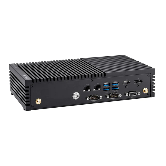
Page 15: Rear View
6 7 8 9 USB 2.0 port (on selected models) The USB (Universal Serial Bus) port is compatible with USB 2.0 or USB 1.1 devices such as keyboards, pointing devices, flash disk drives, external HDDs, speakers, cameras and printers. PE200S Series... - Page 16 Do not cover the adapter and keep it away from your body. Antenna hole The antenna hole allows you to connect a wireless antenna to enhance wireless signal reception. Headphone jack This port allows you to connect amplified speakers or headphones. PE200S Series...
-
Page 17: Motherboard Overview
Motherboard Overview 1.2.1 Motherboard layout The PE200S Series features a motherboard with a 3.5” dimension (146mm x 105mm). Please refer to the table on the next page for the page numbers of the numbered items. PE200S Series... - Page 18 Micro SD card slot M.2 slot USB 2.0 connector DC-in 4-Pin Power connector SATA 6Gb/s & SATA Power connector DC-in 4-Pin Power connector HW WDT Enable jumper SPI TPM connector System Panel connector Line Out / Mic connector PE200S Series...
-
Page 19: System Memory
1.2.2 System memory The motherboard comes with a Small Outline Dual Inline Memory Module (SODIMM) slot designed for DDR3L memory modules. PE200S Series... -
Page 20: Onboard Jumpers
NOTE: If the steps above do not help, remove the onboard button cell battery and move the jumper again to clear the CMOS RTC RAM data. After clearing the CMOS, reinstall the button cell battery. PE200S Series... -
Page 21: Hw Wdt Enable Jumper
The HW WDT (watchdog timer) Enable jumper allows the HW watchdog resets the system automatically even when the system crashes. NOTE: The default setting for this jumper is set to HW WDT enabled with a jumper cap attached. PE200S Series... -
Page 22: Internal Connectors
SATA cable and power cable. Connector type Wafer HD 4P, 2.0mm pitch NOTE: Ensure to use the bundled cable when connecting a storage device to this connector. PE200S Series... -
Page 23: Mini Pcie Slot
The Mini PCIe slot allows you to install a Mini PCIe peripheral device. NOTE: The Mini PCIe peripheral device is purchased separately. Micro SD Card slot The Micro SD Card slot allows you to install a Micro SD card. NOTE: The Micro SD card is purchased separately. PE200S Series... -
Page 24: Wi-Fi Slot
The Nano SIM Card slot allows you to install a Nano SIM card. NOTE: The Nano SIM card is purchased separately. M.2 Wi-Fi slot The M.2 Wi-Fi slot allows you to install an M.2 Wi-Fi module (E-key, type 2230). NOTE: The M.2 Wi-Fi module is purchased separately. PE200S Series... -
Page 25: Power Button Connector
M.2 slot The M.2 slot allows you to install 2242 M.2 devices such as 2242 M.2 SSD modules. NOTE: • The M.2 SSD module is purchased separately. • This motherboard supports 2242 SATA SSD devices only. Power button connector The Power Button connector allows you to connect an external power button. PE200S Series... -
Page 26: Low Pin Count Connector
The Low Pin Count connector allows you to connect a low pin count (LPC) debug card that offers a faster, more efficient motherboard troubleshooting solution. When connected to a debug card, users can view error and debugging codes on the card and get a better idea of initialization and recovery processes. Connector type BOX header 2x5p, K10, 2.0mm pitch PE200S Series... -
Page 27: Gpio Connector
Header 1x4p, 2.0mm pitch 11. GPIO connector The GPIO connector allows you to connect a general purpose input/ output module which allows you to customize the digital signal input/ output. Connector type BOX header 2x5p, K9, 2.0mm pitch PE200S Series... -
Page 28: I2C Connector
The SPI TPM connector supports a Trusted Platform Module (TPM) system, which can securely store keys, digital certificates, passwords, and data. A TPM system also helps enhance network security, protects digital identities, and ensures platform integrity. Connector type Header 2x7p,K14, 2.0mm pitch PE200S Series... -
Page 29: Serial Port Connector
Connect the serial port module cable to this connector, then install the module to a slot opening on the system chassis. Connector type BOX header 2x5p, K10, 2.0mm pitch NOTE: • The serial port module is purchased separately. COM1 and COM2 support RS-232/422/485. • COM 3, COM4, COM5, and COM6 support RS-232. • PE200S Series... -
Page 30: Usb 2.0 Connector
480 MB/s connection speed. Connector type BOX header 2x5p, K9, 2.0mm pitch WARNING! DO NOT connect a 1394 cable to the USB connectors. Doing so will damage the motherboard! NOTE: The USB 2.0 module is purchased separately. PE200S Series... -
Page 31: Chassis Intrusion Connector
NOTE: By default, a jumper cap that disables the intrusion detection feature is installed on the connector to prevent accidental triggers. PE200S Series... -
Page 32: System Panel Connector
The 3-1 pin connector allows you to connect the system power button. Press the power button to power up the system, or put the system into sleep or soft-off mode (depending on the operating system settings). • Reset button connector (RESET) The 2-pin connector allows you to connect the chassis-mounted reset button. Press the reset button to reboot the system. PE200S Series... -
Page 33: Line Out / Mic Connector
HD Audio. Connect one end of the line Out / mic module cable to this connector. Connector type BOX header 2x5p, K8, 2.0mm pitch NOTE: We recommend that you connect a high-definition line out / mic module to this connector to avail of the motherboard’s high- definition audio capability. PE200S Series... -
Page 34: Dc-In 4-Pin Power Connector
19. DC-in 4-Pin Power connector The DC-in 4-pin Power connector is for DC power input. Using a compatible power cable and power board, you may connect a suitable power supply with DC -in jacks. Connector type POWER CON 4P R/A PE200S Series... -
Page 35: Chapter 2: Using Your Edge Computer
Using your Edge Computer... -
Page 36: Getting Started
Connect the power cord to the AC power adapter. Connect the DC power connector into your Edge Computer’s power (DC) input. Plug the AC power adapter into a 100V~240V power source. NOTE: The power adapter may vary in appearance, depending on models and your region. PE200S Series... -
Page 37: Dc-In 4-Pin Power Connector
Edge Computer from the power socket. NOTE: The power adapter may vary between models and territories, please refer to the following for more information on the different adapters: 65W Power adapter • Input voltage: 100-240 Vac • Input frequency: 50-60 Hz • Rating output current: 3.42 A (65 W) • Rating output voltage: 19 V 120W Power adapter • Input voltage: 100-240 Vac • Input frequency: 50-60 Hz • Rating output current: 6.32A max. (120W) • Rating output voltage: 19 V PE200S Series... -
Page 38: Connect A Display Panel To Your Edge Computer
To connect a display panel to your Edge Computer: Connect one end of an HDMI, or a DisplayPort cable to an external display, and the other end of the cable to your Edge Computer’s HDMI port, or DisplayPort. Connect display via HDMI port PE200S Series... - Page 39 Connect display via DisplayPort PE200S Series...
-
Page 40: Connect The Usb Cable From Keyboard Or Mouse
Computer. You can also connect a USB dongle for a wireless keyboard and mouse set. To connect a keyboard and mouse to your Edge Computer: Connect the USB cable from your keyboard and mouse to any of the USB ports of your Edge Computer. NOTE: • The keyboard varies with country or region. • The keyboard and mouse are purchased separately. PE200S Series... -
Page 41: Turn On Your Edge Computer
2.1.4 Turn on your Edge Computer Press the power button to turn on your Edge Computer. PE200S Series... -
Page 42: Turning Your Edge Computer Off
Turning your Edge Computer off If your Edge Computer is unresponsive, press and hold the power button for at least four (4) seconds until your Edge Computer turns off. Putting your Edge Computer to sleep To put your Edge Computer on Sleep mode, press the Power button once. PE200S Series... -
Page 43: Chapter 3: Upgrading Your Edge Computer
Upgrading your Edge Computer... -
Page 44: Removing The Bottom Cover
Remove the four (4) rubber feet screws from the bottom cover. Remove the four (4) screws securing the bottom cover. After removing the screws, remove the bottom cover and place it aside. PE200S Series... -
Page 45: Replacing The Bottom Cover
Replacing the bottom cover Align the bottom cover with the screw holes, then replace the bottom cover onto the Edge Computer. Secure the bottom cover using the four (4) screws removed previously. Replace the four (4) rubber feet screws removed previously. PE200S Series... -
Page 46: Installing Memory Modules
Your Edge Computer comes with a SO-DIMM memory slot that allow you to install a DDR3L SO-DIMM. Align and insert the memory module into the slot (A) and press it down (B) until it is securely seated in place. PE200S Series... -
Page 47: Installing 2.5" Storage Device
Connect the storage device cable to the storage device. Insert your storage device into the storage bay. Secure the storage device to the storage bay using four (4) screws. IMPORTANT! This device only supports 7mm 2.5” HDD or SSD. PE200S Series... - Page 48 Connect the storage device cable to the SATA6G and SATA_PWR connectors on the motherboard. Replace the bottom cover, then secure the bottom cover using the four (4) screws removed previously. Replace the four (4) rubber feet screws removed previously. PE200S Series...
-
Page 49: Installing The Mini Pcie Card
Your Edge Computer comes with a Mini PCIe slot that allow you to install a Mini PCIe peripheral card. Align and insert the Mini PCIe card into the slot (A) and press it down and secure it in place using two (2) screws. PE200S Series... -
Page 50: Installing A Nano Sim Card
Push the nano SIM cover towards the front of your Edge Computer. Lift the nano SIM cover. Place the nano SIM into the nano SIM slot. Replace the nano SIM cover. Push the nano SIM cover towards the rear of your Edge Computer to secure the nano SIM card. PE200S Series... -
Page 51: Installing An Sd Card
Remove the five (5) screws on the rear cover, then slightly pull the rear cover outwards, but do not remove it completely. Insert your SD card into the SD card slot. Ensure that the SD card is pushed all the way into the SD card slot. PE200S Series... - Page 52 Once your SD card is properly installed into the SD card slot, replace the rear cover and secure it using the five (5) screws removed previously. PE200S Series...
-
Page 53: Installing The Wireless Card
(optional) Connect the antennas to your wireless card. NOTE: • P lease refer to the Installing the antennas section for more information on installing the antennas. • C onnecting antennas to your wireless card may strengthen the wireless signal. • A soft clicking sound indicates that the antenna has been securely attached on the wireless card. PE200S Series... -
Page 54: Installing An M.2 Ssd
(optional) Replace the stand screw if it has been removed. Align and insert the M.2 SSD into its slot inside the Edge Computer, then gently push down the M.2 SSD on top of the stand screw hole and fasten it using a screw. PE200S Series... -
Page 55: Installing The Antennas (Optional)
Insert the bundled O-ring to the antenna jack, then secure the antenna jack using bundled hex screw. Connect the other end of the RF connector and cable to your wireless card or WWAN card. Repeat steps 1 to 5 to install additional antennas. PE200S Series... -
Page 56: Installing The Usb 2.0 Module (On Selected Models)
Connect the USB 2.0 module connector to the USB 2.0 connector on the motherboard. NOTE: Please refer to the Motherboard layout section for the location of the USB 2.0 connectors. To install another USB 2.0 module, please repeat steps 1-3. PE200S Series... -
Page 57: Installing The Serial Port Module (On Selected Models)
Connect the Serial port module connector to the Serial port connector on the motherboard. NOTE: Please refer to the Motherboard layout section for the location of the Serial port connectors. To install another Serial port module, please repeat steps 1-3. PE200S Series... -
Page 58: Installing The Poe Lan Module (On Selected Models)
(2) bundled LAN signal cables. NOTE: Ensure to connect the CN1 connector on the daughter board to the CN1 connector on the motherboard, and the CN2 connector on the daughter board to the CN2 connector on the motherboard. daughter board motherboard PE200S Series... - Page 59 Connect the power connector on the daughter board to the power connector on the power board. Secure the motherboard and daughter board using the bundled screws. PE200S Series...
-
Page 60: Installing The Vesa Mount (Optional)
Place your Edge Computer upside down on a flat and stable surface. Attach the bundled two (2) 12mm screws into the screw holes at the bottom of your Edge Computer. Remove the screw hole covers at the back of your VESA mount- compatible device, if any. PE200S Series... - Page 61 Position the Edge Computer and insert the screws attached on the Edge Computer to the mounting holes of the VESA mounting plate (A), then gently push the Edge Computer down in the angle shown in the illustration to secure it in place (B). PE200S Series...
-
Page 62: Installing The Wall Mount
Remove the four (4) rubber feet screws. Align the wall mount with the rubber feet screw holes (A), then remove the rubber feet from the rubber feet screws (B) and secure the wall mount to your Edge Computer using the rubber feet screws (C). PE200S Series... -
Page 63: Chapter 4: Bios Setup
BIOS Setup... -
Page 64: Getting To Know Your Bios
• An error message appears on the screen during the system bootup and requests you to run the BIOS setup. • You have installed a new system component that requires further BIOS settings or update. WARNING! Inappropriate BIOS settings may result to instability or boot failure. We strongly recommend that you change the BIOS settings only with the help of a trained service personnel. PE200S Series... -
Page 65: Bios Setup Program
Press <Delete> or <F2> during the Power-On Self Test (POST). If you do not press <Delete> or <F2>, POST continues with its routines. Entering BIOS Setup after POST To enter BIOS Setup after POST: • Press <Ctrl>+<Alt>+<Delete> simultaneously. • Press the power button to turn the system off then back on. Do this option only if you failed to enter BIOS Setup using the first option. PE200S Series... - Page 66 For changing the basic system configuration Advanced For changing the advanced system settings Security For changing the security settings Boot For changing the system boot configuration Exit For selecting the save and exit options or loading default settings PE200S Series...
-
Page 67: Main Menu
Scroll down to display the other BIOS items. 4.3.1 System Date [Day xx/xx/xxxx] Allows you to set the system date. 4.3.2 System Time [xx:xx:xx] Allows you to set the system time. PE200S Series... -
Page 68: Advanced Menu
Incorrect field values can cause the system to malfunction. Start ASUS EzFlash Allows you to run ASUS EzFlash BIOS ROM Utility when you press <Enter>. Refer to the ASUS EzFlash Utility section for details. WARNING! Ensure to back up your Bitlocker recovery key and suspend Bitlocker encryption in the operating system before updating your BIOS. -
Page 69: Trusted Computing
4.4.1 Trusted Computing NOTE: All values changed here do not take effect until computer is restarted. Security Device Support Allows you to enable or disable the BIOS support for security device. Configuration options: [Disable] [Enable] NOTE: The following items appear only when Security Device Support is set to [Enabled]. PE200S Series... - Page 70 Configuration options: [Disabled] [Enabled] TPM2.0 UEFI Spec Version Allows you to select the TCG2 spec version support. [TCG_1_2] Compatible mode for Windows 8 / Windows ® ® [TCG_2] Supports new TCG2 protocol and event format for Windows ® or later. PE200S Series...
-
Page 71: Pch Storage Configuration
Allows you to enable or disable the Chipset SATA Controller. Configuration options: [Disabled] [Enabled] SMART Self Test SMART (Self-Monitoring, Analysis and Reporting Technology) is a monitoring system that shows a warning message during POST (Power-On Self Test) when an error occurs in the hard disks. Configuration options: [Disabled] [Enabled] PE200S Series... - Page 72 Configuration options: [Disabled] [Enabled] M.2(SOCKET3) M.2(SOCKET3) Port Allows you to enable or disable the M.2(SOCKET3) port. Configuration options: [Disabled] [Enabled] M.2(SOCKET3) Port Hot Plug Allows you to enable or disable M.2(SOCKET3) Hot Plug Support. Configuration options: [Disabled] [Enabled] PE200S Series...
-
Page 73: Onboard Devices Configuration
Intel LAN 2 Allows you to enable or disable Intel LAN 2. Configuration options: [Disabled] [Enabled] Intel LAN 2 PXE Option ROM Allows you to enable or disable Intel LAN 2 PXE OPROM launch. Configuration options: [Disabled] [Enabled] PE200S Series... - Page 74 Configuration options: [Disabled] [Enabled] I2C Controller Allows you to enable or disable I2C Controller Support. Configuration options: [Disabled] [Enabled] IO Expander Configuration IO Expander GPIO 0-7 Direction Allows you to select the direction of the GPIO. Configuration options: [Output] [Input] PE200S Series...
-
Page 75: Acpi Settings
Allows you to select the highest ACPI sleep state the system will enter when the SUSPEND button is pressed. Configuration options: [Suspend Disabled] [S3 (Suspend to RAM)] Lock Legacy Resources Allows you to enable or disable the Lock of Legacy Resources. Configuration options: [Disabled] [Enabled] PE200S Series... -
Page 76: Apm Configuration
Enables the Ring devices to generate a wake event. Power On By RTC [Disabled] Disables RTC to generate a wake event. When set to [Enabled], the items RTC Alarm Date (Days) and [Enabled] Hour/Minute/Second will become user-configurable with set values. PE200S Series... -
Page 77: Smart Settings
Allows you to run SMART Self Test on all HDDs during POST. Configuration options: [Disabled] [Enabled] 4.4.7 NCT6116D Super IO Configuration Serial Port 1-2 Configuration Allows you to set the parameters of Serial Port 1-2. Serial Port Allows you to enable or disable Serial Port. Configuration options: [Disabled] [Enabled] PE200S Series... - Page 78 Configuration options: [Auto] [IO=3F8h; IRQ=4;] [IO=3F8h; IRQ=3, 4, 5, 6, 7, 9, 10, 11, 12;] [IO=2F8h; IRQ=3, 4, 5, 6, 7, 9, 10, 11, 12;] [IO=3E8h; IRQ=3, 4, 5, 6, 7, 9, 10, 11, 12;] [IO=2E8h; IRQ=3, 4, 5, 6, 7, 9, 10, 11, 12;] PE200S Series...
-
Page 79: Nct6116D Hw Monitor
4.4.8 NCT6116D HW Monitor 4.4.9 Serial Port Console Redirection COM1-6 Console Redirection Allows you to enable or disable the console redirection feature. Configuration options: [Disabled] [Enabled] PE200S Series... - Page 80 0 if the num of 1’s in the data bits is even. [Odd] parity bit is 0 if num of 1’s in the data bits is odd. [Mark] parity bit is always 1. [Space] parity bit is always 0. PE200S Series...
- Page 81 Configuration options: [VT100] [Intel Linux] [XTERMR6] [SCO] [ESCN] [VT400] Legacy Console Redirection Settings Redirection COM Port Allows you to select a COM port to display redirection of Legacy OS and Legacy OPROM Messages. Configuration options: [COM1] [COM2] [COM3] [COM4] [COM5] [COM6] PE200S Series...
- Page 82 Configuration options: [COM1] [COM2] [COM3] [COM4] [COM5] [COM6] Terminal Type Allows you to set the terminal type for out-of-band management. Configuration options: [VT100] [VT100+] [VT-UTF8] [ANSI] Bits per second Allows you to set the serial port transmission speed. Configuration options: [9600] [19200] [57600] [115200] PE200S Series...
-
Page 83: Cpu Configuration
EIST Allows you to enable or disable Intel SpeedStep. Configuration: [Disabled] [Enabled] NOTE: The following item appears only when EIST is set to [Enabled]. Turbo Mode Allows you to enable or disable Turbo Mode. Configuration options: [Disabled] [Enabled] PE200S Series... - Page 84 Allows you to configure the demotion of the C-State. Configuration options: [Disabled] [C1] C-State Un-demotion Allows you to configure the un-demotion of the C-State. Configuration options: [Disabled] [C1] Power Limit 1 Enable Allows you to enable or disable Power Limit 1. Configuration options: [Disabled] [Enabled] PE200S Series...
- Page 85 Allows you to enable or disable selecting the number of CPU cores to activate in each processor package. Configuration options: [Disabled] [Enabled] NOTE: The following items appear only when Active Processor Cores is set to [Enabled]. Core 1-3 Allows you to enable or Core 1-3. Configuration options: [Disabled] [Enabled] PE200S Series...
- Page 86 Allows you to enable or disable Monitor Mwait. Configuration options: [Disabled] [Enabled] P-STATE Coordination Allows you to change the P-STATE Coordination type. Configuration options: [HW_ALL] [SW_ALL] [SW_ANY] Allows you to enable or disable the Digital Thermal Sensor. Configuration options: [Disabled] [Enabled] PE200S Series...
-
Page 87: Ami Graphic Output Protocol Policy
4G address space. It only works if the system supports 64-bit PCI decoding. Configuration options: [Disabled] [Enabled] BME DMA Mitigation Allows you to re-enable Bus Master Attribute disabled during Pci enumeration for PCI Bridges after SMM Locked. Configuration options: [Disabled] [Enabled] PE200S Series... -
Page 88: Usb Configuration
Enables the support for USB devices on legacy operating systems (OS). [Auto] Allows the system to detect the presence of USB devices at startup. If detected, the USB controller legacy mode is enabled. If no USB device is detected, the legacy USB support is disabled. PE200S Series... - Page 89 OS. Configuration options: [Disabled] [Enabled] U2_P5-6 Allows you to enable or disable USB port. Once set to [Disabled], any USB devices plugged into the connector will not be detected by BIOS or OS. Configuration options: [Disabled] [Enabled] PE200S Series...
-
Page 90: Network Stack Configuration
Enables or disables the Ipv4 PXE Boot Support. If disabled, Ipv4 PXE boot option will not be created. Configuration options: [Disabled] [Enabled] Ipv6 PXE Support Enables or disables the Ipv6 PXE Boot Support. If disabled, Ipv6 PXE boot option will not be created. Configuration options: [Disabled] [Enabled] PE200S Series... -
Page 91: Sdio Configuration
Allows you to select the TPM device. [Firmware TPM] Enables PTT in SkuMgr. [Discrete TPM] Disables PTT in SkuMgr. WARNING! Selecting [Discrete TPM] will disable PTT and Discrete TPM, and all data saved on it will be lost. PE200S Series... -
Page 92: Security Configuration
Allows you to configure _CRT, _PSV, and _ACO automatically based on values recommended in BWG’s Thermal Reporting for Thermal Management settings. Set to [Disabled] for manual configuration. Configuration options: [Disabled] [Enabled] NOTE: The following items appear only when Automatic Thermal Reporting is set to [Disabled]. PE200S Series... - Page 93 Configuration options: [15 C] [23 C] [31 C] [39 C] [47 C] [55 C] [60 C] [63 C] [71 C] [79 C] [87 C] [95 C] [103 C] [110 C] NOTE: Please ignore this item for a Fanless system. PE200S Series...
-
Page 94: Security
Select the Administrator Password item and press <Enter>. From the Enter Current Password box, key in the current password, then press <Enter>. From the Create New Password box, key in a new password, then press <Enter>. Confirm the password when prompted. PE200S Series... - Page 95 From the Create New Password box, key in a new password, then press <Enter>. Confirm the password when prompted. To clear a user password: Select the Clear User Password item and press <Enter>. Select Yes from the Warning message window then press <Enter>. PE200S Series...
- Page 96 Copy NVRAM content of source Boot variables to files in a root folder on a file system device. Platform Key (PK) Configuration options: [Details] [Export] [Update] [Delete] Key Exchange Keys / Authorized Signatures / Forbidden Signatures Configuration options: [Details] [Export] [Update] [Append] [Delete] PE200S Series...
-
Page 97: Boot Menu
NOTE: The following items appear only when Fast Boot is set to [Enabled]. SATA Support [Last Boot SATA Devices Only] Only last boot SATA device will be available in POST. [All SATA Devices] All SATA devices will be available in OS and POST. PE200S Series... - Page 98 Configuration options: [Disabled] [Enabled] NOTE: The following items appear only when CSM Support is set to [Enabled]. Boot Option filter This option allows you to control the Legacy/UEFI ROMs priority. Configuration options: [UEFI and Legacy] [Legacy only] [UEFI only] PE200S Series...
- Page 99 Allows you to select a desired additional POST waiting time to easily enter the BIOS Setup. You can only execute the POST delay time during normal boot. The values range from 0 to 10 seconds. NOTE: This feature only works when set under normal boot. PE200S Series...
- Page 100 T o access Windows® OS in Safe Mode, press <F8> after POST (Windows® 8 not supported). • T o select the boot device during system startup, press <F8> when the ASUS Logo appears. Boot Override These items displays the available devices. The number of device items that appears on the screen depends on the number of devices installed in the system.
-
Page 101: Save & Exit Menu
<F10> from the legend bar to exit. Discard Changes and Exit Exit System setup without saving any changes. Save Changes and Reset Exit System setup after saving the changes. Restore Defaults Restore/load default values for all the setup options. PE200S Series... -
Page 102: Updating Your Bios
4.8.1 ASUS CrashFree BIOS 3 utility The ASUS CrashFree BIOS 3 is an auto recovery tool that allows you to restore the BIOS file when it fails or gets corrupted during the updating process. You can update a corrupted BIOS file using a USB flash drive that contains the updated BIOS file. -
Page 103: Asus Ezflash Utility
BIOS file. 4.8.2 ASUS EzFlash Utility The ASUS EzFlash Utility feature allows you to update the BIOS using a USB flash disk without having to use a DOS-based utility. IMPORTANT! Download the latest BIOS from the ASUS website at www.asus.com before using this utility. - Page 104 Enter the BIOS setup program. Go to the Advanced menu to select Start ASUS EzFlash and press <Enter> to enable it. WARNING! Ensure to back up your Bitlocker recovery key and suspend Bitlocker encryption in the operating system before updating your BIOS.
-
Page 105: Bupdater Utility
USB flash disk drive with the updated BIOS file. Updating the BIOS file To update the BIOS file using the BUPDATER utility: Visit the ASUS website at www.asus.com and download the latest BIOS file for the motherboard. Save the BIOS file to a bootable USB flash disk drive. - Page 106 BIOS to prevent system boot failure! The utility returns to the DOS prompt after the BIOS update process is completed. Reboot the system from the hard disk drive. The BIOS update is finished! Please restart your system. C:\> PE200S Series...
-
Page 107: Appendix
Appendix... -
Page 108: Safety Information
- access is through the use of a TOOL or lock and key, or other means of security, and is controlled by the authority responsible for the location. • This device shall not be connected to an Ethernet network with outside plant routing. PE200S Series... -
Page 109: Care During Use
This symbol of the crossed out wheeled bin indicates that the product (electrical, electronic equipment, and mercury-containing button cell battery) should not be placed in municipal waste. Check local technical support services for product recycling. PE200S Series... -
Page 110: Regulatory Notices
ASUS REACH website at http://csr.asus.com/ english/REACH.htm ASUS Recycling/Takeback Services ASUS recycling and takeback programs come from our commitment to the highest standards for protecting our environment. We believe in providing solutions for you to be able to responsibly recycle our products, batteries, other components, as well as the packaging materials. - Page 111 IMPORTANT! Outdoor operations in the 5.15~5.25 GHz band is prohibited. This device has no Ad-hoc capability for 5250~5350 and 5470~5725 MHz. CAUTION! Any changes or modifications not expressly approved by the grantee of this device could void the user’s authority to operate the equipment. PE200S Series...
- Page 112 Le présent appareil est conforme aux CNR d’Innovation, Sciences et Développement économique Canada applicables aux appareils radio exempts de licence. L’exploitation est autorisée aux deux conditions suivantes : (1) l’appareil ne doit pas produire de brouillage, et (2) l’utilisateur de l’appareil doit accepter tout brouillage radioélectrique subi, même si le brouillage est susceptible d’en compromettre le fonctionnement. CAN ICES-3(A)/NMB-3(A) PE200S Series...
- Page 113 Europe ETSI 2.412-2.472 GHz Ch01 through Ch13 Regional notice for Singapore Complies with This ASUS product complies with IMDA Standards. IMDA Standards DB103778 Regional notice for California WARNING! This product contains chemicals known to the State of California to cause cancer, and birth defects or other reproductive harm.
- Page 114 Agency and the U.S. Department of Energy helping us all save money and protect the environment through energy efficient products and practices. All ASUS products with the ENERGY STAR logo comply with the ENERGY STAR standard, and the power management feature is enabled by default.
-
Page 115: Asus Contact Information
+1-510-608-4555 Web site http://www.asus.com/us/ Technical Support Support fax +1-812-284-0883 Telephone +1-812-282-2787 Online support https://www.asus.com/support/Product/ContactUs/Services/ questionform/?lang=en-us ASUS COMPUTER GmbH (Germany and Austria) Address Harkort Str. 21-23, 40880 Ratingen, Germany +49-2102-959931 Web site http://www.asus.com/de Online contact http://eu-rma.asus.com/sales Technical Support Telephone +49-2102-5789555 Support Fax... - Page 116 PE200S Series...
Need help?
Do you have a question about the PE200S Series and is the answer not in the manual?
Questions and answers