Table of Contents
Advertisement
Advertisement
Table of Contents

Related Manuals for Asus P4-P5G41


Summary of Contents for Asus P4-P5G41
- Page 1 P2-P5G41/P4-P5G41 ASUS PC (Desktop Barebone) User Manual...
- Page 2 Product warranty or service will not be extended if: (1) the product is repaired, modified or altered, unless such repair, modification of alteration is authorized in writing by ASUS; or (2) the serial number of the product is defaced or missing.
-
Page 3: Table Of Contents
2.3.2 Drivers menu ..............2-4 2.3.3 Utilities menu ..............2-5 2.3.4 Manual menu ..............2-6 2.3.5 ASUS Contact information ..........2-6 2.3.6 Other information ............2-7 ASUS AI Manager ................. 2-9 2.4.1 Installing AI Manager ............2-9 2.4.2 Launching AI Manager ............ 2-9 2.4.3... - Page 4 4.1.1 Creating a bootable floppy disk ........4-2 4.1.2 AFUDOS utility ..............4-3 4.1.3 ASUS CrashFree BIOS 3 utility ........4-6 4.1.4 ASUS EZ Flash 2 utility ........... 4-8 4.1.5 ASUS Update utility ............4-9 BIOS setup program ..............4-12 4.2.1...
- Page 5 Table of contents Boot menu .................. 4-29 4.6.1 Boot Device Priority ............4-29 4.6.2 Boot Settings Configuration .......... 4-30 4.6.3 Security ................. 4-31 Tools menu ................. 4-33 4.7.1 ASUS EZ Flash 2 ............4-33 Exit menu ..................4-34...
-
Page 6: Notices
Canadian Department of Communications. This class B digital apparatus complies with Canadian ICES-003. REACH Complying with the REACH (Registration, Evaluation, Authorisation, and Restriction of Chemicals) regulatory framework, we published the chemical substances in our products at ASUS REACH website at http://green.asus.com/ english/REACH.htm. -
Page 7: Safety Information
Macrovision Corporation Product Notice This product incorporates copyright protection technology that is protected by U.S. patents and other intellectual property rights. Use of this copyright protection technology must be authorized by Macrovision, and is intended for home and other limited viewing uses only unless otherwise authorized by Macrovision. Reverse engineering or disassembly is prohibited. -
Page 8: About This Guide
How this guide is organized This guide contains the following parts: Chapter 1: System introduction This chapter gives a general description of ASUS P2-P5G41/P4-P5G41. The chapter lists the system features, including introduction on the front and rear panel, and internal components. -
Page 9: Conventions Used In This Guide
Refer to the following sources for additional information and for product and software updates. ASUS Websites The ASUS websites provide updated information on ASUS hardware and software products. Refer to the ASUS contact information. Optional Documentation Your product package may include optional documentation, such as warranty flyers, that may have been added by your dealer. -
Page 10: System Package Contents
System package contents Check your P2-P5G41/P4-P5G41 system package for the following items. Standard items 1. ASUS P2-P5G41/P4-P5G41 barebone system with • ASUS motherboard • 3-in-1 storage card reader • PCIE raiser card • 200W power supply unit 2. Cables • Power cable •... - Page 11 Chapter 1 This chapter gives a general description of ASUS P2-P5G41/ P4-P5G41. The chapter lists the system features including introduction on the front and rear panels, and internal components. ASUS P2-P5G41/P4-P5G41...
-
Page 12: Chapter 1: System Introduction
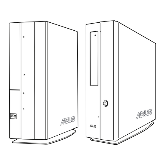
P2-P5G41/P4-P5G41 is an all-in-one barebone system with rich home is an all-in-one barebone system with rich home entertainment features. The system comes in a stylish casing and powered by an ASUS motherboard that supports the Intel Prescott, Smithfield, Cedarmill, Kentsfield, Conroe, Wolfdale, ®... - Page 13 Front panel of P4-P5G41 Front panel (open) Front panel (close) Hard disk drive (HDD) LED. This LED lights up when data is read from or written to the hard disk drive. Optical disk drive (ODD) bay cover. Front panel cover.
-
Page 14: Rear Panel
Rear panel The illustration below shows the rear panel of the P2-P5G41 and P4-P5G41. Rear panel Power connector. Voltage selector. This switch allows you to adjust the system input voltage according to the voltage supply in your area. If the voltage supply in your area is 100-127V, set this switch to 115V. -
Page 15: Expansion Slot
13. VGA port. This port connects to a VGA monitor or other VGA-compatible devices. 14. DVI port. This port is for any DVI-D compatible device. 15. Serial port. This port is for pointing devices or other serial devices. 16. Expansion slot. ASUS P2-P5G41/P4-P5G41... -
Page 16: Internal Components
Internal components The illustration below is the internal view of the ASUS P2-P5G41/P4-P5G41 when you remove the chassis cover. The installed components are labeled for your reference. 5.25 inch optical disk drive and ASUS motherboard 3.5 inch hard disk drive cage... - Page 17 Chapter 2 This chapter helps you power up the system and install drivers and utilities from the Support CD. ASUS P2-P5G41/P4-P5G41...
-
Page 18: Chapter 2: Starting Up
Installing an operating system The ASUS P2-P5G41/P4-P5G41 supports Windows XP / Vista Operating ® Systems (OS). Always install the latest OS version and corresponding updates to maximize the features of your hardware. • To ensure that the OS work properly, install the drivers included in the Support CD. -
Page 19: Support Cd Information
The contents of the Support CD are subject to change at any time without notice. Visit the ASUS website at www.asus.com for updates. 2.3.1 Running the Support CD Place the Support CD into the optical drive. -
Page 20: Drivers Menu
The Drivers menu shows the available device drivers if the system detects installed devices. Install the necessary drivers to activate the devices. ASUS InstALL - Installation Wizard for Anti-Virus and Drivers Utility Installs all of the drivers and anti-virus software using the installation wizard. -
Page 21: Utilities Menu
® documents in Portable Document Format (PDF). ASUS Update The ASUS Update utility allows you to update the motherboard BIOS in a Windows ® environment. This utility requires an Internet connection either through a network or an Internet Service Provider (ISP). -
Page 22: Manual Menu
The manuals are in Portable Document Format (PDF) format. Install the Adobe ® Acrobat Reader from the Utilities menu before opening a manual. ® 2.3.5 ASUS Contact information Click the Contact tab to display the ASUS contact information. Chapter 2: Starting up... -
Page 23: Other Information
The icons on the top right corner of the screen give additional information on the motherboard and the contents of the Support CD. Click an icon to display the specified information. Motherboard Info Displays the general specifications of the motherboard. Browse this CD Displays the Support CD contents in graphical format. ASUS P2-P5G41/P4-P5G41... - Page 24 Technical Support Form Displays the ASUS Technical Support Request Form that you have to fill out when requesting technical support. Filelist Displays the contents of the Support CD and a brief description of each item in text format. Chapter 2: Starting up...
-
Page 25: Asus Ai Manager
ASUS AI Manager ASUS AI Manager allows you to launch AI Disk, AI Security, and AI Probe easily. 2.4.1 Installing AI Manager To install AI Manager on your computer: Place the Support CD into the optical drive. The CD automatically displays the Drivers menu if Autorun is enabled on your computer. -
Page 26: Main
Click to switch between a full-screen AI Manager window and the Quick bar. Click to keep AI Manager in the taskbar. Click to close AI Manager. 2.4.4 Main Launch AI Disk, AI Security, or AI Probe from the Main menu. Click the small triangle to open or close the Main menu. -
Page 27: Ai Security
If you are using AI Security for the first time, key in a password consisting of up to 20 alphanumeric characters. Confirm your password. Key in your password hint (optional). Click OK. Select the device you want to lock, then click Apply. ASUS P2-P5G41/P4-P5G41 2-11... - Page 28 Key in your password, then click OK. The device you selected cannot be accessed without the password. To unlock a device: Deselect the device you locked, then click Apply. Key in your password, then click OK. To change your password, click Change Password and follow the onscreen instructions.
-
Page 29: My Favorites
My Favorites menu. Click Open. The application you selected is added and its icon appears. Right-click an icon in the My Favorites menu to open, delete, or rename the corresponding application. Double-click an icon to open the corresponding application. ASUS P2-P5G41/P4-P5G41 2-13... -
Page 30: Support
2.4.6 Support The Support menu displays links to the ASUS international website, online technical support website, online download support website, and contact information website. 2.4.7 Information The Information menu displays the general information of your system, motherboard, CPU, BIOS, memory, and other devices installed. - Page 31 Chapter 3 This chapter gives information about the motherboard that comes with the system. This chapter includes the motherboard layout, jumper settings, and connector locations. ASUS P2-P5G41/P4-P5G41...
-
Page 32: Chapter 3: Motherboard Info
Introduction The P2-P5G41/P4-P5G41 barebone system comes with an ASUS motherboard. This chapter provides technical information about the motherboard for future upgrades or system reconfiguration. Motherboard layout DEBUGPORT LED_CON CLRTC PWR_FAN SATA1 eNOVA Super MX-128 Intel ® ICH7 SATA2 VT6325 BUZZER... -
Page 33: Jumpers
If the steps above do not help, remove the onboard battery and move the jumper again to clear the CMOS RTC RAM data. After clearing the CMOS, reinstall the battery. CLRTC Normal Clear RTC (Default) P5Q8L P5Q8L Clear RTC RAM ASUS P2-P5G41/P4-P5G41... - Page 34 USB device wake-up (3-pin USBPW1-4, USBPW56) Set these jumpers to +5V to wake up the computer from S1 sleep mode (CPU stopped, DRAM refreshed, system running in low power mode) using the connected USB devices. Set these jumpers to +5VSB to wake up from S3 and S4 sleep modes (no power to CPU, DRAM in slow refresh, power supply in reduced power mode).
-
Page 35: Connectors
This connector is for a serial (COM) port. Connect the serial port module cable to this connector, then install the module to a slot opening at the back of the system chassis. COM1 PIN 1 P5Q8L P5Q8L COM Connector ASUS P2-P5G41/P4-P5G41... - Page 36 CPU Fan connector (4-pin CPU_FAN) The fan connector support cooling fans of 350mA~2000mA (24W max.). Connect the fan cable to the fan connector on the motherboard, ensuring that the black wire of each cable matches the ground pin of the connector. CPU_FAN P5Q8L P5Q8L CPU Fan Connector...
- Page 37 The system may become unstable or may not boot up if the power is inadequate. • Ensure that your power supply unit (PSU) can provide at least the minimum power required by your system. ASUS P2-P5G41/P4-P5G41...
- Page 38 Digital audio connectors (4-1 pin SPDIF_OUT, SPDIF_OUT1) These connectors are for additional Sony/Philips Digital Interface (S/PDIF) ports. Connect the S/PDIF Out module cables to these connectors, then install the modules to slots opening at the back of the system chassis. SPDIF_OUT SPDIF_OUT1 P5Q8L P5Q8L Digital Audio Connectors...
- Page 39 10. Optical drive audio-in connector (4-pin CD) This connector allows you to receive stereo audio input from sound sources such as a CD-ROM, TV tuner, or MPEG card. P5Q8L P5Q8L Internal Audio Connector ASUS P2-P5G41/P4-P5G41...
- Page 40 3-10 Chapter 3: Motherboard info...
- Page 41 Chapter 4 This chapter tells how to change the system settings through the BIOS Setup menus. Detailed descriptions of the BIOS parameters are also provided. ASUS P2-P5G41/P4-P5G41...
-
Page 42: Chapter 4: Bios Setup
ASUS CrashFree BIOS 3: Updates the BIOS using a floppy disk, USB flash disk, or the motherboard Support CD when the BIOS file fails or gets corrupted. ASUS EZ Flash 2: Updates the BIOS using a floppy disk or USB flash disk during POST. ASUS Update: Updates the BIOS in Windows environment. -
Page 43: Afudos Utility
Ensure that the floppy disk is not write-protected and has at least 1024KB free space to save the file. The BIOS screens in this sections are for reference only. The actual BIOS screens may not be the same as shown. ASUS P2-P5G41/P4-P5G41... - Page 44 Updating the BIOS file To update the BIOS using the AFUDOS utility: Download the latest BIOS file from the ASUS website at www.asus.com. Save the BIOS file to a bootable floppy disk. Write down the BIOS filename on a piece of paper. You need to key in the exact BIOS filename at the DOS prompt.
- Page 45 The utility verifies the file and starts updating the BIOS. A:\>afudos /iP5Q8L.ROM AMI Firmware Update Utility - Version 1.19(ASUS V2.07(03.11.24BB)) Copyright (C) 2002 American Megatrends, Inc. All rights reserved. WARNING!! Do not turn off power during flash BIOS Reading file ..done Reading flash ..
-
Page 46: Asus Crashfree Bios 3 Utility
4.1.3 ASUS CrashFree BIOS 3 utility The ASUS CrashFree BIOS 3 utility is an auto recovery tool that allows you to restore the BIOS file when it fails or gets corrupted during the updating process. You can update a corrupted BIOS file using the motherboard Support CD, a floppy disk, or USB flash disk that contains the updated BIOS file. -
Page 47: Recovering The Bios From The Support Cd
Restart the system after the utility completes the updating process. The recovered BIOS may not be the latest BIOS version for this motherboard. Visit the ASUS website at www.asus.com to download the latest BIOS file. Recovering the BIOS from a USB flash disk... -
Page 48: Asus Ez Flash 2 Utility
4.1.4 ASUS EZ Flash 2 utility The ASUS EZ Flash 2 feature allows you to update the BIOS without having to go through the long process of booting from a floppy disk and using a DOS-based utility. The EZ Flash 2 utility is built in the BIOS chip so it is accessible by pressing <Alt>... -
Page 49: Asus Update Utility
4.1.5 ASUS Update utility The ASUS Update is a utility that allows you to manage, save, and update the motherboard BIOS in Windows environment. The ASUS Update utility allows you ® • Save the current BIOS file; • Download the latest BIOS file from the Internet;... - Page 50 To update the BIOS through the Internet: Launch the ASUS Update utility from the Windows desktop by clicking Start ® > Programs > ASUS > ASUSUpdate > ASUSUpdate. The ASUS Update main window appears. Select Update BIOS from the Select the ASUS FTP site nearest...
- Page 51 To update the BIOS through a BIOS file: Launch the ASUS Update utility from the Windows desktop by clicking Start ® > Programs > ASUS > ASUSUpdate > ASUSUpdate. The ASUS Update main window appears. Select Update BIOS from a file option from the dropdown menu, then click Next.
-
Page 52: Bios Setup Program
The BIOS setup screens shown in this section are for reference purposes only. They may not exactly match what you see on your screen. • Visit the ASUS website at www.asus.com to download the latest BIOS file. 4-12 Chapter 4: BIOS setup... -
Page 53: Bios Menu Screen
At the bottom right corner of a menu screen are the navigation keys for that particular menu. Use the navigation keys to select items in the menu and change the settings. Some of the navigation keys differ from one screen to another. ASUS P2-P5G41/P4-P5G41 4-13... -
Page 54: Menu Items
4.2.4 Menu items BIOS SETUP UTILITY Main Advanced Power Boot Tools Exit Use [ENTER], [TAB] System Time [14:09:58] or [SHIFT-TAB] to The highlighted item on the menu bar System Date [Fri 03/20/2009] select a field. Use [+] or [-] to displays the specific items for that SATA1 :[Not Detected]... -
Page 55: Main Menu
Select Field General Help Save and Exit Exit v02.61 (C)Copyright 1985-2009, American Megatrends, Inc. 4.3.1 System Time [xx:xx:xx] Allows you to set the system time. 4.3.2 System Date [Day xx/xx/xxxx] Allows you to set the system date. ASUS P2-P5G41/P4-P5G41 4-15... -
Page 56: Sata 1/2
4.3.3 SATA 1/2 While entering Setup, the BIOS automatically detects the presence of SATA devices. There is a separate submenu for each SATA device. Select a device item then press <Enter> to display the SATA device information. SATA 1 Disabled: Disables LBA Mode. -
Page 57: Storage Configuration
Storage Configuration value for detecting ATA/ATAPI device(s). IDE Detect Time Out (Sec) [35] IDE Detect Time Out (Sec) [35] Selects the time out value for detecting ATA/ATAPI devices. Configuration options: [0] [5] [10] [15] [20] [25] [30] [35] ASUS P2-P5G41/P4-P5G41 4-17... -
Page 58: System Information
4.3.5 System Information This menu gives you an overview of the general system specifications. The BIOS automatically detects the items in this menu. Bios Information Version : 0209 Build Date : 02/09/09 Processor Type : Intel(R) Core(TM)2 CPU 6300 @ 1.86GHz Speed : 1866MHz System Memory... -
Page 59: Advanced Menu
Max CPUID Value Limit [Disabled] Select Screen Intel(R) Virtualization Tech [Enabled] Select Item CPU TM Function [Enabled] General Help Execute Disable Bit Capability [Enabled] Save and Exit Intel(R) SpeedStep(TM) Tech [Enabled] Exit v02.61 (C)Copyright 1985-2009, American Megatrends, Inc. ASUS P2-P5G41/P4-P5G41 4-19... - Page 60 Ratio CMOS Setting [Auto] Sets the ratio between CPU Core Clock and the FSB frequency. Configuration options: [Auto]. If an invalid ratio is set in CMOS then actual and setpoint values may differ. Key in ratio numbers directly. C1E Support [Enabled] Allows you to enable or disable Intel CPU Enhanced Halt (C1E) function, a CPU power-saving function in system halt state.
-
Page 61: Chipset
[Enabled, 32MB] GTT Graphics Memory Size [No VT mode, 2MB] DVMT Memory [256MB] Select Screen Select Item Protect Audio Video Path Mode [Disabled] Change Option General Help Save and Exit Exit v02.61 (C)Copyright 1985-2009, American Megatrends, Inc. ASUS P2-P5G41/P4-P5G41 4-21... - Page 62 Memory Remap Feature [Enabled] Enables or disables the remapping of overlapped PCI memory above the total physical memory. We recommend that you set this item to [Enabled] when you install 4GB memory. Configuration options: [Enabled] [Disabled] DRAM Frequency [Auto] Selects the DRAM frequency. Configuration options: [Auto] [667 MHz] [800 MHz] Configure DRAM Timing by SPD [Enabled] Allows you to enable or disable configurating DRAM Timing by SPD.
-
Page 63: Onboard Devices Configuration
[HD Audio]. Configuration options: [AC97] [HD Audio] Serial Port1 Address [3F8/IRQ4] Allows you to select the Serial Port1 base address. Configuration options: [Disabled] [3F8/IRQ4] [2F8/IRQ3] [3E8/IRQ4] [2E8/IRQ3] Onboard 1394 Controller [Enabled] Enables or disables the onboard 1394 controller. Configuration options: [Enabled] [Disabled] ASUS P2-P5G41/P4-P5G41 4-23... -
Page 64: Usb Configuration
4.4.4 USB Configuration The items in this menu allows you to change the USB-related features. Select an item then press <Enter> to display the configuration options. USB Configuration Options Options Module Version - 2.24.3-13.4 Disabled Enabled USB Devices Enabled: None USB Functions [Enabled] USB 2.0 Controller... -
Page 65: Pci Pnp
OS are transparently encrypted using Enova X-Wall MX AES 128-bit strength. Only your password is able to unlock your data. Real-time Disk Encrypt. Tech. [Press Enter] Press <Enter> to enable or disable the real-time disk encryption technology. ASUS P2-P5G41/P4-P5G41 4-25... -
Page 66: Power Menu
Power menu The Power menu items allow you to change the settings for the Advanced Power Management (APM). Select an item then press <Enter> to display the configuration options. BIOS SETUP UTILITY Main Advanced Power Boot Tools Exit Select the ACPI state Suspend Mode [Auto] used for System... -
Page 67: Apm Configuration
Enables or disables RTC to generate a wake event. When this item is set to [Enabled], the items RTC Alarm Date, RTC Alarm Hour, RTC Alarm Minute, and RTC Alarm Second appear with set values. Configuration options: [Disabled] [Enabled] ASUS P2-P5G41/P4-P5G41 4-27... -
Page 68: Hardware Monitor
4.5.5 Hardware Monitor BIOS SETUP UTILITY Power Hardware Monitor CPU Temperature CPU Temperature [23ºC/73ºF] MB Temperature [30ºC/86ºF] ºC/86ºF] ] CPU Fan Speed [4891RPM] Smart Q-FAN Function [Enabled] VCORE Voltage [1.344V] 3.3V Voltage [3.152V] 5V Voltage [4.838V] Select Screen 12V Voltage [11.712V] Select Item Change Field... -
Page 69: Boot Menu
Enter Go to Sub-screen The number of device items that appears on the screen depends on the number of General Help devices installed in the system. Configuration options: [Removable Dev.] Save and Exit Exit [Hard Drive] [ATAPI CD-ROM] [Disabled] ASUS P2-P5G41/P4-P5G41 4-29... -
Page 70: Boot Settings Configuration
Full Screen Logo [Enabled] Enables or disables the ASUS MyLogo2 feature. Configuration options: [Disabled] [Enabled] Set this item to [Enabled] to use the ASUS MyLogo2™ feature. AddOn ROM Display Mode [Force BIOS] Sets the display mode for option ROM. Configuration options: [Force BIOS]... -
Page 71: Security
<Enter> twice. The message Password uninstalle appears. If you forget your BIOS password, you can clear it by erasing the CMOS Real Time Clock (RTC) RAM. See section 3.3 Jumpers for information on how to erase the RTC RAM. ASUS P2-P5G41/P4-P5G41 4-31... -
Page 72: Change User Password
After you have set a supervisor password, the other items appear to allow you to change other security settings. <Enter> to change Security Settings password. <Enter> again to Supervisor Password : Installed disabled password. User Password : Installed Change Supervisor Password User Access Level [Full Access] Change User Password... -
Page 73: Tools Menu
(C)Copyright 1985-2009, American Megatrends, Inc. 4.7.1 ASUS EZ Flash 2 Allows you to run ASUS EZ Flash 2. When you press <Enter>, a confirmation message appears. Use the left/right arrow key to select between [Yes] or [No], then press <Enter> to confirm your choice. -
Page 74: Exit Menu
Exit menu The Exit menu items allow you to load the optimal or failsafe default values for the BIOS items, and save or discard your changes to the BIOS items. BIOS SETUP UTILITY Main Advanced Power Boot Tools Exit Exit Options Exit system setup after saving the Exit &... - Page 75 Manufacturer: ASUSTeK COMPUTER INC. Address, City: No.150, LI-TE RD., PEITOU, TAIPEI 112, TAIWAN R.O.C. Country: TAIWAN Authorised representative in Europe: ASUS COMPUTER GmbH Address, City: HARKORT STR. 21-23, 40880 RATINGEN Country: GERMANY...
Need help?
Do you have a question about the P4-P5G41 and is the answer not in the manual?
Questions and answers