Table of Contents
Advertisement
Quick Links
Advertisement
Table of Contents

Related Manuals for Magos SR Series


Summary of Contents for Magos SR Series
- Page 1 SR-Series User Manual...
-
Page 2: Table Of Contents
INSTALLATION procedure identification system overview SYSTEM DESCRIPTION 4. M ECHANICAL INSTALLATION Installation Restrictions and Limitations general installation guidelines ELECTRICAL INSTALLATION GUIDELINES Power Supply Interface 6. C OMMUNICATION NTERFACE Radar Manager Page 1 © Copyright 2017, Magos Systems. All Rights Reserved... - Page 3 Figure 1: Radar instalation height Figure 2: SR sensor outline and dimensions Figure 3: SR Tripod Installation Figure 4: SR Tripod adapter Figure 5: SR Wall Installation Figure 6: Wall mount Bracket Page 2 © Copyright 2017, Magos Systems. All Rights Reserved...
- Page 4 Figure 12: SR500 External operation cable Figure 13: Radar Manager Main Screen Figure 14: Radar Manager - Choosing a fixed IP Figure 16: Radar Manager - Choosing a fixed IP Page 3 © Copyright 2017, Magos Systems. All Rights Reserved...
-
Page 5: Introduction
ONTACTING AGOS UPPORT Support is available to customers who have a trial version of a Magos product or who have purchased a Magos product and have a valid maintenance contract. To contact Magos support, send an email to support@magosys.com. Page 4... -
Page 6: Scope
NSTALLATION PERSONNEL The SR Radar is designated for installation by technicians/system integrators who have received training by Magos Ltd. Only. It is not designated for the casual consumer or installation by “lay-men”. If you have not received proper training please contact Magos Ltd or visit our website (www.magosys.com) for a list of authorized installation personnel. -
Page 7: System Overview
It provides high accuracy, real-time location and speed data on detected targets. The SR series is a radar technology based sensor. This means that it transmits low power (less than 100mW) RF signal in the C-Band frequency and inspects the returned signal. -
Page 8: System Description
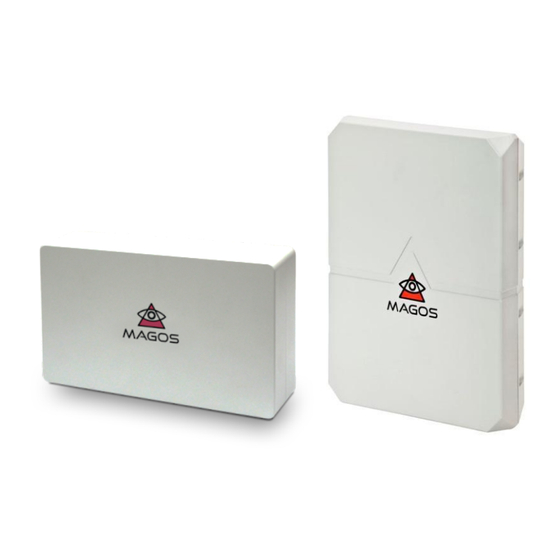
● Interface: Ethernet with POE according to IEEE 802.3at Type 1 (802.3af) and Type 2 ● Dimensions 9.8''(w) x 5.8''(h) x 2.3''(d) ● Weight: 3.3 Pounds ● IP67 ● 5.8/2.4FCC & CE compliant. Page 7 © Copyright 2017, Magos Systems. All Rights Reserved... - Page 9 Figure 2: SR sensor general view Page 8 © Copyright 2017, Magos Systems. All Rights Reserved...
-
Page 10: Echanical Installation
1° in azimuth and approximately 0.1m in range. ● As mentioned earlier the SR series might exhibit disturbances and "ghost" targets as a result of large returned signals. This occurs when a very large target (car/ truck etc.) moves in the vicinity of the radar (30m away or less, and 5m... -
Page 11: General Installation Guidelines
Holes are compatible to 1/4’’-20X1/2 screws. Screws and mounting brackets can be purchased separately from Magos. The brackets and their use are depicted in: Figure 3 and Figure 4 for installation on a tripod, or Figures 5-7 for wall/mast/pole mounted installation. - Page 12 Figure 3: SR sensor outline and dimensions Page 11 © Copyright 2017, Magos Systems. All Rights Reserved...
- Page 13 Figure 4: SR Tripod Installation Figure 5: SR Tripod adapter Figure 6: SR Wall Installation Page 12 © Copyright 2017, Magos Systems. All Rights Reserved...
- Page 14 Figure 8 and Figure 9 depict general rules of thumb for unit placement. It is strongly recommended that customers new to radar technology in general and the SR specifically would perform a Page 13 © Copyright 2017, Magos Systems. All Rights Reserved...
- Page 15 Ensure that sensor is level with the ground, otherwise sensor coverage area might be reduced depending on the sensor’s elevation angle coverage and the degree of tilt relative to the ground. Figure 11: Angle Coverage Page 14 © Copyright 2017, Magos Systems. All Rights Reserved...
- Page 16 Above 9m there might be a “dead-zone” in the vicinity of the sensor in accordance with the sensor’s elevation angle coverage. In order to achieve best performance refer to Table 1 and Figure 12 for recommended tilt angle. Page 15 © Copyright 2017, Magos Systems. All Rights Reserved...
- Page 17 Figure 13: Tilt Angle Height Range Tilt angle [meters] [meters] [degrees] Page 16 © Copyright 2017, Magos Systems. All Rights Reserved...
- Page 18 Connecting to the sensor: use outdoor weather immune cables. When cable is not plugged in use the connector cap to maintain weather immunity. Magos is not responsible to weather damage (corrosion etc.) caused by using improper cables/failure to the use the cap when not installed. In such cases product warranty is void.
- Page 19 Page 18 © Copyright 2017, Magos Systems. All Rights Reserved...
-
Page 20: Electrical Installation Guidelines
Electrical installation of the sensor consists of a simple cable connection on the radar side. Figure 13 contains the electrical schema of this cable. For safety and warranty reasons users must use only cables supplied by Magos. Users must also ensure that that connector shielding on the RJ45 connector side is properly grounded. - Page 21 Page 20 © Copyright 2017, Magos Systems. All Rights Reserved...
-
Page 22: Communication Interface
OMMUNICATION NTERFACE The SR sensor supports standard ethernet interface (standart 100Mbps). The product label contains it’s unique MAC address. When interfacing Magos propritery MASS C&C software consult with the MASS user manual for more details on sersor interface and ICD. - Page 23 This IP will be retained in flash memory on the radar and will not be erased upon reset. It can be re-configured using the radar manager tool whenever needed. Figure 17: Radar Manager - Choosing a fixed IP Page 22 © Copyright 2017, Magos Systems. All Rights Reserved...
- Page 24 Page 23 © Copyright 2017, Magos Systems. All Rights Reserved...
-
Page 25: Bit
HW or other faults that might result in reduced sensor performance or even prevent operation of the sensor. Note – The BIT feature is not support in all FW versions. In order to find out whether your sensor support BIT please contact Magos support team. 7.1 BIT M ECHANISM The built-in test contains 2 types of tests –... -
Page 26: Handling Failed Bit Reports
Note I – This test is only support in specific HW models that include the Tamper Switch. Contact Magos support to find out whether your unit includes this feature. Note II – Once tamper switch is set it can only be cleared by an authorized Magos technician. 7.3 H... -
Page 27: Warnings And Disclaimers
3. Mechanical installation of the SR500 is not within the scope of responsibility of Magos. Magos is not liable to any damage incurred to the customer and/or to a third party due to faulty installation (loose bolting/weak brackets etc). -
Page 28: Industry Canada Compliance
The product warranty is automatically voided if: You or anyone else use the product or attempt to use it other than as specified by Magos; ● The fault/defect in your product is the result of a voltage surge subjected to the product either ●... -
Page 29: Limitation Of Liability
Protection Laws which cannot be excluded, Magos’ liability for any breach of that guarantee, condition or warranty is limited to: (i) in the case of a supply of goods. Magos doing any one or more of the following: replacing the goods or supplying equivalent goods; repairing the goods paying the cost of replacing the goods or of acquiring equivalent goods;... - Page 30 Page 29 © Copyright 2017, Magos Systems. All Rights Reserved...
-
Page 31: Appendices
Magos strongly recommends using a Surge Protection device together with PoE switches to operate Magos Radars. Disclaimer: Prices are based on estimation only, Magos is in no way partnered with any one of the manufacturer listed below and does not provide it with the Magos Radar 9.1.1 R... - Page 32 4 port PoE switch $300 Redlion Unmanaged 10/100BaseT(X) RJ45 PoE support for 4 ports 1001T-4POE 5 port PoE+ switch Phoenix $440 Unmanaged 10/100BaseT(X) RJ45 Contact PoE+ support for 4 ports Page 31 © Copyright 2017, Magos Systems. All Rights Reserved...
- Page 33 Industrial 8 PoE + 2 GbE / FE $800 Korenix SFP Booster PoE Switch 3810f JetNet6728 Industrial 28G Full Gigabit Managed PoEPlus Ethernet $5000 Korenix Switch JetNet 7014G Industrial 10GbE/TX, 4 $2600 Korenix GbE/SFP Managed Switch Page 32 © Copyright 2017, Magos Systems. All Rights Reserved...
- Page 34 9.1.3 SCHEMATIC NETWORK C ONNECTION Page 33 © Copyright 2017, Magos Systems. All Rights Reserved...
Need help?
Do you have a question about the SR Series and is the answer not in the manual?
Questions and answers