
Related Manuals for DoorHan DCUH-2


Summary of Contents for DoorHan DCUH-2
-
Page 1: Table Of Contents
General Information Safety Rules Design Installation Electrical Connections Programming Control Unit Operation Troubleshooting Appendix DCUH-2/3 Control Unit for Electro- Hydraulic Dock Leveler with Hinged Lip Owner’s Manual © DoorHan, 01.2020... -
Page 2: General Information
1. GENERAL INFORMATION DCUH-2, DCUH-3 control units operate electro-hydraulic was halted in the event of a potential emergency or if pow- dock levelers with hinged lip of DLHH/DLHHI series. er supply failed. The units are equipped with an uncontrolled movement... -
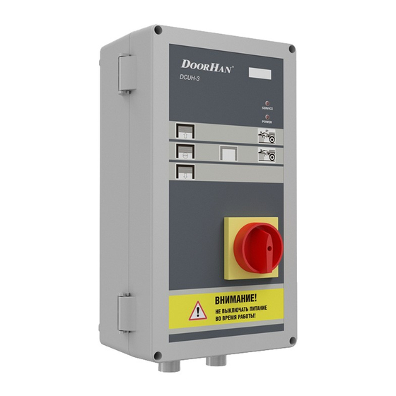
Page 3: Design
3. DESIGN Fig. 3.1. Closed view 1. Menu screen (LCD display) 6. Main power switch 2. Service indicator 7. Inflatable dock shelter control button 3. Power indicator 8. Door CLOSE button 4. Dock leveler parking button (P) 9. Door STOP button 5. -
Page 4: Installation
4. INSTALLATION Mount the control unit so the distance between control unit bottom and dock floor is approximately 1–1,5 m. Choose the fasteners corresponding to the type of wall. Fig. 4.1. Control unit installation Anchor points... -
Page 5: Electrical Connections
5. ELECTRICAL CONNECTIONS WARNING! Before performing electrical connection of the control unit disconnect all electric power and ensure it won’t be sup- plied during the work. Fig. 5.1. Electrical connections diagram ELECTROMAGNETIC VALVE COIL IN 1 220 V +24V IN 2 GREEN +24V IN 3... - Page 6 Fig. 5.2. 380–415 V mains connection ELECTROMAGNETIC VALVE COIL IN 1 +24V IN 2 GREEN +24V IN 3 GREEN +24V IN 4 +24V CLOSE CLOSE STOP STOP OPEN OPEN 6,3 A 6,3 A View А 6,3 A DOCK SHELTER MOTOR ~380 - 415 V 0,55 kW Fig.
- Page 7 Fig. 5.3. Connection of lip inductive position sensor (part number: 1747-22) IN 3 +24V IN 4 black blue brown +24V CLOSE CLOSE STOP STOP OPEN OPEN TERMINALS ON OPERATOR CONTROL BOARD Fig. 5.4. Connection of photoelectric end switch IN 1 +24V IN 2 +24V...
-
Page 8: Programming
DIP 4 is not used DIP 4 is not used Menu screen shows dH2 Menu screen shows dH3 In DCUH-2 mode each operation of the door and dock leveler is displayed on the menu screen accordingly (see Ta- ble 6.1.2). - Page 9 Table 6.1.2. LCD display indication in DCUH-2 mode Dock equipment Menu screen message Operation Leveler rising Dock leveler Leveler lowering In DCUH-3 mode each operation of the door and dock leveler is displayed on the menu screen accordingly (see Ta- ble 6.1.3).
- Page 10 Table 6.2.2. Parameters of the DCUH-3 programming menu Message Setting option Description Parameter value 1–9 — 3–11 sec. Time period in which hydro station motor stops during leveler 1. UH Default value — 7 sec. raising Change of value by 1 equals 1 sec. Parameter value 1–9 —...
-
Page 11: Control Unit Operation
7. CONTROL UNIT OPERATION 7.1. TO RAISE THE LEVELER 1. Park the transport vehicle with an open body in front 4. Make sure the power led on the control unit is lit, then of the leveler so that it is positioned squarely against press the RAISE button. -
Page 12: Appendix
APPENDIX. RECOMMENDED SPARE PARTS Fig. 1. Control unit design Table 1. Spare parts for the control unit Part name Part number DCUH-2 main board PCB_DCUH2-M/V.1.1 DCUH-3 main board PCB_DCUH3-M/V.1.1 DCUH-2 control board PCB_DCUH2-BT/V.1.0 DCUH-3 control board PCB_DCUH3-BT/V.1.0 Switch assembly DCU007 Table 2. - Page 16 We very much appreciate that you have chosen the product manufactured by our company and believe that you will be satisfied with its quality. For information on purchasing, distribution and servicing contact DoorHan central office at: 120 Novaya street, Akulovo village, Odintsovo district, Moscow region, 143002, Russia Phone: +7 495 933-24-00 E-mail: info@doorhan.com...
Need help?
Do you have a question about the DCUH-2 and is the answer not in the manual?
Questions and answers