
Related Manuals for DoorHan PE200B


Summary of Contents for DoorHan PE200B
-
Page 1: Table Of Contents
Design Installation Electrical Connections 0,75 kW Electrical Connections 1,5 and 2,2 kW Control Unit Setting Door Operation Parameters Error codes Control Unit for High-Speed Door of SPEEDROLL/ SPEEDFOLD series with DOORHAN SERVO Drive Installation and Operation Manual © DoorHan, 08.2021... -
Page 2: General Information
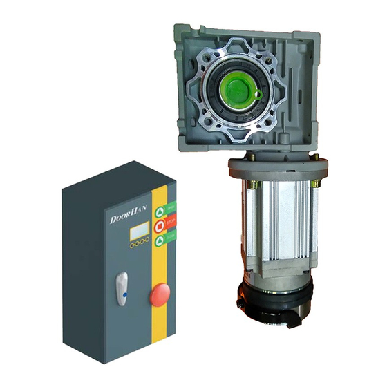
1. GENERAL INFORMATION Control units of PE200B, PE500B, PE700B series are designed to operate high-speed PVC doors of SPEEDROLL/SPEED- FOLD series. Carefully read through the present instructions prior to connecting and setting the control unit. Table 1. Specifications Parameters PE200B... -
Page 3: Installation
Mount the control unit so the distance between control unit bottom and dock floor is approximately 1,2–1,5 m. Choose the fasteners corresponding to the wall type. 4. ELECTRICAL CONNECTIONS 0,75 KW Table 2. Description of ports' functions of 0,75 kW control unit, part no. PE200B(C) Port Function Description... - Page 4 4.1. ELECTRICAL CONNECTIONS DIAGRAMS Fig. 3. Connection of photocells, part no. HSDC 18201 (0,75 kW) Table 3. Connection of photocells (0,75 kW) Port Function Wire colour DC 24 В + Brown and pink Com/Gnd Blue Black (change contact type to NC: set – 6668 > advanced settings > contact Safety device 2 type >...
- Page 5 Fig. 5. Internal motor encoder (0,75 kW) Fig. 6. External absolute encoder (0,75 kW)
- Page 6 Table 5. Connection of motor brake (0,75 kW) Port Function Wire colour Blue * DoorHan does not provide a power wire. Wirecolour may differ from those listed in the manual. It is recommended to use a wire with a cross section of 1,5 mm...
- Page 7 Table 7. Connection of signal lamp or siren 24 V (0,75 kW) Description Install a jumper on terminals 25 and 26 Connect lamp to terminals 24 and 27* * DoorHan does not provide a power wire. It is recommended to use a wire with a cross section of 0,75 mm...
- Page 8 Fig. 11. Magnetic loop connection, part no. LOOP-2 (0,75 kW)* Loop 1 The inductive loop should be made of insulated copper wire with minimum cross section of 1,5 mm The feeder shall be made of the same but twisted material (minimum 10 turns per 300 mm). Set the AUTO mode and select the required auto-closing time to ensure correct operation of the unit.
- Page 9 Fig. 12. Button connection, part no. DKH009 (0,75 kW) Fig. 13. Key switch connection, part no. KEYSWITCH (0,75 kW) Note. The buttons whose connection diagrams are shown in Fig. 12 and 13, allow you to open and close the door without using the main controls.
- Page 10 Set the AUTO mode and select the required auto-closing time to ensure correct operation of the unit. * DoorHan does not provide a power wire. It is recommended to use a wire with a cross section of 0,75 мм . Wirecolour may differ.
- Page 11 Fig. 16. RB61 safety edge connection, part no. 180-589 (0,75 kW) Table 9. Safety edge connection (0,75 kW) Port Function Wire colour DC 24 В + Com/Gnd White and black Safety input 1 Yellow WARNING! Prior to safety edge connecting take off the cover from the module. Make sure the yellow wire is connected to the NO contact.
- Page 12 Fig. 17. Connection of DHRE-1 external radio receiver (0,75 kW) Note. Connect the control signal to contact 17 or 20, depending on the desired logic of operation. The programming of the receiver is carried out in accordance with the installation and operation instructions of the DHRE-1(2) external radio receiver. Fig.
- Page 13 Fig. 19. Connection of Photocell-N photocell (0,75 kW)* Table 10. Connection of Photocell-N photocell (0,75 kW) Port Function Safety device 1 DC 24 B+ Drill technological holes for the electrical cable (0,75 mm for each core) in the photocell racks (0,5). Place the photocells at the top of each rack and secure them tightly.
- Page 14 Door (B) will not open while door (A) is open and vice versa. * DoorHan does not provide a power wire. It is recommended to use a wire with a cross section of 0,75 mm...
-
Page 15: Electrical Connections 1,5 And 2,2 Kw
5. ELECTRICAL CONNECTIONS 1,5 AND 2,2 KW Table 12. Description of ports' functions of 1,5 and 2,2 kW control units (part no. PE500(C) and PE700B(C) respectively) Port Function Description AC 220/240 V, input Braking resistor, output+ Braking resistor, input - Motor brake + DC 24 V Motor brake -... - Page 16 5.1. ELECTRICAL CONNECTIONS DIAGRAMS Fig. 21. Connection of photocells, part no. HSDC 18201 (1,5 and 2,2 kW) Table 13. Connection of photocells (1,5 and 2,2 kW) Port Function Wire colour Black (change contact type to NC:set – 6668 > advanced settings > contact Safety device 2 type >...
- Page 17 Fig. 23. Internal motor encoder (1,5 and 2,2 kW) Fig. 24. External absolute encoder (1,5 and 2,2 kW)
- Page 18 Table 15. Connection of motor brake (1,5 and 2,2 kW) Port Function Wire colour Blue * DoorHan does not provide a power wire. Wirecolour may differ from those listed in the manual. It is recommended to use a wire with a cross section of 2,5 мм...
- Page 19 Table 17. Connection of signal lamp or siren 24 V (1,5 and 2,2 kW) Description Install a jumper on terminals 21 and 22 Connect lamp to terminals 20 and 23* * DoorHan does not provide a power wire. It is recommended to use a wire with a cross section of 0,75 мм...
- Page 20 Fig. 29. Magnetic loop connection, part no. LOOP-2 (1,5 and 2,2 kW)* The inductive loop should be made of insulated copper wire with minimum cross section of 1,5 мм The feeder shall be made of the same but twisted material (minimum 10 turns per 300 mm). Set the AUTO mode and select the required auto-closing time to ensure correct operation of the unit.
- Page 21 Fig. 30. Button connection, part no. DKH009 (1,5 and 2,2 kW) Fig. 31. Key switch connection, part no. KEYSWITCH (1,5 and 2,2 kW) Note. The buttons whose connection diagrams are shown in Fig. 30 and 31, allow you to open and close the door without using the control unit.
- Page 22 Set the AUTO mode and select the required auto-closing time to ensure correct operation of the unit. * DoorHan does not provide a power wire. It is recommended to use a wire with a cross section of 0,75 мм . Wirecolour may differ.
- Page 23 Fig. 34. RB61 safety edge connection, part no. 180-589 (1,5 and 2,2 kW) Table 19. Safety edge connection (1,5 and 2,2 kW) Port Function Wire colour Safety device 1 Yellow Com/Gnd White and black DC 24 В + WARNING! Prior to safety edge connecting take off the cover from the module. Make sure the yellow wire is connected to the NO contact.
- Page 24 Fig. 35. Connection of DHRE-1 external radio receiver (1,5 and 2,2 kW) Note. Connect the control signal to contact 13 or 15, depending on the desired logic of operation. The programming of the receiver is carried out in accordance with the installation and operation instructions of the DHRE-1(2) external radio receiver. Fig.
- Page 25 5.3 INSTALLATION OF PHOTOCELL-N PHOTOCELLS Fig. 37. Connection of Photocell-N photocells (1,5 and 2,2 kW) Table 20. Connection of Photocell-N photocells (1,5 and 2,2 kW) Port Function Safety device 1 DC 24 В+ Drill technological holes for the electrical cable (0,75 mm for each core) in the photocell racks (0,5). Place the photocells at the top of each rack and secure them tightly.
- Page 26 Fig. 38. Layout of racks for SPEEDROLL / SPEEDFOLD door Control unit 1500 1500 PHOTOCELL-N (4 pcs.) SPEEDROLL / SPEEDFOLD 5.3.1. Setting the receiving part of the Photocell-N photocells Install the jumper on the NO/NC contacts from the NC position to the NO position according to Fig. 40. Fig.
- Page 27 5.4. CONNECTION DIAGRAM OF TRAFFICLIGHT-LED TRAFFIC LIGHT Fig. 41. Connection of TRAFFICLIGHT-LED 220 V (1,5 and 2,2 kW) Table 21. Connection of TRAFFICLIGHT-LED 220 V (1,5 and 2,2 kW) № Description Install a jumper on terminals 25 and 26 and connect to contact 2 Connect the traffic light to contact 24 for red light, and to contact 27 for green light.
-
Page 28: Control Unit Setting
6. CONTROL UNIT SETTING 6.1. SET THE MANUAL MODE 6.2. CHOOSE THE LIMIT SENSOR SERVO SERVO MODE MODE STATUS STATUS info Mode info Mode 1.1. Press 1.1. Press Mode 1.2. The display will show 1.2. The display will show Password Password 6666 6666... - Page 29 6.3. CHECK THE DIRECTION OF DOOR 6.4. ADJUST DOOR TRAVEL LIMITS CURTAIN ROTATION 1.1. The display will show 1.1. The display will show Press Open-Key Open Limit Direction Correct 1.2. Press the OPEN button on the control unit To set the UPPER travel limit: 1.3.
- Page 30 6.5. SET THE PHOTOCELLS SERVO 1.9. Press MODE Choose Safety 2 STATUS 1.10. Press info Mode The display will show 1.1. Press Safety 2 1.2. The display will show Password Save 6666 1.11. Press choose N.C Press then Save 1.3.
- Page 31 6.7. OPENING SPEED ADJUSTMENT 1.11. The display will show SERVO MODE 1. Opening speed STATUS info Mode 1.1. Press Save 1.12. Press 1.2. The display will show Password to set the desired value 6666 1.13. Press Save 1.3.
- Page 32 6.8. CLOSING SPEED ADJUSTMENT SERVO 1.7. Press MODE The display will show STATUS Closing speed info Mode 1.1. Press The display will show Save Password 1.8. Press 6666 to set the desired value 1.9. Press Save 1.2.
- Page 33 6.9. PARTIAL OPENING ADJUSTMENT SERVO 1.7. Press MODE The display will show STATUS Partial opening info Mode 100 % 1.1. Press The display will show Save Password 1.8. Press 6666 to set the desired value: 10–100 % 1.9. Press Save 1.2.
- Page 34 6.10. ANTI-FROZEN RUNNING MODE ADJUSTMENT 1.8. Press SERVO MODE to set the desired value in minutes. To disable the function — OFF. STATUS info Mode 1.9. Press Save 1.1. Press The display will show 6.11. RESET TO FACTORY SETTINGS Password SERVO 6666 MODE...
- Page 35 6.12. CONNECTION OF SIGNAL LAMP AND SIREN 1.11. The display will show SERVO Output 1 config MODE Running STATUS Save info Mode 1.12. Press 1.1. Press 1.2. The display will show choose Running or any of the following parameters* Password 1.13.
- Page 36 6.13. SETTING THE ADV PARAMETER SERVO 1.7. Press MODE to choose 7779 STATUS 1.8. Press info Mode Change the index value to 83* 1.1. Press ADV Parameter The display will show Index: 83 Password 6666 1.9. Press Change the parameter value from 0 to 1 1.2.
- Page 37 6.14. SETTING THE AUTOMATIC CLOSING TIME 1.8. Press – SERVO MODE to set the desired value STATUS 1.9. Press Save info Mode 1.10. Press 1.1. Press to enter the main menu The display will show Password 6.15. SETTING THE MAINTENANCE PERIOD 6666 SERVO MODE...
- Page 38 6.16. SET THE HEIGHT OF PHOTOCELLS ACTUATION 1.10. The display will show SERVO MODE Set current height as Safety 1 Height disabled STATUS info Mode 1.1. Press Set the height of the door curtain to 10 cm from 1.2. The display will show the floor level for Safety 1 Password 1.11.
- Page 39 6.17. SET THE CONNECTION OF THE TRAFFIC LIGHT TO THE PE500B CONTROL UNIT 1.11. The display will show SERVO Output 2 config MODE Running STATUS Save info Mode 1.12. Press 1.1. Press choose Non-open Limit 1.2. The display will show 1.13.
- Page 40 6.18. INTERLOCK. SETTING THE PE500B CONTROL UNIT 1.11. The display will show SERVO Output 4 config MODE Running STATUS Save info Mode 1.12. Press 1.1. Press choose Double Interlock* 1.2. The display will show 1.13. Press Save Password 1.14. The display will show 6666 1.
- Page 41 6.19. INTERLOCK. SETTING THE PE200B CONTROL UNIT 1.11. The display will show SERVO Output 2 config MODE Running STATUS Save info Mode 1.12. Press 1.1. Press choose Double Interlock* 1.2. The display will show 1.13. Press Save Password 1.14. The display will show 6666 1.Opening speed...
-
Page 42: Door Operation Parameters
7. DOOR OPERATION PARAMETERS Table 23. Door parameters and their settings Parameter Value Factory Setting by Default Opening speed 10–125 Closing speed 10–125 Slowdown when opening 30–70 Slowdown when closing 30–70 • Disabled Automatic closing time 5 sec • 1–120 sec •... - Page 43 Table 24. Error codes and required actions (cont'd) Error Code Code Description Reason/Required Action ERR15 Connection failure Default or change the PCB ERR16 Brake failure Only in history memory • Check the resistor ERR18 Brake failure • Check the resistor wiring •...
- Page 44 For information on purchasing, distribution and servicing contact DoorHan central office at: 120 Novaya street, bld.1, Akulovo village, Odintsovo district, Moscow region, 143002, Russia Phone: +7 495 933-24-00 E-mail: info@doorhan.com...
Need help?
Do you have a question about the PE200B and is the answer not in the manual?
Questions and answers