Central Machinery METAL CUTTING BANDSAW 93762 Set Up And Operating Instructions Manual
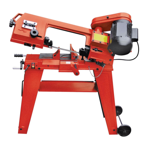
Horizontal/vertical metal cutting bandsaw
Hide thumbs
Also See for METAL CUTTING BANDSAW 93762:
- Assembly and operating instructions manual (34 pages) ,
- Owner's manual & safety instructions (28 pages)
Table of Contents
Advertisement
horizontal/vertical
metal cutting bandsaw
set up and operating instructions
visit our website at: http://www.harborfreight.com
read this material before using this product.
Failure to do so can result in serious injury.
save this manual.
Copyright
2006 by Harbor Freight Tools
©
contained herein may be reproduced in any shape or form without the express written consent of Harbor
Freight Tools. Diagrams within this manual may not be drawn proportionally. Due to continuing improve-
ments, actual product may differ slightly from the product described herein. Tools required for assembly
and service may not be included.
For technical questions or replacement parts, please call 1-800-444-3353.
Revised Manual 11h
model
93762
. All rights reserved. No portion of this manual or any artwork
®
Advertisement
Chapters
Table of Contents

Related Manuals for Central Machinery METAL CUTTING BANDSAW 93762


Summary of Contents for Central Machinery METAL CUTTING BANDSAW 93762
- Page 1 Failure to do so can result in serious injury. save this manual. Copyright 2006 by Harbor Freight Tools © contained herein may be reproduced in any shape or form without the express written consent of Harbor Freight Tools. Diagrams within this manual may not be drawn proportionally. Due to continuing improve- ments, actual product may differ slightly from the product described herein.
-
Page 2: Table Of Contents
... 3 general tool saFetY warnings ... 3 band saw saFetY warnings ... 5 vibration saFetY ... 7 grounding instructions ... 7 grounded tools: tools with three prong plugs ... 7 double insulated tools: tools with two prong plugs ... -
Page 3: Important Safety Information
save this manual Keep this manual for the safety warn- ings and precautions, assembly, operat- ing, inspection, maintenance and cleaning procedures. Write the product’s serial number in the back of the manual near the assembly diagram (or month and year of purchase if product has no number). - Page 4 DON’T FORCE TOOL. It will do the job better and safer at the rate for which it was designed. USE RIGHT TOOL. Don’t force tool or attachment to do a job for which it was not designed. recommended minimum wire gauge For eXtension cords (120 volt) eXtension cord...
-
Page 5: Band Saw Safety Warnings
Saw Blade to stop it. Wear heavy-duty work gloves when changing the Saw Blade. Turn off the Bandsaw and allow the Saw Blade to completely stop if the Saw Blade is to be backed out of an uncompleted cut. Page 5... - Page 6 Industrial applications must follow OSHA guidelines. Maintain labels and nameplates on the tool. These carry important safety information. If unreadable or miss- ing, contact Harbor Freight Tools for a replacement. Avoid unintentional starting. Prepare to begin work before turning on the tool.
-
Page 7: Vibration Safety
ditions and situations that may occur. It must be understood by the operator that common sense and caution are factors which cannot be built into this product, but must be supplied by the operator. vibration safety This tool vibrates during use. Re- peated or long-term exposure to vibration may cause temporary or permanent physical injury, particularly... -
Page 8: Double Insulated Tools: Tools With Two Prong
Improper connection of the equip- ment-grounding conductor can re- sult in a risk of electric shock. The conductor with insulation having an outer surface that is green with or without yellow stripes is the equip- ment-grounding conductor. If repair or replacement of the electric cord or plug is necessary, do not connect the equipment-grounding conductor to a live terminal. -
Page 9: Specifications
31 and 32 are included. If any parts are missing or broken, please call Harbor Freight Tools at the number shown on the cover of this manual as soon as possible. -
Page 10: To Attach The Bandsaw To The Stand
to attach the bandsaw to the stand: stand (top view) mounting hole mounting hole mounting hole mounting hole screw (59) spring washer (58) Flat washer (57) Figure b With additional manpower, and an adequate lifting device, carefully set the Bandsaw on top of the Stand as- sembly, making sure the upper sec- tion of the Stand fits outside the base of the Bandsaw. -
Page 11: To Attach The Pulley Cover
to attach the pulley cover: worm shaFt (9) heX bolt (76) Flat washer (77) bodY Frame (60) Figure d Position the Pulley Cover (72) over the Worm Shaft (9) and Motor Shaft (81). Align the mounting hole in the Pulley Cover with the mounting hole in the Body Frame (60). -
Page 12: To Convert The Bandsaw For Vertical Use
Medium support plate (150) Small Large motor pulleY Raise the Saw Head to its full verti- cal position, making sure it locks in small position by turning the Support Plate medium (150) to the right until it firmly locks large into the Body Frame (60) and insert- ing the Locking Pin (153). - Page 13 Remove the two Screws (190), and remove the Small Vertical Cutting Plate (194). (see Figure i.) Guide the Saw Blade (82) through the slot in the Vertical Cutting Plate (189), and secure it in position with the two Screws (190).
-
Page 14: Operating Instructions
operating instructions caution! Turn the Power Switch (164) to its “oFF” position and un- plug the tool from its electrical outlet prior to making adjustments to the tool. to use the vise: Raise the Body Frame (60) to its vertical position, and lock the Body Frame in place with the Support Plate (150) and Locking Pin (153). -
Page 15: Adjustments
100, 104) adjustment is a critical fac- tor in the performance of the Band- saw. It is always best to try a new Saw Blade (82) to see if it will correct poor cutting before attempting to adjust the Blade Guide Bearings. For example,... -
Page 16: Tension
(54) lower screw (22) Turn the Blade Tension Adjusting Knob (34) clockwise to increase ten- sion on the Saw Blade (82). Turn the Blade Tension Adjusting Knob coun- terclockwise to decrease tension on the Saw Blade. Correct tension is... -
Page 17: Adjusting The Feed Rate
When the Bandsaw is not in use over long periods of time, release the ten- sion on the Saw Blade (82). adjusting the Feed rate: Figure Q The feed rate of the Body Frame (60) can be adjusted by turning the Han-... -
Page 18: Basic Bandsaw Operation
(60) stand (not included) with a larger support workpiece. plate (150) Allow the Saw Blade (82) to turn up to full speed before feeding the work- piece into the Saw Blade. (see Figure s.) warning! Keep hands and fingers safely away from the cut- ting area. -
Page 19: Basic Bandsaw Operation
Blade (82) tension or machine vi- bration. If this is found, turn off the Bandsaw and correct the problem before using. (see Figure t.) Allow the Saw Blade (82) to turn up to full speed before feeding the Saw bodY Frame (60) vise assY. - Page 20 (see Figure t.) SKU 93762 For technical questions, please call 1-800-444-3353. Wait until the Saw Blade (82) comes to a complete stop. Next, raise the Body Frame (60) to its full vertical position, making sure it locks in place by turn- ing the Support Plate (150) to the right until it firmly locks into the Body Frame.
-
Page 21: Inspection, Maintenance, And Cleaning
Locking Pin (153). (see Figure s.) Release Saw Blade (82) tension by turning the Blade Tension Knob (34). (see Figure u.) Slip the old Saw Blade (82) off the Upper Blade Wheel (37), Lower Blade Wheel (54), and Guide as- semblies. (see Figure u.) -
Page 22: V-Belt
Place the new Saw Blade (82) be- tween each of the Guide assemblies and around the Upper Blade Wheel (37) and Lower Blade Wheel (54). important: the teeth must be pointing downward toward the motor. (see Figure u.) note: The Bandsaw is equipped with a 64”... - Page 23 Saw. do not immerse any electrical part of the machine in any liquids. pivot (120)
-
Page 24: Troubleshooting
troubleshooting SKU 93762 For technical questions, please call 1-800-444-3353. Page 24... -
Page 25: Parts List
part # description Spindle Pulley Socket Head Screw(M8x8) Screw(M4x8) Flat Washer(4) Flat Washer(5) Screw(M4x8) Seal Cover Oil Seal(B15x35x7) Bearing(6202Z) Spacer Bearing(6202Z) Worm V-Belt Hex Bolt(M6x16) Spring Washer(6) Flat Washer(6) Gear Box Cover Gear Box Gasket Key(C5x28) Gear Pin(5x26) Gear Shaft Hex Bolt(M8x30) Hex Bolt(M8x16) Hex Bolt(M8x30) - Page 26 part # description Motor Pulley Key(C5x28) Motor Blade Blade Guide Bracket Seat Flat Washer(16) Spring Washer(8) Hex Bolt(M8x30) Spring Washer(8) Bearing(180029) Balde Guide Bracket Shaft Bearing(180029) Ring(9) Blade Guard Screw(M6x16) Spring Washer(8) 100 Hex Bolt(M8x30) 101 Spring Washer(8) 102 Falt Washer 103 Bearing(180029) 104 Pin 105 Balde Guide Bracket...
- Page 27 part # description 163 Shaft 164 Cable Protector 165 Switch Panel 165-1 Switch Box 166 Screw(M3.9x30) 167 Pull Relief 168 Power Cord 168-1 Serrated Washer(5) 168-2 Bolt 168-3 Terminal 168-4 Rubber 168-5 Metal Plate 169 Power Switch 170 Angle Scale 171 Rivet 172 Lead Screw Support 173 Flat Washer(6)
-
Page 28: Assembly Diagram
assemblY diagram 194: Vertical Cutting Plate Support Not Shown. note: Some parts are listed and shown for illustration purposes only, and are not available individually as replacement parts. REV 09f SKU 93762 For technical questions, please call 1-800-444-3353. Page 28... - Page 29 90 daY warrantY Harbor Freight Tools Co. makes every effort to assure that its products meet high quality and durability standards, and warrants to the original purchaser that this product is free from defects in materials and workmanship for the period of 90 days from the date of purchase.
Need help?
Do you have a question about the METAL CUTTING BANDSAW 93762 and is the answer not in the manual?
Questions and answers
I need part number 177 lead screw
The lead screw (part number 177) is listed in the manual for the Central Machinery METAL CUTTING BANDSAW 93762. However, it is noted that some parts are shown for illustration purposes only and are not available individually as replacement parts. Therefore, the availability of part number 177 cannot be confirmed.
This answer is automatically generated
part number # 20 worm gear (23 tooth)
The replacement part number for the 23 tooth worm gear for the Central Machinery Metal Cutting Bandsaw 93762 is 53.
This answer is automatically generated