Table of Contents
Advertisement
T T T T T ABLE SA
ABLE SA
ABLE SA
ABLE SA W - 10 INCH
ABLE SA
ASSEMBLY AND OPERATING INSTRUCTIONS
3491 MISSION OAKS BLVD., CAMARILLO, CA 93011
VISIT OUR WEB SITE AT HTTP://WWW.HARBORFREIGHT.COM
Copyright © 2004 by Harbor Freight Tools
this manual or any artwork contained herein may be reproduced in any shape
or form without the express written consent of Harbor Freight Tools.
For technical questions and replacement parts, please call 1-800-444-3353
W - 10 INCH
W - 10 INCH
W - 10 INCH
W - 10 INCH
DIRECT DRIVE
DIRECT DRIVE
DIRECT DRIVE
DIRECT DRIVE
DIRECT DRIVE
91815
®
. All rights reserved. No portion of
Advertisement
Table of Contents

Related Manuals for Central Machinery 91815


Summary of Contents for Central Machinery 91815
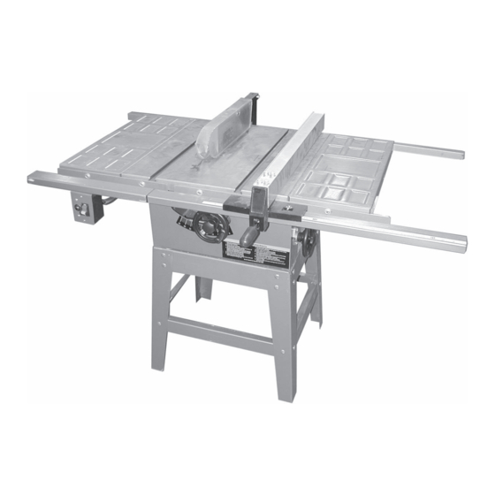
- Page 1 W - 10 INCH DIRECT DRIVE DIRECT DRIVE DIRECT DRIVE DIRECT DRIVE DIRECT DRIVE 91815 ASSEMBLY AND OPERATING INSTRUCTIONS 3491 MISSION OAKS BLVD., CAMARILLO, CA 93011 VISIT OUR WEB SITE AT HTTP://WWW.HARBORFREIGHT.COM Copyright © 2004 by Harbor Freight Tools ®...
-
Page 2: Specifications
Keep bystanders, children, and visitors away while operating a power tool. Distractions can cause you to lose control. Protect others in the work area from debris such as chips and sparks. Provide barriers or shields as needed. SKU 91815 Page 2... -
Page 3: Electrical Safety
Power Switch on, invites accidents. 13. Remove adjusting keys or wrenches before turning the power tool on. A wrench or a key that is left attached to a rotating part of the power tool may result in personal injury. SKU 91815 Page 3... - Page 4 25. When servicing a tool, use only identical replacement parts. Follow instructions in the “Inspection, Maintenance, And Cleaning” section of this manual. Use of unauthorized parts or failure to follow maintenance instructions may create a risk of electric shock or injury. SKU 91815 Page 4...
- Page 5 19. Never cut more than one piece of stock at a time, for any type of cut. 20. Provide proper support for the stock based on its size and the type of operation to be performed. SKU 91815 Page 5...
- Page 6 30. Keep extension cord off the ground and away from water. Note: Performance of this tool may vary depending on variations in local line voltage. Exten- sion cord usage may also affect tool performance. SKU 91815 Page 6...
-
Page 7: Grounded Tools: Tools With Three Prong Plugs
The plug must be connected to a properly grounded outlet. If the tool should electrically malfunction or break down, grounding provides a low resistance path to carry electricity away from the user, reducing the risk of electric shock. (See Figure A.) SKU 91815 Page 7... -
Page 8: Double Insulated Tools: Tools With Two Prong Plugs
(See Table A.) If you are using one extension cord for more than one tool, add the nameplate amperes and use the sum to determine the required minimum cord size. (See Table SKU 91815 Page 8... - Page 9 3.5 – 5.0 5.1 – 7.0 7.1 – 12.0 12.1 – 16.0 16.1 – 20.0 * Based on lim iting the line voltage drop to five volts at 150% of the rated am peres. SYMBOLOGY Table B SKU 91815 Page 9...
-
Page 10: Stand Assembly
5/8” Carriage Bolts (61), 5/16” Flat Washers (59), 5/16” Lock Washers (39), and 5/16” Hex Nuts (58). The longer Cross Braces must be under the longer Stand Top pieces as shown below. Figure C. Stand Assembly SKU 91815 Page 10... -
Page 11: Assembling The Saw To The Stand
With the help of another person, carefully lift and turn the saw over onto the Stand feet. Level the saw body by moving it back and forth until the saw body is sitting level and squarely on the Stand feet. Securely tighten all Stand hardware. Figure D. Stand-to-Saw Assembly SKU 91815 Page 11... -
Page 12: Extension Wing Assembly
Bolts when the (corner) lead edge of the wing is also flush with the Table from front to back. Repeat steps one through four with the left Extension Wing (76). Left Extension Wing (76) Right Extension Wing (76) Figure E. Wing Assembly Figure F. Wing and Rail Assembly SKU 91815 Page 12... - Page 13 On the short Rear Rail (21), push up as far as it will go, then tighten the bolt holding it to the Table. Do not tighten the bolts from the Rear Rails to the Extension Wings at this time. Figure G. Guide Rail Assembly SKU 91815 Page 13...
- Page 14 Securely tighten the hardware on the front of the Extension Wing. Move the straight edge to the rear of the Table and Extension Wing and repeat steps 2 and 3. Repeat steps 1 through 4 on the Table and left Extension Wing. SKU 91815 Page 14...
-
Page 15: Fence Assembly And Alignment
Attach the Rear Hook (35) and Sliding Pad (36) to the rear of the Fence (37) using one 1/4” Flat Washer (2), 1/4” Lock Washer (14), and two Hex Nuts (12). See Figure H, above. Place the Fence (37) on the Table (22) Guide Rail, adjacent to the miter fixture slot. SKU 91815 Page 15... - Page 16 Loosen Hex Nut (32) at the end of Shaft (33). Place an accurate straight edge against the Saw Blade (flat surface, not teeth) and the Splitter (27). Move the Splitter until it aligns (center-to-center) with the Saw Blade. Retighten Hex Nut (32). SKU 91815 Page 16...
-
Page 17: Miter Gauge Adjustment
Flange (113). Note that the teeth should be facing the front of the Table Saw. Replace the Arbor Flange (102) and the Arbor Nut (101). Place a length of wood in back of the Saw Blade so that at least one of the teeth engage the wood. SKU 91815 Page 17... -
Page 18: Adjusting 45 And 90 Degree Positive Stops
Turn the Set Spacer in the desired direction. Retighten the Set Screw (150) when the Set Spacer (162) stop is adjusted correctly with the Saw Blade at 45 degrees. 10. Replace the Table Insert (8) and two Screws (7). SKU 91815 Page 18... -
Page 19: Controls And Indicators
Fence and the Saw Blade. And, the thinner width is to the left of the Saw Blade. This lowers the chance of binding and kickback. Longer stock needs to have external support at the same height as the Table. SKU 91815 Page 19... -
Page 20: Making A Cross Cut
Saw Blade, never cross over the Saw Blade. When the cut is complete, step back and press the Switch down to the Off position. 10. When the Saw Blade stops turning, remove the stock from the Table. SKU 91815 Page 20... -
Page 21: Inspection, Maintenance, And Cleaning
CENSED TECHNICIANS AND NOT BY THE BUYER. THE BUYER ASSUMES ALL RISK AND LIABILITY ARISING OUT OF HIS OR HER REPAIRS TO THE ORIGINAL PRODUCT OR REPLACEMENT PARTS THERETO, OR ARISING OUT OF HIS OR HER INSTALLATION OF REPLACEMENT PARTS THERETO. SKU 91815 Page 21... - Page 22 Switch Box Lock Washer Round Head Screw M4X8 Washer Screw Cord Clamp Guide Washer Tap Screw M5X10 NOTE: Some parts are listed and shown for illustration purposes only and are not available individually as replacement parts. SKU 91815 Page 22...
- Page 23 SAW BODY AND STAND ASSEMBLY DRAWING SKU 91815 Page 23...
-
Page 24: Motor And Trunnion Assembly Parts List
Arbor Wrench Motor Housing Hex Socket Cap Screw M5X20 Carbon Brush Brush Cap Hex Socket Cap Screw M5X16 NOTE: Some parts are listed and shown for illustration purposes only and are not available individually as replacement parts. SKU 91815 Page 24... - Page 25 MOTOR AND TRUNNION ASSEMBLY DRAWING SKU 91815 Page 25...
Need help?
Do you have a question about the 91815 and is the answer not in the manual?
Questions and answers