Advertisement
Quick Links
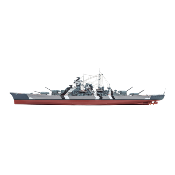
Your 1:200 scale model of the legendary battleship Bismarck is packed with
intricate details which precisely replicate every aspect of this state-of-the-
art warship. Each piece has been created using premium quality materials to
bring maximum enjoyment during your complete build.
STAGE 117: ROTATION MOTOR FOR THE
THIRD 38CM GUN TURRET
STAGE 118: FITTING THE STERN
STAGE 119: THE AFT CIRCUIT BOARD
STAGE 120: THE TWO OUTER PROPELLERS
STAGE 121: THE CENTRAL PROPELLER
STAGE 122: THE GEARBOX FOR THE
PROPELLERS
© 2020 Hachette Partworks Ltd.
North America Edition by Agora Models
Pack 11 | Build Instructions
In your eleventh model pack, you will assemble:
STAGE 123: THE TWIN RUDDERS
STAGE 124: THE AFT ANCHOR AND MOTOR
STAGE 125: MAINMAST AND FOUR AA GUNS
STAGE 126: THE EIGHTH UPPER DECK SECTION
STAGE 127: LAST SECTION OF THE UPPER DECK
STAGE 128: THE FOURTH 38CM GUN TURRET
Advertisement

Related Manuals for Agora Models Bismarck


Summary of Contents for Agora Models Bismarck
- Page 1 Pack 11 | Build Instructions Your 1:200 scale model of the legendary battleship Bismarck is packed with intricate details which precisely replicate every aspect of this state-of-the- art warship. Each piece has been created using premium quality materials to bring maximum enjoyment during your complete build.
- Page 2 Not suitable for children under the age of 14. This product is not a toy and is not designed for use in play. Keep the parts out of the reach of small children. Some parts may have sharp edges. Please handle them with care. AGORAMODELS BISMARCK...
- Page 3 117-03 117-02 COMPONENTS CHECKLIST 117-01: Motor PWB: Three 2.3 x 5mm PWB screws 117-02: 117-03: Cable label . FITTING THE MOTOR 117-01 117-03 117-01 Place the motor on your worktop. Remove the cable label 117-03 from its backing. AGORAMODELS BISMARCK...
- Page 4 117-01 shaft of the motor , as indicated. 117-02 117-01 117-02 When the cog is fitted onto 117-01 the shaft of the motor , push it down as far as possible. 117-01 117-02 AGORAMODELS BISMARCK...
- Page 5 112-09 teeth of cog 117-01 Fix the motor in place using 117-01 screws. 99-01 Completed work The motor for rotating the third 38cm gun turret has been fitted to the underside of the deck of the aft superstructure. AGORAMODELS BISMARCK...
- Page 6 118-01 the hull. Take the stern 115-01 fit it against the keel section the central screw hole on the edge of the stern fits beneath the screw hole on the keel section, as indicated. AGORAMODELS BISMARCK...
- Page 7 116-02 section (arrows). Fit the connector in place as shown. 116-02 118-03 118-03 Fix the starboard connector 118-01 the stern and the hull section 116-02 using two screws. 116-02 118-01 118-03 AGORAMODELS BISMARCK...
- Page 8 Fix the port connector to the 118-01 116-01 stern and the hull section 116-01 using two screws. 118-02 118-01 Completed work The final section of the metal hull assembly has been fixed in place at the stern of the model. AGORAMODELS BISMARCK...
-
Page 9: Take A Break
THE AFT CIRCUIT BOARD 119-01 COMPONENTS CHECKLIST 119-01: Circuit board . TAKE A BREAK! Completed work There is no assembly work in this stage. 119-01 The circuit board will be fitted beneath the aft superstructure in the 119-01 next stage. AGORAMODELS BISMARCK... - Page 10 ) in support brackets so that you can motor through the bracket in the centre of the upper access the underside of the upper deck. Take care not deck structure, as indicated by the arrow. to damage any of the parts already in place. AGORAMODELS BISMARCK...
- Page 11 Take the circuit board and position it on the Fix the circuit board in place using four upper deck in the orientation shown. Ports 11 and 12 2 x 6mm screws. are on the left in this photo (circled in white). AGORAMODELS BISMARCK...
- Page 12 4-07 18-01 18-02 18-01 18-02 Take the tester box and the battery Connect the tester cable to port 11 (circled) on 4-07 119-01 . Check that the switch on the the circuit board battery box (circled) is off. AGORAMODELS BISMARCK...
- Page 13 The two turrets swivel. Press the button again to end the test. When fully rotated, the guns may pause for a few seconds before re-starting. NOTE: Choose a suitable elevation for the gun barrels before starting the test (red dotted arrow). AGORAMODELS BISMARCK...
- Page 14 S4 button again. Completed work The aft superstructure electronics have been connected and tested. After completing the tests, turn off the battery box and carefully remove the tester cable from port 11 of the aft circuit board. AGORAMODELS BISMARCK...
- Page 15 Take the brackets the port side of the keel section . Fix in place 120-03 (marked L and R) from the frame . You with two 2 x 4mm screws, as shown. will also need four 2 x 4mm screws. AGORAMODELS BISMARCK...
- Page 16 Working from inside the hull, fix the support 120-02 so that the flat side is against the hull and slide it for the propeller in place with two 111-01 forwards, against the opening in keel section 2 x 4mm screws AGORAMODELS BISMARCK...
- Page 17 Pull the ends of the propeller shafts At the same time, the fine metal sleeves on the 120-02 forwards as far as possible along the channels shafts (indicated by the arrows) should be pushed in the keel section (arrows). aft as far as possible. AGORAMODELS BISMARCK...
- Page 18 Fit the support for the propeller (indicated by From inside the hull, fix the support for the propeller 115-04 121-02 115-01 the arrow) against the opening in part to the keel section using a 2 x 4mm screw, as shown. AGORAMODELS BISMARCK...
- Page 19 Attach the cable label (D2) to the cable of 121-01 the motor for the propellers near the The three propellers have been fitted to the hull. connector, as shown. The propeller motor will be fitted in the next stage. AGORAMODELS BISMARCK...
-
Page 20: Preparatory Work
Fix the port cog housing to the keel section 120-01 111-01 of the port propeller shaft , fitting it onto the using two 2 x 4mm screws. 111-01 two raised screw sockets on the keel , as shown. AGORAMODELS BISMARCK... - Page 21 Similarly, fix the starboard gearbox support in the hull using three 2 x 4mm screws. in place in the starboard side of the hull using three 2 x 4mm screws. (In this photograph, the hull is viewed from the other side.) AGORAMODELS BISMARCK...
- Page 22 Take one of the grips, , from frame 122-12 , fix it in place with a 2 x 3mm screw. position it on the cog housing, over the pivot pin 122-12 . Fix in place with two 2 x 4mm screws. AGORAMODELS BISMARCK...
- Page 23 122-12 111-02 opening in part . Fix in place with a 2 x 3mm Fix it to the connector with two 2 x 4mm screw. screws. After fitting, check that the propellers can rotate freely. AGORAMODELS BISMARCK...
-
Page 24: Assembling The Gearbox
122-04 122-09 gearbox . Push it down so the end fits into hole in cog 122-09 the hole in cog AGORAMODELS BISMARCK... - Page 25 122-16 122-17 Fit cog on the left-hand cog shaft Fit the short cog shaft into the central hole 122-05 122-07 Finally, the third cog is fitted on the left-hand of cog (fitted on the motor). 122-14 cog shaft AGORAMODELS BISMARCK...
- Page 26 2 x 3 2 x 6 122-04 Completed work The three propeller shafts have been fitted to pivot pins and connected to the gearbox. Cogs and shafts connect the propeller motor to the propeller shafts. AGORAMODELS BISMARCK...
- Page 27 118-01, as indicated. Note section 118-01. the position of the three ribs: rib 1 (on the inside of the hull) sits between the ribs 2 and 3 on the cog. AGORAMODELS BISMARCK...
- Page 28 118-01. Make sure the ribs are aligned correctly, so that 123-04 123-03 of the hull. Note that with the cogs the rib on the inside of the hull is between the ribs on in the correct positions, the rudders are parallel. the cog. AGORAMODELS BISMARCK...
- Page 29 You may find that the fit of the motor is a bit wobbly. 123-02 123-03 teeth of cog interlock with the cogs This will be fixed in a later stage. 123-04. AGORAMODELS BISMARCK...
- Page 30 124-14: Shaft (longer) . ASSEMBLING THE GEARBOX FOR THE AFT ANCHOR 124-03 Place the right-hand side of the gear 124-13 124-03 housing on your worktop. 124-13 Insert the shorter shaft into the socket in the housing, as shown. AGORAMODELS BISMARCK...
- Page 31 Apply a little glue to the hub to hold the ring in place. AGORAMODELS BISMARCK...
- Page 32 Take the anchor motor and attach 124-03 124-05 124-16 housing . The cog of the reel the cable label (D-7) to the cable near the 124-07 engages with the large cog connector, as shown. AGORAMODELS BISMARCK...
- Page 33 124-11 124-10 anchor head . The shank is inserted from below, at the top of the anchor shaft , as shown. pushing the eyelet on the end of the shank through the hole first. AGORAMODELS BISMARCK...
- Page 34 Completed work Take the anchor assembly 124-12 fit the ring into the last link of the anchor The motor and gears for the aft anchor have been 124-09 cable , as shown. assembled and fitted inside the hull. AGORAMODELS BISMARCK...
- Page 35 . Carefully . Bend the tabs up at right angles. The lower remove all four parts from the frame. tab on part is bent twice at right angles (forwards and upwards) to form a U shape (arrow). AGORAMODELS BISMARCK...
- Page 36 When you are happy with the fit, glue the mast tip 125-08 frame . Very carefully, bend the central prong in place, as shown. upwards, at right angles to the two arms. Check the fit on the upper end of mainmast section AGORAMODELS BISMARCK...
- Page 37 (on the left in this photo) is beneath that they are correctly orientated, noting the position 125-11 the spar support . Glue the platform in place. of the holes (arrows). Glue the parts together, as shown. AGORAMODELS BISMARCK...
- Page 38 Take the signal lamp support and the signal lamp 125-01 125-02 section of the mainmast . Glue the two tabs from the frame . Check how the parts fit to the mast. together, as shown, and glue the signal lamp in place. AGORAMODELS BISMARCK...
- Page 39 Place the aft superstructure on your worktop. Identify Check the fit and then glue the mainmast 94-01 94-01 the hole on the central hangar where the to the central hangar , as shown. Note the 125-01 mainmast fits. position of the ladders. AGORAMODELS BISMARCK...
- Page 40 Make sure you have them in the central hangar. When they are correctly aligned, correct position, then glue in place. glue them in place. AGORAMODELS BISMARCK...
- Page 41 The other two anti-aircraft guns fit on the starboard side of the aft superstructure. Do not use The mainmast and four heavy anti-aircraft guns any glue – the guns need to rotate. have been fitted to the aft superstructure. AGORAMODELS BISMARCK...
- Page 42 The skylight from frame fits in the adjacent 126-01 how it fits in the slight recess in the upper deck recess of the upper deck section . Glue in place, 126-01 section . Glue in place. as shown. AGORAMODELS BISMARCK...
- Page 43 . Glue in 126-01 place, as shown. The two loading practice machines from frame 126-03 are glued in place in the last two recesses near the front edge of the upper deck section 126-01 , as shown. 126-01 AGORAMODELS BISMARCK...
- Page 44 126-01 126-01 section , as shown. The remaining six depth charges 126-04 from frame are glued to the port side of the aft superstructure on upper deck 99-01 section , as shown. 99-01 AGORAMODELS BISMARCK...
- Page 45 102-02 126-07 The railing forms a 126-06 continuation to railing : pegs on the lower edge are glued into holes in 102-01 126-07 102-01 the deck covering and the 102-02 superstructure deck , as shown. 126-06 102-02 AGORAMODELS BISMARCK...
- Page 46 Glue them in place in the holes 102-01 102-01 in the deck covering 102-02 the superstructure deck 126-08 102-02 126-06 Completed work Various details have been fitted to the upper deck section. Railings have been fitted around the superstructure. AGORAMODELS BISMARCK...
- Page 47 Separate one of the skylights from glue them in place at the forward end of the upper 127-02 126-01 the frame and glue it in place between the deck section , as shown. two larger skylights fitted in the previous stage. AGORAMODELS BISMARCK...
- Page 48 127-01 deck section . Glue the anchor chain holder depth charge racks. They are mirror images of each in line with it and the handwheel on top of other, as shown above. part , as shown. AGORAMODELS BISMARCK...
- Page 49 Glue the two electric capstans made with parts from 127-05 two rope drums , and two parts of the capstan head frame in place at the forward edge of the aft 127-01 , as shown. upper deck section , as shown. AGORAMODELS BISMARCK...
- Page 50 . Bend 102-01 the deck covering on the other side of the gun the handrails upwards and twist the steps to create two turret, in a similar way. ladders that are mirror images of each other, as shown. AGORAMODELS BISMARCK...
- Page 51 Glue in place, as shown. Details have been added to the two aft deck sections, and they have been fixed together. Four ladders have been fitted to the aft superstructure. AGORAMODELS BISMARCK...
- Page 52 Have some superglue ready. AGORAMODELS BISMARCK...
- Page 53 128-05 128-14 , so that the shaped edges match. Have the and push it through so that the wide end of 128-10 128-10 128-14 clutch shaft ready. part is flush with the edge of the ring AGORAMODELS BISMARCK...
- Page 54 Fit the lower part of the motor mounting 128-07 128-07 . Make sure that the cables on the circuit board the upper part . Fix the parts together using 128-01 of the motor are in the direction shown screws. (arrow). AGORAMODELS BISMARCK...
- Page 55 NOTE: the recesses around the opening on the upper deck. The two AA guns shown in steps 1 and 2 will be fitted in a future stage. AGORAMODELS BISMARCK...
- Page 56 Attach the cable label (D2) to the cable of fitted into the upper deck. Two 121-01 the motor for the propellers near the washers have been inserted to give the connector, as shown. rudder motor a better fit. AGORAMODELS BISMARCK...
Need help?
Do you have a question about the Bismarck and is the answer not in the manual?
Questions and answers