Table of Contents
Advertisement
Quick Links
Advertisement
Table of Contents

Related Manuals for Agora Models FERRARI 312 T4


Summary of Contents for Agora Models FERRARI 312 T4
- Page 1 FERRARI T H E L E G E N D A RY 1 9 7 0 F 1 F E R R A R I PAC K SCALE...
-
Page 2: Table Of Contents
FERRARI SCALE Contents STAGE 93 RIGHT BELLY SKIRT AND © Agora Models BULKHEAD ............1 STAGE 94 LEFT SIDE BODYWORK INNER COVERING ............5 WARNING: NOT SUITABLE FOR CHILDREN UNDER THE STAGE 95 AGE OF 14. THIS PRODUCT IS RIGHT SIDE BODYWORK INNER NOT A TOY AND IS NOT ............ -
Page 3: Right Belly Skirt And Bulkhead
312 T4 PACK 11 RIGHT BELLY SKIRT AND BULKHEAD THIS STAGE PROVIDES THE PARTS TO COMPLETE AND CLOSE THE RIGHT BELLY. ASSEMBLY OF THESE PARTS WILL BE SIMILAR TO THE LEFT SIDE OF THE MODEL. type P screws LIST OF PARTS LIST OF PARTS Right skirt Right bulkhead... - Page 4 ADVANCED TECHNI QUE FASTENING POINTS FOR THE SKIRT AND RIGHT BELLY BULKHEAD The images show the points for joining and fixing the skirt (A, B, C) and the bulkhead (D, E, F, G) to the right belly. base base base 93-01 Take the model and the right...
- Page 5 93-02 Position the skirt so that the fastening holes match with the screw seats. 93-03 Insert and tighten a type P screw in the 93-04 Insert and tighten a type P screw into first hole (A) in the front. the second hole (B). 93-05 Now take the bulkhead...
- Page 6 93-06 Slot it in so that the four fastening points (D, E, F, G, shown on page 2) all match. Press down gently until the covering snaps into place. Final result The right side of your model now looks like this. In the next stage In the next stage Left inner covering.
-
Page 7: Left Side Bodywork Inner Covering
312 T4 PACK 11 LEFT SIDE BODYWORK INNER COVERING IN THIS STAGE YOU WILL PREPARE AND ARRANGE THE CABLES AND LINES ON THE RIGHT SIDE OF THE COCKPIT SO THEY ARE TIDIED AWAY, AND USE TAPE TO KEEP THE SEATBELTS ON THE SEAT. THIS IS TO SIMULATE THE WEIGHT OF THE BUCKLES HOLDING THE BELTS DOWN. - Page 8 94-01 Place the model on your work surface. Note the seatbelts, which are slightly raised against the surface of the seat. 94-02 Take a strip of two-sided tape and apply it to the work surface. Cut two strips 4–5 mm wide and approx.
- Page 9 94-06 Use tweezers to remove the black line from the right dashboard indicator. 94-07 After laying out the line, starting from the gearbox, fix a strip of silver tape to the top part of the tank, then around the line and on the upright part, cockpit side.
- Page 10 94-10 Cut a strip of two-sided tape 2 mm wide and 5 mm long. Place the two- sided tape in the recess above the third air funnel trumpet. 94-11 Now place the cable joint onto the two-sided tape and press it down. This will keep the line in the correct position.
-
Page 11: Right Side Bodywork Inner Covering
NOW YOU’LL PREPARE AND ARRANGE THE CABLES AND LINES ON THE LEFT SIDE OF THE COCKPIT SO THEY ARE TIDIED AWAY. YOU WILL ALSO REARRANGE SOME SHORT SECTIONS OF THE LINES, TO MAKE YOUR 1:8 SCALE FERRARI 312 T4 EVEN MORE REALISTIC. type H screws LIST OF PARTS... - Page 12 95-01 Place the model on your work surface. 95-02 Slide it from under the transparent tube Use tweezers to remove the clear tube from of the radiator (circled). Connect the tube back the dashboard indicator. to the dashboard using a pair of tweezers. 95-03 Gently pull both clear tubes so that they are both in line, without making any loops...
- Page 13 95-06 Disconnect the two clear tubes from the oil filter couplings, pass them under the roll-bar tie-rods and under the cables of the distributor wires. Cut a 13 mm long section from the tube, then a second, longer 33–35 mm section. Now reconnect the tubes to the same connections you...
- Page 14 95-10 Cut a strip of two-sided adhesive 95-11 Now place the cable tape, 2 mm wide and 10–12 mm long. Use joint over the two-sided tape tweezers to place the double-sided tape and press. This will hold the over the recess above the third air horn. cable in the correct position.
-
Page 15: Right Wing Mirror
312 T4 PACK 11 RIGHT WING MIRROR NOW YOU’LL ASSEMBLE THE RIGHT WING MIRROR, WHICH YOU WILL BE ABLE TO FIT TO YOUR NEARLY COMPLETE MODEL AT A LATER STAGE. LIST OF PARTS LIST OF PARTS Cowling Support Mirror F E R R A R I 3 1 2 t4 Pa c k 1 1 . - Page 16 96-01 Set out the parts of the wing mirror on your work surface: (left to right) mirror, support, and cowling. 96-02 On one side, the mirror has a reflective surface, while on the other, there is a layer of two-sided tape. 96-03 The shaped form of the cowling matches the shape of...
- Page 17 96-04 You can try placing the mirror into the cowling without the two-sided tape in order to test the fitting. 96-05 Lift the film from the double-sided tape and remove it with the help of tweezers. 96-06 Position the mirror inside the cowling.
- Page 18 96-07 Take the support and fix it to the cowling, using its pin as shown. Final result You have finished building the right wing mirror. Carefully set it to one side. In the next stage In the next stage Parts of the left wing mirror. F E R R A R I 3 1 2 t4 Pa c k 1 1 .
-
Page 19: Left Wing Mirror
312 T4 PACK 11 LEFT WING MIRROR NEXT YOU’LL BUILD THE LEFT WING MIRROR, IN THE SAME WAY AS THE RIGHT ONE FROM THE PREVIOUS STAGE. LIST OF PARTS LIST OF PARTS Cowling Support Mirror F E R R A R I 3 1 2 t4 Pa c k 1 1 . - Page 20 97-01 Set out the parts of the wing mirror on your work surface: (left to right) cowling, support, and mirror. 97-02 As before, the mirror has a reflective surface, while on the other side there is a layer of two-sided tape. The cowling is shaped to accomodate the mirror.
- Page 21 97-04 Position the mirror inside the cowling. The two- sided tape will hold it in place. 97-05 You can remove the clear film protecting the reflective surface of the mirror, or wait until the build is completely finished. 97-06 Now take the support and fix it to the...
- Page 22 97-07 The circular and rectangular pegs highlighted here will secure the mirror to the bodywork, which will be supplied with stage 100. 97-08 Both mirrors have these fastening elements. These photos show you a preview where they will be mounted on the bodywork.
-
Page 23: Cockpit Windscreen
312 T4 PACK 11 THE COCKPIT WINDSCREEN STAGE 98 CONTAINS AN ESSENTIAL PART TO COMPLETE THE DRIVER’S EQUIPMENT. THE INSTRUCTIONS IN THE NEXT THREE STAGES RELATE TO THE BODYWORK, WE RECOMMEND READING FROM HERE THROUGH TO STAGE 100, THEN RETURNING TO THIS STAGE WITH ALL THE PARTS READY FOR ASSEMBLY. - Page 24 98-01 This stage begins the instructions that will add detail to and complete the bodywork of the model. Gather the parts from stages 98, 99 and 100 along with the inner coverings (stages 94 and 95) and the wing mirrors (stages 96 and 97), as shown in the image above.
- Page 25 98-05 Take two flanged type H screws and tighten them fully in the relevant fixing holes. 98-06 Now position the left inner covering (stage 94) and fit it in the bodywork, following the same steps as for the right covering. 98-08 ...
- Page 26 98-09 Press the two hooks into the recess until they are fitted in place. 98-10 Take the hooks (stage 100) and align them with the bodywork, making sure they are facing the right way as shown. In the next stage In the next stage The radiator air vents.
-
Page 27: Side Radiator Mesh Sections
312 T4 PACK 11 SIDE RADIATOR MESH SECTIONS THIS STAGE PROVIDES THE SIDE MESH SECTIONS THAT SERVE AS AN OUTLET FOR HOT AIR FROM THE FRONT SIDE RADIATORS OF THE COCKPIT. YOU’LL CONTINUE THE ASSEMBLY OF THE BODYWORK FROM THE PREVIOUS STAGE. - Page 28 99-01 Take the six white hooks which are trapezoidal in shape with one wider end and a more tapered one. Place three hooks on the right of the bodywork with their narrow ends facing the direction of travel as shown. 99-02 Press the three hooks into place, using the relevant 99-03 Fit the other three hooks on the left side...
- Page 29 99-04 Align the left and right radiator mesh on the sides of the bodywork as shown. You can see that the right mesh (on the left in the photo, arrow) is smaller than the left one. 99-06 Use these pins to fit the left radiator mesh to the bodywork.
- Page 30 99-07 In the same way, secure the smaller mesh on the right side to the bodywork. 99-08 This is how the bodywork of your model should look after the mesh sections have been fitted. In the next stage In the next stage Hooks, decals, and bodywork.
-
Page 31: Bodywork, Hooks, And Decals
312 T4 PACK 11 BODYWORK, HOOKS, AND DECALS AFTER COMPLETING THE ONE HUNDREDTH STAGE, YOU CAN FIT YOUR 1:8 SCALE MODEL WITH ITS BODYWORK. FOLLOW THE INSTRUCTIONS AND THE ACCOMPANYING IMAGES CAREFULLY. type B screws LIST OF PARTS LIST OF PARTS Screws Bodywork Decals... - Page 32 Summary PREVIOUSLY ASSEMBLED PARTS This is a short summary for the assembly of the bodywork from the previous stages. The assembly of the inside coverings and rear hooks (A, B and C) was described in stage 98; the assembly session for stage 99 was dedicated to the assembly of the air vents and the six white side hooks (D, E and F).
- Page 33 100-01 Place the model on your work surface. 100-02 Fit the bodywork onto the model. First of all, check the correct coupling with the rear brake ducts. F E R R A R I 3 1 2 t4 Pa c k 1 1 . s ta g e 1 0 0...
- Page 34 100-03 Pass the medical air pipe over the horizontal upright. Before proceeding, make sure that the body cover is properly in place around the whole model. 100-04 100-05 Gently rest the model on its left wheels. Use a In the same way, tighten a type B screw into Phillips screwdriver to drive a type B screw into the bottom rear hole of the right belly.
-
Page 35: First Rain Tyre
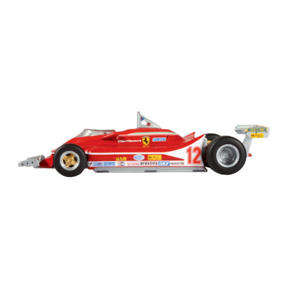
100-06 Fix the bodywork on the left side using two type B screws. 100-07 Take the two mirrors assembled in stages 96 and 97. Each mirror has a cylindrical peg and a square one. This latter peg is not perfectly central, which makes it easier to distinguish the left and right mirrors. - Page 36 MORE I NFO DIFFERENT RACE NUMBERS FOR EACH GP Stage 100 contains the decals with the numbers “1” and “2” of number 12 in the “filled” and “hollow” versions. The choice of which numbers to use is up to you. The vehicle reproduced in this model is the one with the 041 chassis that Gilles Villeneuve drove in the following races in 1979, with different types of number on the nose.
- Page 37 100-08 Identify the square and the round holes for securing the mirrors on the bodywork. 100-09 Press the mirrors onto the bodywork to secure them. 100-10 Carefully fit the windscreen glass, inserting the five assembly pegs into the holes in the bodywork. F E R R A R I 3 1 2 t4 Pa c k 1 1 .
- Page 38 Final result Now your 1:8 scale Ferrari 312-T4 has its bodywork. For the race numbers applied to the nose, we have opted for the “hollow- hollow” configuration. In the next stage In the next stage Front left rain tyre. F E R R A R I 3 1 2 t4 Pa c k 1 1 .
-
Page 39: Stage 102 Second Rain Tyre
312 T4 PACK 11 THE FIRST RAIN TYRE THIS STAGE INCLUDES THE FIRST RAIN TYRE, WHICH YOU WILL PLACE ON THE FRONT LEFT SIDE. AN ARROW ON THE SIDE OF THE TYRE SHOWS THE ROTATION DIRECTION TO DISTINGUISH IT AS A LEFT TYRE. FOLLOW THESE INSTRUCTIONS IF YOU WISH TO CHANGE THE TYRES ON YOUR MODEL. - Page 40 101-01 Place the model on your work surface and remove the hubcap from the left front wheel. 101-02 Use a Phillips screwdriver to remove the screw fastening the wheel, then remove the wheel. Keep the screw safe. F E R R A R I 3 1 2 t4 Pa c k 1 1 .
- Page 41 101-03 Separate the rim and the security ring from the slick 101-04 Press the rain tyre onto tyre. You will need to loosen and remove the two small coupling the rim. screws and keep them safe. 101-05 Then refit the safety 101-06 Now all you have to do now is refit the ring and secure it to the rim left front wheel to the model.
- Page 42 Final result You have replaced the left front slick tyre with a new rain tyre. In the next stage In the next stage The second front rain tyre. F E R R A R I 3 1 2 t4 Pa c k 1 1 . s ta g e 1 0 1...
- Page 43 312 T4 PACK 11 THE SECOND RAIN TYRE THIS STAGE INCLUDES THE SECOND FRONT RAIN TYRE, FOR THE RIGHT-HAND SIDE. LIST OF PARTS LIST OF PARTS Rain tyre with filling F E R R A R I 3 1 2 t4 Pa c k 1 1 .
- Page 44 102-01 Place the model on your work surface to give easy access for working on the right side of the front. Remove the right front hubcap. 102-02 102-03 Then, using a screwdriver, remove the screw Keep the screw to one side and remove the that keeps the wheel secured to the model.
- Page 45 102-04 Take out the two screws inside the rim and separate the wheel parts. 102-05 Press the rain tyre onto the rim and then join the security ring. To fix the parts together, refit and tighten the two screws removed in the previous stage. 102-06 Refit the right front wheel in place.
- Page 46 102-07 Secure the wheel with the screw removed at the start of the stage. Final result Your model now has two rain tyres on the front. In the next stage In the next stage Parts for the rear wing (rain version) with central divider F E R R A R I 3 1 2 t4 Pa c k 1 1 .
Need help?
Do you have a question about the FERRARI 312 T4 and is the answer not in the manual?
Questions and answers