Table of Contents
Advertisement
Quick Links
DIESEL HEATER
04174, 04175 & 04176
04176
04175
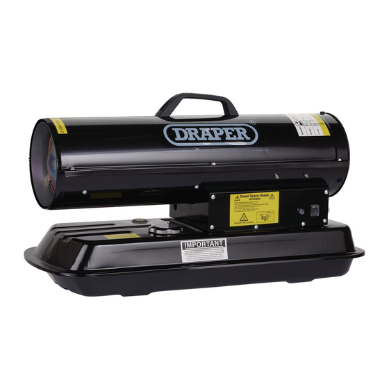
04174
These instructions accompanying the product are the original instructions. This document is part of the product, keep
it for the life of the product passing it on to any subsequent holder of the product. Read all these instructions before
assembling, operating or maintaining this product.
This manual has been compiled by Draper Tools describing the purpose for which the product has been designed,
and contains all the necessary information to ensure its correct and safe use. By following all the general safety
instructions contained in this manual, it will ensure both product and operator safety, together with longer life of the
product itself.
All photographs and drawings in this manual are supplied by Draper Tools to help illustrate the operation of
the product.
Whilst every effort has been made to ensure the accuracy of information contained in this manual, the Draper Tools
policy of continuous improvement determines the right to make modifications without prior warning.
Advertisement
Table of Contents

Related Manuals for Draper 04174


Summary of Contents for Draper 04174
- Page 1 All photographs and drawings in this manual are supplied by Draper Tools to help illustrate the operation of the product. Whilst every effort has been made to ensure the accuracy of information contained in this manual, the Draper Tools policy of continuous improvement determines the right to make modifications without prior warning.
-
Page 2: Title Page
Commercial copying, redistribution, hiring or lending is prohibited. No part of this publication may be stored in a retrieval system or transmitted in any other form or means without written permission from Draper Tools Limited. In all cases this copyright notice must remain intact. -
Page 3: Table Of Contents
CONTENTS 2.1 CONTENTS TITLE PAGE INTRODUCTION ......................2 REVISION HISTORY ....................2 UNDERSTANDING THIS MANUAL ................2 COPYRIGHT NOTICE ....................2 CONTENTS CONTENTS ......................... 3 GUARANTEE GUARANTEE ....................... 4 INTRODUCTION SCOPE ......................... 5 SPECIFICATION ......................5 HANDLING & STORAGE ..................... 5 HEALTH &... -
Page 4: Guarantee 3.1 Guarantee
This guarantee applies in lieu of any other guarantee expressed or implied and variations of its terms are not authorised. Your Draper guarantee is not effective unless you can produce upon request a dated receipt or invoice to verify your proof of purchase within the guarantee period. -
Page 5: Introduction
This product is suitable for the enthusiasts and tradespersons alike. Any application other than that it was intended for, is considered misuse. SPECIFICATION Stock no........04174 ......04175 ......04176 Part no..........DSH58 ......DSH68 ......DSH108 Motor: Rated voltage ....220-240V~ ...... 220-240V~ ..... 220-240V~ Rated frequency .... -
Page 6: Health & Safety Information
HEALTH AND SAFETY INFORMATION GENERAL HEATER SAFETY WARNINGS WARNING: Read all safety warnings and all instructions. Failure to follow the warnings and instructions may result in electric shock, fire and/or serious injury. Save all warnings and instructions for future reference. 1. - Page 7 HEALTH AND SAFETY INFORMATION safety measures reduce the risk of starting the heater accidentally. − Store idle heater out of the reach of children and do not allow persons unfamiliar with the heater or these instructions to operate the power tool. Heaters are dangerous in the hands of untrained users.
- Page 8 HEALTH AND SAFETY INFORMATION WARNING: Risk of Electric Shock! − Use only the electrical power (voltage and frequency) specified on the model plate of the heater. Use only a three-prong, grounded outlet and extension cord. − ALWAYS install the heater so that it is not directly exposed to water spray, rain, dripping water, or wind.
-
Page 9: Connection To The Power Supply
HEALTH AND SAFETY INFORMATION CONNECTION TO THE POWER SUPPLY CAUTION: Risk of electric shock. Do not open. This appliance is supplied with an approved plug and cable for your safety. The value of the fuse fitted is marked on the pin face of the plug. Should the fuse need replacing, ensure the substitute is of the correct rating, approved to BS1362 and ASTA or BS Kite marked. -
Page 10: Technical Description
TECHNICAL DESCRIPTION IDENTIFICATION (1) Upper shell. (10) 04174 (2) Hot air outlet. (3) Fuel gauge. (4) Fuel cap. (5) Lamp. (6) Fuel tank. (7) ON/OFF switch. (8) Pressure gauge. (9) Fan guard. (10) Handle. (1) Upper shell. 04175 (2) Hot air outlet. -
Page 11: Unpacking & Checking
Lay the contents out and check them against the parts list provided. If any part is damaged or missing; please contact the Draper Helpline (the telephone number appears on the Title page) and do not attempt to use the product. -
Page 12: Assembling The Heater
ASSEMBLING THE HEATER HANDLE (04174) – FIG.1 − Align the holes in the upper housing with the two holes in the handle. − Insert and tighten screws securely with screw driver. WHEEL AND HANDLE (04175 & 04176) – FIG.2 − Slide axle (6) through wheel support frame (8). -
Page 13: Operating The Heater
OPERATING THE HEATER STARTING HEATER – FIG.3 − Follow all ventilation and safety information. − Locate heater to provide maximum circulation of the heated air. Follow all location requirements noted in Safety Information on page 6. − Fill fuel tank with #1#2 diesel/fuel oil until fuel gauge points to “F”. -
Page 14: Storing & Transporting The Heater
10. STORING & TRANSPORTING THE HEATER 10.1 STORING & TRANSPORTING THE HEATER – FIG.4 If shipping, transport companies require fuel tanks to be empty. − Drain fuel tank. Note: Drain plug on underside of fuel tank. Remove drain plug to drain all fuel. −... -
Page 15: Maintenance
11. MAINTENANCE Use only original equipment replacement parts. The use of alternate or third party components can cause unsafe operating conditions, and will void your warranty. We suggest following a maintenance schedule as follows. WARNING: ENSURE HEATER HAS FULLY COOLED AND DISCONNECT FROM POWER SUPPLY BEFORE CONDUCTING ANY MAINTENANCE. -
Page 16: Spark Plug
11. MAINTENANCE 11.5 SPARK PLUG – FIG.9 − Clean and re-gap every 600 hours of operation, or replace as needed. After removing the Spark Plug (2), clean the terminals with a wire brush. Re-gap (1) the terminals to 3.5mm. 11.6 PHOTOCELL – FIGS.10–11 −... -
Page 17: Pump Rotor
− While heater is operating, turn relief valve clockwise to increase, counter-clockwise to decrease Use flat blade screwdriver to turn valve. Correct pump pressure is as follows: FIG. Stock number Pump Pressure (bar) 04174 0.33 04175 0.35 04176 0.37 Tolerance ± 10% −... -
Page 18: Wiring Diagram
11. MAINTENANCE 11.10 WIRING DIAGRAM – FIG.16 – 18 –... -
Page 19: Troubleshooting Guide
12. TROUBLESHOOTING 12.1 TROUBLESHOOTING GUIDE Problem Possible Cause Solution 1. Incorrect pump pressure. 1. Adjust Pump Pressure (page 17). 2. Dirty Input, Output or 2. Clean/replace Air Filter Lint Filter. (page 15). 3. Dirty Fuel Filter . 3. Clean/replace Fuel Filter (page 16). - Page 20 12. TROUBLESHOOTING 1. Broken electrical 1. Inspect all electrical connection between connections. See Wiring Main PCB and motor. Diagrams (page 18). 2. Temperature limit has 2.1 Push Power Switch to overheated. “OFF” and allow heater to cool for 10 minutes. Fan does not operate when Push Power Switch to heater is plugged in and...
-
Page 21: Disposal
13. DISPOSAL 13.1 DISPOSAL – At the end of the machine’s working life, or when it can no longer be repaired, ensure that it is disposed of according to national regulations. – Contact your local authority for details of collection schemes in your area. In all circumstances: •... - Page 22 – 22 –...
- Page 23 – 23 –...
- Page 24 ©Published by Draper Tools Limited. No part of this publication may be reproduced, stored in a retrieval system or transmitted in any form or by any means, electronic, mechanical photocopying, recording or otherwise without prior permission in writing from Draper Tools Ltd.
Need help?
Do you have a question about the 04174 and is the answer not in the manual?
Questions and answers