Advertisement
Quick Links
Advertisement

Related Manuals for Lutron Electronics Softswitch128


Summary of Contents for Lutron Electronics Softswitch128
- Page 1 Please Read Softswitch128 S w i t c h i n g S y s t e m Installation Guide...
-
Page 3: Table Of Contents
Remove Bypass Jumpers ............12 Overview Use this guide to successfully install a Softswitch128 system. This guide describes panel installation, control station wiring, and load activation. -
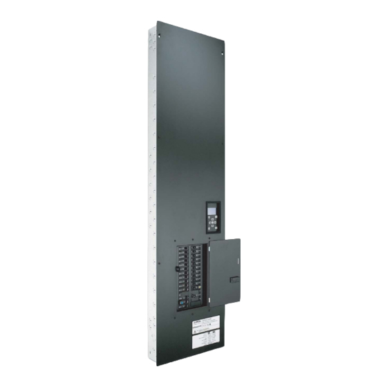
Page 4: Step 1: Panel Dimensions
(104) mounting bolt. This size is recommended. When flush mounting, mount the panel between flush and 1/8 in. (3 mm) below finished wall surface. The dimensions are shown in inches and (mm). Step by Step Installation Instructions for Softswitch128 System... - Page 5 This size is recommended. When flush mounting, mount the panel between flush and 1/8” (3 mm) below 4.15 (105) Bottom View finished wall surface. The dimensions are shown in inches and (mm). Step by Step Installation Instructions for Softswitch128 System...
-
Page 6: Step 2: Panel Mounting
Panel (if feed Panel (if feed through) through) Feed Wiring Feed Wiring Switch Switch Legs Legs Step by Step Installation Instructions for Softswitch128 Step by Step Installation Instructions for Softswitch128 Step by Step Installation Instructions for Softswitch128 System System System... -
Page 7: Step 3: Control Station Wiring
Control Station Wiring Control Station Wiring Overview The Softswitch128 system communicates to control stations using a Class 2/PELV low voltage link. Control stations include wallstations, contact closure input and output devices, and RS232 interfaces. Wallstations are to be mounted in a standard wallbox. Care must be taken in wiring the link; please follow these guidelines: •... - Page 8 Panel and Control Station Wiring Control Station Wiring Details: The control station link (Class 2/PELV) that connects all Softswitch128 devices (panels and control stations) must contain four wires: two for power and two for data. The illustration below shows wire sizes and wire type required.
-
Page 9: Step 4: Address Control Stations
Address Switches on that device. Use the space provided to record the name or location of the control. The order of the addresses on the link does not matter. This page will be helpful when programming the Softswitch128 system. See the Softswitch128 Setup and Maintenance Guide for programming details. -
Page 10: Step 5: Feed And Load Wiring
Step 5 Feed and Load Wiring Feed and Load Wiring Use the charts below to determine feed and load wiring sizes for Softswitch128 panels. Note that load circuit wiring sizes are shown bottom right. Panels with Branch Circuit Breakers Feed-Through Panels... -
Page 11: Step 6: Activate Loads In Bypass
AC RMS Current Meter Please Note: If onsite Factory Commissioning was purchased with the Softswitch128 System, you may want to stop here and complete the Control Location, Panel, and Control Station Tables that are located in the back of the Softswitch128 Setup and Maintenance Guide. -
Page 12: Step 7: Remove Bypass Jumpers
Output Terminals Switched Live Please Note: If Telephone Startup was purchased, please proceed to the Softswitch128 Setup and Maintenance Guide to continue the installation process. Please complete the required tables and charts that are called out on Start Up Notice and Check List in the Softswitch128 Setup and Maintenance Guide. - Page 16 5,633,540 and corresponding foreign patents. Fax: +813.5405.7496 Lutron, the sunburst logo, and GRAFIK Eye are registered trademarks; Softswitch128 is a trademark of Lutron Electronics Co., Inc. HONG KONG SALES OFFICE © 2004 Lutron Electronics Co., Inc. Lutron GL (Hong Kong) Tel: +852.2104.7733...
Need help?
Do you have a question about the Softswitch128 and is the answer not in the manual?
Questions and answers