Table of Contents
Advertisement
Please Read
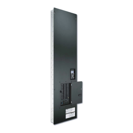
XPS48-1204ML-20 shown
Overview
Use this guide to successfully install a switching panel. This guide describes panel installation, wiring, and load
activation. For systems using rough-in panels, special instructions are included for keepout areas, panel
mounting, and installing the panel interior.
R
S w i t c h i n g P a n e l s
Installation Guide
Softswitch128
GRAFIK Systems
Contents
P P a a n n e e l l M M o o d d e e l l N N u u m m b b e e r r G G u u i i d d e e
P P a a n n e e l l D D i i m m e e n n s s i i o o n n s s
P P a a n n e e l l M M o o u u n n t t i i n n g g
W W i i r r i i n n g g
R R a a t t i i n n g g s s
R
(XPS) and
TM
(XP)
TM
2
3
4
5
6
7
8
9
10
10
11
12
13
14
15
16
16
17
17
19
20
Advertisement
Table of Contents

Subscribe to Our Youtube Channel
Related Manuals for Lutron Electronics Switch


Summary of Contents for Lutron Electronics Switch
-
Page 1: Table Of Contents
Dual-Voltage Panel: Feed and Load Wiring Panel with Branch Circuit Breakers: Feed and Load Wiring Panel with Isolation Switch: Feed and Load Wiring System Wiring Overview R R a a t t i i n n g g s s... -
Page 2: Softswitch128 (Xps)
Feed Type 4ML for 3 phase 4 wire main lugs 3ML for 1 phase 3 wire main lugs 4IS for 3 phase 4 wire isolation switch Branch Circuit Rating 20 for 20 A branch circuit breakers (120/277/347 V continuous load rating) -
Page 3: Grafik Systems (Xp)
Feed Type 4ML for 3 phase 4 wire main lugs 3ML for 1 phase 3 wire main lugs IS for 3 phase 4 wire isolation switch Branch Circuit Rating 20 for 20 A branch circuit breakers (120/277/347 V continuous load rating) -
Page 4: Panel Dimensions
Panel Dimensions Mini Panel Dimensions are in inches (mm). 21.50 (546) 24.00 24.50 (610) (622) Left Side 4 Installation Guide for Switching Panels 14.38 (365) Top View 15.875 (403) 8.00 (56) (203) 1.34 (34) 10.75 2.21 (273) (56) 15.13 (384) Front View Bottom View (107) -
Page 5: Standard Panel
Panel Dimensions (continued) Standard Panel Dimensions are in inches (mm). 41.75 (1060) 59.50 (1511) 59.00 (1499) Left Side 14.375 (365) Top View 15.875 (403) 2.43 8.00 (62) (203) 2.69 (68) Cover 2.43 11.00 (62) (279) 15.125 (394) Front View Bottom View 4.21 (107) 0.15... -
Page 6: Large Panel
Panel Dimensions (continued) Large Panel (120/277/347 V only) Dimensions are in inches (mm). 22.0 (559) Top View 6.30 23.50 (160) (597) 2.50 (64) 0.15 3.34 (85) 45.00 (1143) 63.00 63.50 (1613) (1600) Cover 18.50 (470) Right Side Left Side 22.75 (578) Front View 6.1 (155) Bottom View... -
Page 7: Extra-Large Panel
Panel Dimensions (continued) Extra-Large Panel (277/347 V Dimensions are in inches (mm). 3.45 (88) 82.0 82.50 (2083) (2096) Left Side only) 22.0 (559) Top View 23.50 (597) (76) 68.0 (1727) 18.5 (470) 22.75 (578) Front View 6.1 (155) Bottom View Installation Guide for Switching Panels (160) 0.15... -
Page 8: Panel And Tub Mounting
• Mount within 7º of true vertical. • Consult Dimensions page for dimensions, conduit knockouts, and mounting holes and hardware. • Install in accordance with all national and local electrical codes. Front View Feed wiring switch legs to loads PELV Distribution (Class 2: USA) panel wiring... -
Page 9: Rough-In Panel Interior Mounting
Panel Mounting (continued) Rough-In Panel Interior Mounting (Rough-in Panels ONLY) (120/277/347 V only) Mounting for SINT or XINT Plate: • Insert interior into TUB. • Rest interior on bottom of TUB. • Press interior flat into back of TUB. • Insert 3 screws (provided) as shown into interior to secure to TUB. •... -
Page 10: Feed-Through Panel: Feed And Load Wiring
Wiring Feed-Through Panel: Feed and Load Wiring • Use a trough when the switching panel is far away from the distribution panel. Splice neutrals in trough. • Wire the switching panel similar to a lighting distribution panel. Run feed and load wiring. •... -
Page 11: Panel With Branch Circuit Breakers: Feed And Load Wiring
• Run feed and load wiring. No other wiring or assembly required. The switching panel can provide temporary lighting: • Wire all loads. • Leave the bypass jumpers in place. • Use branch circuit breakers at the distribution panel to switch lights on and off. -
Page 12: Panel With Isolation Switch: Feed And Load Wiring
Wiring (continued) Panel with Isolation Switch: Feed and Load Wiring (230/220-240 V only) Bypass jumpers - Typical switch leg Switched Hot/Live #14-#10 AWG (2.5-4.0 mm Load Load Neutral #14-#10 AWG (2.5-4.0 mm Wire Sizes 230 V #14-#2 AWG (2.0-35 mm 220-240 V #14-#10 AWG (2.0-4.0 mm... -
Page 13: System Wiring Overview
System Wiring Overview Review the options below for information on wiring your panel correctly into your specific system. A. Softswitch128 (XPS) panel: Softswitch128 Setup and Operation Manual for detailed wiring information. B. GRAFIK Systems (XP) panel as a part of a GRAFIK Eye 4000 lighting system: GRAFIK Eye 4000 Installation, Setup, and Operation Manual and the system overview pictured here for detailed wiring information. -
Page 14: Softswitch128 (Xps)
230 V Panels with Branch Circuit Breakers Switch Feed Model Legs Type XPS8 3Ø 4W Isolation Switch XPS12 Accepts: XPS16 #14-#2 AWG XPS20 (2.0-35 mm XPS24 14 Installation Guide for Switching Panels Feed-Through (FT) and Rough-In (RI) Panels (120 V... -
Page 15: Grafik Systems (Xp)
XP42 220-240 V and 230 V Panels with Branch Circuit Breakers Switch Feed Model Legs Type XPS8 3Ø 4W Isolation Switch XPS12 Accepts: XPS16 XPS20 #14-#2 AWG (2.0-35 mm XPS24 Feed-Through (FT) and Rough-In (RI) Panels (120 V Model Model... -
Page 16: Temporary Lighting
16 A. D. Repeat step C for each circuit with completed load wiring. 16 Installation Guide for Switching Panels Input circuit breaker Bypass jumper protects the switch module from load faults. Load circuit wiring Hot/Live Switched hot/live AC RMS current meter... -
Page 17: Complete Installation
Complete Installation You have completed your panel installation. For Onsite Factory Commissioning, call Lutron Technical Support and select Startup to schedule a field service visit. Allow for 10 working days between day of call and scheduled visit. If you purchased Telephone Startup (Softswitch128/XPS only), stop here and complete the Control Location, Panel, and Control Station Tables that are located in the back of the Setup and Operation Manual. - Page 18 Notes 18 Installation Guide for Switching Panels...
-
Page 19: Warranty
National Electric Code (NEC) is a registered trademark of the National Fire Protection Association, Quincy, Massachusetts. Lutron and the sunburst logo are registered trademarks of Lutron Electronics Co., Inc.; Softswitch128 and GRAFIK Systems are trademarks of Lutron Electronics Co., Inc. © 2005 Lutron Electronics Co., Inc. -
Page 20: Contact Information
Technical support +44.(0)20.7680.4481 France Lutron LTC, S.A.R.L. 90 rue de Villiers, 92300 Levallois-Perret France TEL +33.(0)1.41.05.42.80 FAX +33.(0)1.41.05.01.80 FREEPHONE 0800.90.12.18 Germany Lutron Electronics GmbH, Landsberger Allee 201, 13055 Berlin, Germany TEL +49.(0)30.9710.4590 FAX +49.(0)30.9710.4591 FREEPHONE 00800.5887.6635 Italy Lutron LDV, S.r.l. FREEPHONE 800.979.208 Spain, Barcelona Lutron CC, S.R.L.
Need help?
Do you have a question about the Switch and is the answer not in the manual?
Questions and answers