Table of Contents
Advertisement
Quick Links
Advertisement
Table of Contents

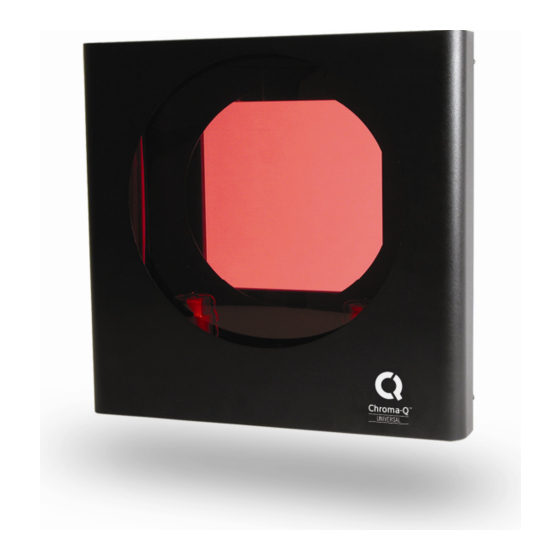
Summary of Contents for Chroma Universal
- Page 1 Chroma-Q™ Universal User Manual Version 1.4 September 2012 PN: 111-0501...
- Page 2 (c) by operation outside the specifications contained in the user documentation; (d) by the use of spare parts not manufactured or sold by Chroma-Q or by the connection or integration of other equipment or software not approved by Chroma-Q unless the Customer provides acceptable proof to Chroma-Q that the defect or damage was not caused by the above;...
- Page 3 Chroma-Q products are safe, effective, and fully satisfactory for the intended end use. Suggestions of use shall not be taken as inducements to infringe any patent. Chroma-Q sole warranty is that the product will meet the sales specifications in effect at the time of shipment.
-
Page 4: Table Of Contents
…………………………………………………………. 12 Troubleshooting ……………………………………………….…………. 13 Technical overview ……………………………………………….…………. 14 Technical specifications ……………………………………………….…………. 14 Drawings ……………...…………………………………………………….………... 15 Outside dimensions of the unit ……………………………………………….…………. 15 Gel dimensions ……………………………………………….…………. 16 Examples of mounting bracket positions ……………………………………….…………. 17 www.chroma-q.com Universal User Manual V1.4 September 2012... -
Page 5: Product Overview
Control and power cables The Chroma-Q Universal utilises an XLR 4-pin cable system. This is used for power & data transfer. Pins 2 & 3 are for ANSI E1.11 USITT DMX 512-A data. Pins 1 & 4 are for 24VDC power. -
Page 6: Operating The Unit
& all units receive power if one link of the chain is faulty. Operating the unit All the unit functions are accessed using the LED display & the three push-button switches on the rear panel. www.chroma-q.com Universal User Manual V1.4 September 2012... -
Page 7: Modes Of Operation (Inc. Dmx Addressing)
If the red button is held down & the brown button pressed, the unit will reset to the factory default settings. This feature is particularly useful when the units are used in many different configurations or shows. The reset function is also available via DMX (see remote operation section of this manual). www.chroma-q.com Universal User Manual V1.4 September 2012... - Page 8 However the display will re-activate when any button is pressed. Press the brown or black buttons once to switch between On (1) & Off (0) (the default is On). Press red to save the new setting. www.chroma-q.com Universal User Manual V1.4 September 2012...
- Page 9 The Factory default settings put the unit in its safest operating mode. Fan speed = 4 (fast) Gel saver = 0 (off) Gel speed = 1 (slow) Display = 1 (on) Remote operation = 1 (normal) Display flip = standard www.chroma-q.com Universal User Manual V1.4 September 2012...
- Page 10 ‘disP P P P lay’ mode Switches on/off the display Switches the display on or off. Display will re-activate when any button is pressed. Press brown or black to switch between on (1) & off (0). www.chroma-q.com Universal User Manual V1.4 September 2012...
-
Page 11: Gel Loading
Press red to save the new settings Gel loading Changing the gel string on the Chroma-Q Universal is not difficult, but it may take some time & practice to accomplish, if the user is not familiar with the unit. There are two methods of loading gel strings on the Chroma-Q Universal, manually or using the power assisted loading method (EZ Load). - Page 12 Press the brown push button to move the gel string back onto the TUR. Use the push buttons to move the gel to & fro, checking that the gel is sitting correctly on the TUR's. Allow the unit to self-calibrate by pressing the brown & black buttons simultaneously or by cycling power to the unit. www.chroma-q.com Universal User Manual V1.4 September 2012...
-
Page 13: Mounting The Unit
Note: See drawing section of this manual. The Chroma-Q Universal is designed for mounting in an upright position with the base of the unit below the fixture. Do not mount in an inverted position with the base of the unit above the fixture, as the rising heat from the fixture may cause the gel string damage. -
Page 14: Troubleshooting
Various PAR 64 Outside Strand 2K Note: The Chroma-Q Universal should always be used with the safety wire provided. Troubleshooting The first vertical bar indicates that there is power (24VDC). The second vertical bar indicates that there is data (DMX). -
Page 15: Technical Overview
2-24 gels Cooling: 2 fan design Cooling Speed: Multiple speeds DMX protocol: ANSI E1.11 USITT DMX 512-A DMX addressing: Digitally via 3 push buttons and LED display Working Voltage: 24 VDC (+/- 10%) www.chroma-q.com Universal User Manual V1.4 September 2012... -
Page 16: Drawings
Note: To simplify the choice of power supply we use the "PU" (Power Unit) to calculate the load requirements of the Chroma- Q system. For example a PS-08 will supply up to 8 PU's, so you can plug-in 5 Chroma-Q Universals (5 x 1.5PU = 7.5PU) into a PS-08. -
Page 17: Gel Dimensions
Gel dimensions www.chroma-q.com Universal User Manual V1.4 September 2012... -
Page 18: Examples Of Mounting Bracket Positions
Examples of mounting bracket positions www.chroma-q.com Universal User Manual V1.4 September 2012...


