Table of Contents
Advertisement
Quick Links
Advertisement
Table of Contents

Subscribe to Our Youtube Channel
Related Manuals for Chroma Inspire CHINHLRGBW32E


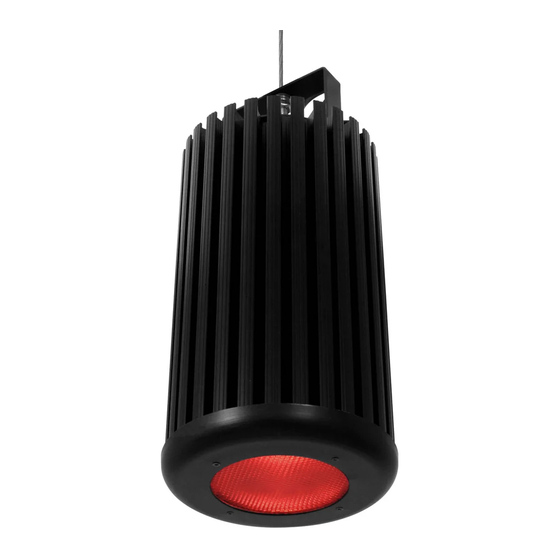
Summary of Contents for Chroma Inspire CHINHLRGBW32E
- Page 1 ® Chroma-Q Inspire™ Terminal Strip User Manual Part Number: CHINHLRGBW32E, CHINHLRGBW42E, CHINHLRGBW65E, CHINHLW32E, CHINHLW42E, CHINHLW65E (Model: 632-1500, 632-1600, 632-1700, 632-2500, 632-2600, 632-2700) Software Version (Engine) 2.2 Manual: 632-0706, V1.6 Jul. 2019...
- Page 2 (c) by operation outside the specifications contained in the user documentation; (d) by the use of spare parts not manufactured or sold by Chroma-Q or by the connection or integration of other equipment or software not approved by Chroma-Q unless the Customer provides acceptable proof to Chroma-Q that the defect or damage was not caused by the above;...
- Page 3 Chroma-Q products are safe, effective, and fully satisfactory for the intended end use. Suggestions of use shall not be taken as inducements to infringe any patent.
- Page 4 If you experience difficulties with any Chroma-Q products please contact your local dealer. If your local dealer is unable to help then please contact support@chroma-q.com. If you are having trouble finding what you are looking for on our website, then contact our Chroma-Q marketing department by sending an email to marketing@chroma-q.com. www.chroma-q.com Inspire User Manual V1.6 Jul 2019...
- Page 5 If the specified cables are not long enough for an intended cable run, consult Chroma-Q for assistance in finding or creating a safe alternative solution. • Provide a means of locking out AC mains power that allows power to the installation to be shut down and made impossible to reapply, even accidentally, during work on the installation.
-
Page 6: Table Of Contents
Optics ..........................13 Control ..........................13 Thermal Performance ...................... 13 Updating the LED engine software .................. 14 Troubleshooting ........................15 Specification .......................... 16 Technical Specifications ....................16 Drawings – Dimensions ....................17 Maintenance ........................... 17 www.chroma-q.com Inspire User Manual V1.6 Jul 2019... -
Page 7: Product Overview
Chroma-Q Color Force™ range. The Inspire provides a choice of beautiful whites, soft pastels and bold saturates - all from one fixture. By incorporating industry standard DMX-512 control to the external control box, the Inspire is able to integrate seamlessly with an existing DMX infrastructure and can be controlled by any DMX supported lighting console. -
Page 8: Operation
If the cable length between the subsequent fixtures on the link is less than 100 feet (30 meters) no additional terminator is needed. If longer, a 120 Ω resistor can be added at the fixture data input where the longer cable connects. www.chroma-q.com Inspire User Manual V1.6 Jul 2019... - Page 9 Figure 1: System Diagram Maximum DMX cable length from Data Out 1/2/3 to 1 fixture must not exceed 500’/152m. www.chroma-q.com Inspire User Manual V1.6 Jul 2019...
- Page 10 120 Ω resistor. Terminal blocks with resistors installed are included in the External Control Box. See Inspire Terminal Strip Data Cable Termination on the next section. Figure 2 Bottom view of the fixture www.chroma-q.com Inspire User Manual V1.6 Jul 2019...
- Page 11 Figure 3: AC Power Cable Wiring www.chroma-q.com Inspire User Manual V1.6 Jul 2019...
- Page 12 Terminal blocks with resistors installed are included in the External Control Box. Note: In order to eliminate line noise, be sure to terminate the data common wire. Figure 4 Input Data Cable Wiring www.chroma-q.com Inspire User Manual V1.6 Jul 2019...
- Page 13 To avoid short connections, keep some gap between the wire terminations to the connector. Once inserted, tighten the screws, then gently pull and make sure the connection is tight. www.chroma-q.com Inspire User Manual V1.6 Jul 2019...
-
Page 14: Mounting
A provision for a fixing hold is built into the fixture. Other mounting options, such as a yoke, or recessing mounting kits are available. Consult your local representative or the Chroma-Q website for more details. Optional Mounting Kits and Accessories... -
Page 15: Thermal Performance
10. The Uploader display shows “DONE” upon completion of the upload. 11. Power-cycle the fixture. 12. Repeat step 6 to step 10 if the uploading process is interrupted (power and/or data). (For more detail, see the Quick Start Guide of the Chroma-Q Uploader) Cable Adaptor: XLR5 to Terminal Block www.chroma-q.com... -
Page 16: Troubleshooting
Internal temperature of the Check area ventilation. fixture is over the limit. • • Flicker No termination resistor Check the first fixture in each run if it has the 120 Ω terminating resistor. www.chroma-q.com Inspire User Manual V1.6 Jul 2019... -
Page 17: Specification
W @ 65° (approx.) Beam Distribution Symmetrical direct illumination Adjustable 1,000 – 10,000K Colour Gamut Performance enhanced Lamp Life L70 at 50,000 hours **For exact measurements please refer to the line drawings below www.chroma-q.com Inspire User Manual V1.6 Jul 2019... -
Page 18: Drawings - Dimensions
Do not spray liquids on the front or rear panel. If the front enclosure requires cleaning, wipe with a mild detergent on a damp cloth. www.chroma-q.com Inspire User Manual V1.6 Jul 2019...
Need help?
Do you have a question about the Inspire CHINHLRGBW32E and is the answer not in the manual?
Questions and answers