
Related Manuals for LELY COSMIX S


Summary of Contents for LELY COSMIX S
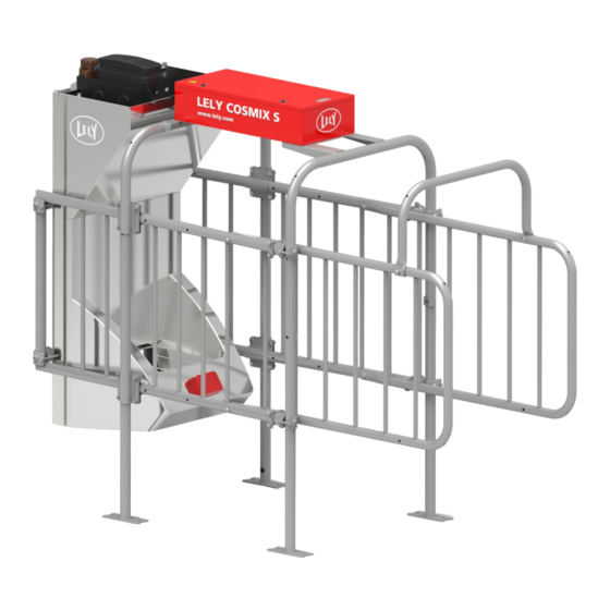
- Page 1 LELY COSMIX S Concentrate Feeder Installation and Operator Manual 5.2309.8509.0 A EN – English Original...
- Page 2 INTENTIONALLY BLANK...
- Page 3 Viseo, Voyager, Walkway and Welger are registered trademarks of the Lely Group. The right of exclusive use belongs to the companies of the Lely Group. All rights reserved. The information given in this publication is provided for information purposes only and does not constitute an offer for sale.
- Page 4 INTENTIONALLY BLANK TRADEMARKS, COPYRIGHT AND DISCLAIMER...
- Page 5 LIST OF INCLUDED AMENDMENTS Issue Date (yy/mm) Chapter(s) Remarks 15/07 • Long distance (LD) tag functionality added: machine 5.2309.0040.x • Installation of the rear fences changed Adjustment of the photocell (H/HR models) added • • Feed presence sensor removed • Pressure reducer added to control unit Several other minor updates •...
- Page 6 INTENTIONALLY BLANK LIST OF INCLUDED AMENDMENTS...
- Page 7 Operator Technical Training Manual is not covered by the warranty scheme. Warranty does not apply to consequential damage which does not involve the machine itself. All systems are tested. However in the event of a malfunction Lely cannot be held responsible for consequential damage. WARRANTY RESTRICTIONS...
- Page 8 INTENTIONALLY BLANK WARRANTY RESTRICTIONS...
- Page 9 COSMIX S Concentrate Feeder. Study and understand this information thoroughly before configuration of the COSMIX S. Failure to do so could result in damage to equipment. Please consult your local Lely service provider if you do not understand the information in this manual, or if you need additional information.
- Page 10 COSMIX S. At the end of each visit, all work done on the COSMIX S must be written in the logbook and the logbook must be signed by the certified technician.
- Page 11 Technician Training All the technicians certified by Lely Industries have completed an approved training program, and passed written and practical examinations during and at the end of the training program. The training is given by a product specialist. The examinations are done under supervision of a master product specialist and include troubleshooting and corrective maintenance of the COSMIX S.
- Page 12 INTENTIONALLY BLANK PREFACE...
-
Page 13: Table Of Contents
4.5.3 Interaction between the COSMIX S Components ........4-21 INSTALLATION ..................5-1... - Page 14 ..............5-3 Install the COSMIX S .
- Page 15 10.1 Overview COSMIX S with One or Two Feed Hoppers ........10-1...
- Page 16 INTENTIONALLY BLANK viii Table of Contents...
-
Page 17: Introduction
The information in this manual is for farmers and technicians. • Farmers use the information to test and adjust the COSMIX S or to list overviews • Technicians use the information to install and setup the COSMIX S. - Page 18 INTENTIONALLY BLANK INTRODUCTION...
-
Page 19: Safety
Introduction The safety alert symbol identifies important safety messages on your COSMIX S Concentrate Feeder and in the manual. When you see this symbol, be alert to the possibility of personal injury or death. Follow the instruction of the safety message. -
Page 20: Safety Instructions
2.3.1 General Safety Read and understand the manual and all safety signs before you • connect power supplies to operate, maintain or adjust the COSMIX S Concentrate Feeder • Only trained persons are permitted to operate the COSMIX S Concentrate Feeder •... -
Page 21: Electrical Safety
COSMIX S Concentrate Feeder • Make sure the electrical grounding of the electrical system and all parts of the COSMIX S Concentrate Feeder meet the local rules and regulations Replace any damaged electrical lines, conduits, switches and •... -
Page 22: Safety Decals
Concentrate Feeder • Disconnect and isolate the electrical power supply, release pneumatic pressure before you do work on the COSMIX S Concentrate Feeder • Take extreme care when you work near or with high-pressure pneumatic systems. If possible, depressurize the system before you do work on it •... - Page 23 Figure 3. Position of the safety decal SAFETY...
- Page 24 INTENTIONALLY BLANK SAFETY...
-
Page 25: Specifications
• Electrical power • 100 - 240 VAC Earthing Earthing of the COSMIX S must comply with current earthing • regulations for barns (obey local rules and standards) • The earth wire must be connected to the earth point •... - Page 26 Warranty on electronics will not be given if the earthing is not correctly installed. T4C network Network connection: • LAN CAT.5e Network cable, S-FTP 200 MHz (foil-screened twisted pair with overall screening (copper braiding)) with steel RJ-45 connector Maximum cable length: 100 m (109 yd) (use a switch if the distance is •...
-
Page 27: Description And Operation
The COSMIX S is installed in the barn. The COSMIX S is connected to the T4C network. The COSMIX S gets input from and sends output to the T4C Farm Management software. The following figures show the main components of the COSMIX S with Qwes ACT, Qwes H/HR and Qwes leg identification. - Page 28 Figure 4. Main components COSMIX S with Qwes ACT identification KEY: 1. Feed hopper - 2. Control box - 3. Rear portal - 4. Restraining bracket - 5. Rear fences - 6. ID-reader - 7. Front portal - 8. Feed bin - 9. Side fence...
- Page 29 Figure 5. Main components COSMIX S with Qwes H/HR identification KEY: 1. Feed hopper - 2. Control box - 3. Rear portal - 4. Restraining bracket - 5. Rear fences - 6. Front portal - 7. Feed bin - 8. Side...
- Page 30 Figure 6. Main components COSMIX S with Qwes H/HR-LD identification KEY: 1. Feed hopper - 2. IR reader (External IDU 530) - 3. Control box - 4. Rear portal - 5. Restraining bracket - 6. Rear fences - 7. Front portal - 8. Feed bin - 9. Side fence...
-
Page 31: Component Description
Figure 7. Main components COSMIX S with Qwes leg identification KEY: 1. Feed hopper - 2. Control box - 3. Rear portal - 4. Side fence - 5. Restraining bracket - 6. Rear fences - 7. EWA transformer - 8. Floor antenna mat - 9. Front portal - 10. Feed bin - 11. Side fence Component Description 4.2.1... -
Page 32: Feed Unit
All parts are installed on a plate. 4.2.2.1 Feed Hoppers The COSMIX S has up to four feed hoppers. Each feed hopper has a feed dosing unit that provides portions of concentrates. In most cases the feed hoppers are filled by tube feeders that are connected to silos. - Page 33 Power supply with safe life switch • • Network switch (optional). • Air pressure reducer 4.2.3.1 ADS 3830 pcb The ADS 3830 pcb (see figure 8 on page 4-8) controls the valves that supply air to the cylinders of the feed dosing unit. The pcb is installed in the control unit.
- Page 34 (infrared LED) and a receiving element (photodiode). It is installed on a bracket on the base plate of the control unit. The photoelectric sensor gets input when a cow is in the COSMIX S. The photoelectric sensor sends output to the ADS 3830 pcb.
- Page 35 Figure 9. Control unit (Qwes ACT) KEY: 1. Pressure reducer - 2. ADS 3830 pcb - 3. Network switch (optional) - 4. Power supply (ADS 3830 pcb) - 5. Safe life switch (optional) - 6. Air valve - 7. E-Link connection - 8. Air valve block DESCRIPTION AND OPERATION...
- Page 36 Figure 10. Control unit (Qwes H/HR) KEY: 1. Pressure reducer - 2. ADS 3830 pcb - 3. Network switch (optional) - 4. Infrared ID reader - 5. Photoelectric sensor - 6. Power supply (ADS 3830 pcb) - 7. Safe life switch (optional) - 8. Air valve - 9. E-Link connection - 10. Air valve block 4-10 DESCRIPTION AND OPERATION...
- Page 37 Figure 11. Control unit (Qwes H/HR-LD) KEY: 1. Pressure reducer - 2. ADS 3830 pcb - 3. Network switch (optional) - 4. Photoelectric sensor - 5. Power supply (ADS 3830 pcb) - 6. Safe life switch (optional) - 7. Air valve - 8. E-Link connection - 9. Air valve block DESCRIPTION AND OPERATION 4-11...
-
Page 38: Cow Identification (Id) Readers
Figure 12. Control unit (Qwes leg) KEY: 1. Pressure reducer - 2. ADS 3830 pcb - 3. Velos box - 4. Network switch (optional) - 5. Power supply (ADS 3830 pcb) - 6. Safe life switch (optional) - 7. Air valve - 8. E-Link connection - 9. Air valve block 4.2.4 Cow Identification (ID) Readers 4.2.4.1 Qwes ACT Cow ID Reader... -
Page 39: Operator Interface
The Velos box (VP1001) (3)(see figure 12 on page 4- 12) installed in the Qwes ISO leg control box on top of the COSMIX S. On the side of the control box are cable glands. The CAN-bus cable of the Velos box is connected to connector J608 on the ADS2412 PCB. -
Page 40: Service Interfaces
The E-Link Manual Controller controls and monitors the COSMIX S. The E-link Manual Controller has an LCD display and nine buttons that enable the user to give commands and change values in the COSMIX S. The LCD display also shows reports and alarms. -
Page 41: Menu Structure E-Link
The E-Link has the following buttons: • Soft buttons (1): confirm the action on the LCD display above the applicable button Start/Stop button (2): starts or stops an action • • Enter button (4): open the selected function or the next menu screen •... - Page 42 Figure 15. The E-Link menu structure 4.4.2.1 Version info 'Version info' displays information about the software installed on the ADS 3830 pcb. The menu displays the following items: Software version • • Time when the software was compiled • Date when the software was compiled Version info of the ID-reader.
- Page 43 The menu item 'Keep blocker open' is only applicable for service engineers. In the IR version of the COSMIX S a photocell is installed to support the ID-detector. The setting Photocell active is used to switch ON the photocell (value 0 is OFF, value 1 is ON).
- Page 44 Menu item 'Dev addr CRS+' sets the identification number of the CRS+. The default setting is 151. Menu item 'IP Address' sets the IP address of the COSMIX S, as used in the T4C network. Menu item 'ETH address' displays the ethernet (MAC) address of the ADS 3830 pcb.This address is fixed and can not be changed.
- Page 45 The menu item 'Tag id' displays the tag ID when a cow is present in the COSMIX S and the value 1 if the cow is detected by the (optional) photocell (see page 8-6).
-
Page 46: 4.4.3.1 Cosmix Service Interface
T4C (see page 4-13). If you install the COSMIX S or a new ADS 3830 pcb, the data on that board should be replaced by the data in T4C. The menu 'Calibrate Valves' is used to adjust the supplied feed doses to the indicated amount (see page 8-4). -
Page 47: Feeding
Interaction between the COSMIX S Components The COSMIX S is connected to the T4C network. After installation, the COSMIX S is given a device ID and an IP address. These settings are used in the T4C software. The T4C software In the T4C software the feeding criteria are set. - Page 48 INTENTIONALLY BLANK 4-22 DESCRIPTION AND OPERATION...
-
Page 49: Installation
Preparation 5.2.1 List of Supplied Parts The COSMIX S package must contain the parts listed below. Make sure all these items are present before you start the installation. If items are missing, contact your local Lely service provider. The COSMIX S is supplied with either one, two, three or four feed hoppers. - Page 50 Install the earth wire and get it approved by the energy company • • Install an external feed delivery system Consult the local Lely service provider for the correct position of the • COSMIX S in the barn. • Read and understand the COSMIX S Installation and Operator Manual.
-
Page 51: Preparation By Lely
The correct position of the COSMIX S will depend on the operational management of the farm. Analyze the operational requirements of the farm before you install the COSMIX S. This will make sure the COSMIX S is installed in the correct position. -
Page 52: Install The Cosmix S
Figure 16. Example: installation in the barn KEY: 1. Spare room - 2. Cosmix concentrate feeder - 3. Walk alley - 4. Barn Install the COSMIX S Wear safety shoes. 5.3.1 Preparation This procedure requires a minimum of two persons. -
Page 53: Install The Side Fences On The Portals
5.3.2 Install the Side Fences on the Portals Parts 2× Side fence • • 1× Front portal • 1× Rear portal • 4× Bracket set (1.5 in×1.5 in) • 16× Bolt, washer, nut 4× T-clamps. • Installation This procedure requires a minimum of two persons. Put the front portal (1) (see figure 17 on page 5-6) on the floor, hold it. - Page 54 Loosely install the side fences with the T-clamps on the rear portal with the four bolts (2). Figure 17. Install the portals and fences KEY: 1. Front portal - 2. Allen bolt - 3. Bolt - 4. T-clamps - 5. Brackets - 6. Side fences INSTALLATION...
-
Page 55: Level, Square And Tighten The Fences
Figure 18. Lift the fences and install the rear portal KEY: 1. Rear portal - 2. Bolt - 3. Allen bolt - 4. Allen bolt - 5. Screw driver 5.3.3 Level, square and tighten the Fences Special tools • Level Installation Make sure the distance between the front and rear portal is 101.5 cm (40.0 in), move the front portal (1) if necessary. - Page 56 Make sure the distances between the front sides of both side fences and the opposite brackets (1) (see figure 20 on page 5-9) are equal (A = B). Tighten the bolts and nuts on the four brackets (1) on the front portal.
-
Page 57: Install The Portals On The Floor
Figure 20. Square the angles KEY: 1. Front portal A: Distance between front side of side fence and opposite bracket B: Distance between front side of side fence and opposite bracket 5.3.4 Install the Portals on the Floor Parts 8× Expander bolt M12×120×80 •... -
Page 58: Install The Control Unit
5.3.5 Install the Control Unit 5.3.5.1 Install the Control Unit - General For installation of a COSMIX S with Qwes H/HR-LD identification refer to Install the Control Unit - Qwes H/HR-LD Identification (see page 5-20) Parts 1× Control unit •... - Page 59 Figure 21. Install the control unit KEY: 1. CE-plate - 2. Control unit - 3. Carriage bolt - 4. Cable shoe - 5. Washer - 6. Cap nut 5.3.5.2 Install the Control Unit - Qwes H/HR-LD Identification Parts • 1× Control unit 4×...
-
Page 60: Install The Front Plate
Install the cable shoe (4) from the earthing cable on the carriage bolt. Install the reader-bracket assembly (8)(see figure 22 on page 5-12) and the control unit (6) on the brackets (3 and 7) on the portals with four carriage bolts (4), washers (2) and cap nuts (1). Close the cover of the control unit (6). - Page 61 2× Mounting pipe • • 4× T-clamp This procedure requires a minimum of two persons. Installation Loosely install the four T-Clamps (8)(see figure 24 on page 5-14) on the two mounting pipes (1) with an 8 mm Allen key. Install the four bolts (9) and eight nuts (7) on the mounting pipes. The mounting pipes can be installed on three different heights on the back plate (3) and (4) Install the two mounting pipes on the rear plate with the four nuts...
- Page 62 Figure 24. Install the pipes on the front plate KEY: 1. Mounting pipe - 2. Front plate - 3. Lower mounting pipe installation holes - 4. Upper mounting pipe installation holes - 5. Nut - 6. Washer - 7. Nuts - 8. T-clamp - 9. Bolt 5-14 INSTALLATION...
-
Page 63: Install The Feed Bin And The Feed Hopper On The Front Plate
Figure 25. Install the front plate on the fences KEY: 1. T-clamp - 2. Allen bolt - 3. Bolt 5.3.7 Install the Feed Bin and the Feed Hopper on the Front Plate Parts • Dosing units (1-4) Feed bin • •... - Page 64 Install the feed hopper cover (3) on the front plate with the clamping spring (4). Figure 26. Install the feed bin KEY: 1. Bolt - 2. Washer - 3. Nut - 4. Feed bin 5-16 INSTALLATION...
-
Page 65: Install The Rear Fences
Figure 27. Install the dosing unit, feed hopper and feed funnel KEY: 1. Dosing unit - 2. Feed funnel cover - 3. Feed hopper cover - 4. Clamping spring 5.3.8 Install the Rear Fences Parts • 2× Rear fence • 4×... - Page 66 Support the rear fence and loosely install the lower side of the rear fence on the side fence with a 70 mm bolt (3) a washer (2) and a cap nut (1). Loosely install the U-bolt (4) with the clamp (5), the nuts (6) and the cap nuts (7) to the lower side of the fence.
-
Page 67: Install The Restraining Bracket
Figure 29. Install the rear fences KEY: 1. Cap nut - 2. Washer - 3. Bolt (70 mm) - 4. U-bolt - 5. Clamp - 6. Nut - 7. Cap nut 5.3.9 Install the Restraining Bracket Parts 1× Restraining bracket •... -
Page 68: Install A Qwes Leg Id Reader And A Floor Antenna
KEY: 1. Cap nut - 2. Bolt - 3. Restraining bracket 5.3.10 Install a Qwes leg ID Reader and a Floor Antenna This section only applies when you have a COSMIX S with Qwes leg identification. Parts • 1× Floor antenna mat 1×... - Page 69 Feed the coax cable through the hole in the upper side of the frame (3) to the hole in the front frame (2). Connect the EWA transformer Remove the cover (2) (see figure 32 on page 5-23)from the EWA transformer box. Loosen four bolts that attach the pcb on the EWA transformer box.
- Page 70 Figure 31. Install the antenna mat KEY: 1. Floor antenna mat - 2. Hole (front frame) - 3. Hole (upper side frame) 5-22 INSTALLATION...
- Page 71 Figure 32. Connect the Qwes leg-ID reader cable to the EWA transformer KEY: 1. Coax cable through gland nut - 2. Cover - 3. Potentiometer - 4. Wire - 5. Terminal strip INSTALLATION 5-23...
- Page 72 Figure 33. Connect a Qwes leg ID reader KEY: 1. Jumper wire connector - 2. Jumper wire connector - 3. Antenna wire connector - 4. Antenna wire connector - 5. Trimmer coil - 6. Shielding connector - 7. Inner wire connector 5-24 INSTALLATION...
-
Page 73: Connect The Cosmix S
1. EWA transformer box - 2. Upper cover EWA transformer housing - 3. Lower cover EWA transformer housing - 4. Nut - 5. Washer - 6. Cable shoe - 7. Washer Connect the COSMIX S Use a cable channel to protect the cables and tubes against external mechanical effects. -
Page 74: Connect The Id-Reader Cable
Connect the blue air tube to the tube connectors (10) on the valve unit. Feed the compressed air supply tube into the control unit. Connect the air supply tube to the air coupling of the pressure reducer (1)(see figure 9 on page 4-9). Figure 35. -
Page 75: Install The Earthing
Install the cable connector on the pcb with the bolt. Install the cable with the clamp and the two bolts on the pcb. Make sure the clamp and the shielding are connected. Qwes leg ID reader Insulate the wire shielding with a piece of heat shrink. Connect the wire shielding to the - antenna connector (5) on the Velos box (bottom-right). -
Page 76: Install A Type 1 Network Connector
5.4.4.2 Connector types Figure 36. Network Connector Types KEY: 1. a) Type 1 network connector (T-568A) - 1. b) Type 1 network connector (T-568B) - 2. Type 2 network connector (T-568A) 5.4.5 Install a Type 1 Network Connector Special tools •... - Page 77 Splice the wires (6) and (7). Sort the wires by color according to one of the tables. A Type 1 Network Connector can be configured accordingly a Type A or Type B wiring scheme. Use the same scheme (A or B) on both cable ends.
-
Page 78: Install A Type 2 Network Connector
Figure 37. Install a type 1 network connector 5.4.6 Install a Type 2 Network Connector Special tools 5-30 INSTALLATION... - Page 79 Ethernet crimping tool • Preparation Make sure the network cable is of type S-FTP 200MHz CAT5e. Cut a piece of network cable to the correct length. Feed the network cable into the control unit. Installation Install the connector cover and the cap on the network cable (1) (see figure 38 on page 5-33).
- Page 80 Push both plates until you hear a click (7). Push the connector cover on the connector until you hear a click (8). Install the cap on the cover (8). 5-32 INSTALLATION...
- Page 81 Figure 38. Install a type 2 network connector INSTALLATION 5-33...
-
Page 82: Install The Network Cable On An Earthing Clamp
5.4.7 Install the Network Cable on an Earthing Clamp Installation Remove one of the earthing clamps (8)(see figure 35 on page 5-26). Connect the network connector to the ADS 3830 pcb (3). Mark the position of the earthing clamp on the network cable. Remove the network connector from the ADS 3830 pcb. -
Page 83: Remove Or Install The Covers From The Feed Unit
1. Clamping spring - 2. Feed hopper cover - 3. Feed funnel cover Setup the COSMIX S Make sure the E-Link is connected and the main switch is switched Set the IP-address. The IP-address for the first COSMIX S is 10:4:1:11 for the second 10:4:1:12 and so on. INSTALLATION 5-35... - Page 84 Set the device address of the COSMIX S Set the Device Address of the Cosmix (see page 8-2). The device address for the first COSMIX S is 11, for the second 12 and so on. Set the device address T4C (see page 8-2).
-
Page 85: Operating Instructions
Go to the page Analysis/Reports > Reports Select the report 'Feeding - Rest Feed'. Make sure feed types in the COSMIX S have a unique name. This makes it possible to report feeding details from the COSMIX S apart from the milking robot. -
Page 86: List A Device Intake Overview
List a Device Intake Overview The report ''Feeding - Device Intake Overview' displays the total feed intake per device (milking robot and COSMIX S) and per feed type in a given period. Go to the page Analysis/Reports > Reports Select the report 'Feeding - Device Intake Overview'. -
Page 87: Maintenance
MAINTENANCE There is no maintenance information in this manual. MAINTENANCE... - Page 88 INTENTIONALLY BLANK MAINTENANCE...
-
Page 89: Test And Adjustment
• Adjustments with the service interface (see page 8-14). Connect or Remove the E-Link Manual Controller Block the cow traffic to the COSMIX S before you do this procedure. Connect Loosen the cap until you can remove it from the connector on the control unit (7)(see figure 9 on page 4-9). -
Page 90: Set The Device Address Of The Cosmix
After a few seconds you return to the main menu. 8.3.2 Set the Device Address of the Cosmix Block the cow traffic to the COSMIX S before you do this procedure. Use the E-Link manual controller for this procedure. In the main menu, select 'Network settings' and push button [ Select 'Dev addr Cosmix' and push button [ Use soft buttons [<] or [>] to select the position you want to... -
Page 91: Make Basic Software Settings
Make Basic Software Settings 8.4.1 Display the Software Version Block the cow traffic to the COSMIX S before you do this procedure. Use the E-Link manual controller for this procedure. In the main menu, select 'Version info' and push button [ Push button [ After a few seconds you return to the main menu. -
Page 92: Make The Photocell Active
After a few seconds you return to the menu 'Settings'. 8.4.4 Make the Photocell Active Block the cow traffic to the COSMIX S before you do this procedure. Only applicable for Qwes - H/HR readers. Use the E-Link manual controller for this procedure. -
Page 93: Set The Portion Size
Set the correct portion size (see page 8-5). 8.4.6 Set the Portion Size Block the cow traffic to the COSMIX S before you do this procedure. Use the E-Link manual controller for this procedure. In the main menu, select ‘Settings’ and push [... -
Page 94: Test The Operation Of The Cosmix S
Test the Operation of the COSMIX S 8.5.1 Test the Time Setting Block the cow traffic to the COSMIX S before you do this procedure. Use the E-Link manual controller for this procedure. In the main menu, select 'Testing' and push button [ Select 'Time' and push button [ Make sure the values are correct. -
Page 95: Test The Dosing Units
1 if the cow is detected by the (optional) photocell. Push button [ 8.5.4 Test the Dosing Units Block the cow traffic to the COSMIX S before you do this procedure. Use the E-Link manual controller for this procedure. Make sure the feed funnels are not empty. - Page 96 Open the EWA transformer box (see page 5-23). Find the trimmer coil (2) on the EWA transformer pcb (1). Adjust Turn the trimmer coil on the EWA transformer pcb clockwise until it is completely in the coil housing with a non-metal screwdriver. Turn the trimmer anti-clockwise until the green LED (4) lights up.
- Page 97 Figure 41. Adjust the EWA transformer KEY: 1. EWA transformer pcb - 2. Trimmer coil - 3. Velos box - 4. Indication LEDs - 5. Terminal strip TEST AND ADJUSTMENT...
-
Page 98: Adjust The Photoelectric Sensor
Figure 42. Remove/Install the Qwes leg ID reader KEY: 1. Cap nut - 2. Washer - 3. Bolt A: Open the EWA transformer housing B: Close the EWA transformer housing C: Attach the EWA transformer housing to the front portal D: Install the EWA transformer housing with M8 bolts, washers and nuts. - Page 99 Adjust To set the cow detection area (see figure 43 on page 8-11): Turn the detection distance adjuster (4)(see figure 44 on page 8-12) completely counterclockwise with the screwdriver to the minimum detection distance (I)(see figure 45 on page 8-13). Put a matt black object at approximately 120 cm (47.2 in) above the ground.
- Page 100 Figure 44. Photocell LEDs and detection distance adjuster KEY: 1. Detection LED (red) - 2. Adjuster indicator - 3. Stability LED (green) - 4. Detection distance adjuster 8-12 TEST AND ADJUSTMENT...
-
Page 101: Adjustments In The T4C Software
Select the number of feed types. Select the feed type by each number. • • Select 'Robot Feed' to prevent a cow being fed on the COSMIX S when the cow is near to be milked. Click on the button [Save]. 8.8.2 Add a Feed Type Use T4C for this procedure. -
Page 102: Set The Feed Speed
Fill out the form. Click on the button [Save]. Create feed types for all feed types presented in the COSMIX S, even when they are the same as on the Astronaut A3 milking robot. This way, automatic feed tables can control the distribution between the milking robot and the COSMIX S. - Page 103 Select field 'CalibrateTagsActive'. Select ON. Select 'Cal. Tag1'. Activate the dosing unit with a cow tag. Make sure the dosing unit supplies 10 portions of concentrate. Use a balance to measure the weight of the feed. TEST AND ADJUSTMENT 8-15...
- Page 104 INTENTIONALLY BLANK 8-16 TEST AND ADJUSTMENT...
-
Page 105: Troubleshooting
Read the responder number from the cow responder. Make sure the number is less than 32000. 9.2.3 Clean the Dosing Unit Danger of being entangled by rotating parts.Keep hands, loose clothing, and long hair away from moving parts during operation of the COSMIX S. TROUBLESHOOTING... - Page 106 Find the defective dosing unit. Open the control box (2)(see figure 6 on page 4-4). Remove the compressed air supply tube (1)(see figure 35 on page 5-26) from the air valves block. Remove the feed hopper cover (see page 5-35). Remove the feed funnel cover.
-
Page 107: Diagrams
DIAGRAMS 10.1 Overview COSMIX S with One or Two Feed Hoppers DIAGRAMS 10-1... - Page 108 INTENTIONALLY BLANK 10-2 DIAGRAMS...
-
Page 109: Glossary Of Terms
PC: Personal Computer Approx: Approximately PCB: printed circuit board with electrical components. Astronaut: Lely Astronaut A3 or A4 milking robot portion size: size of one portion of concentrates CAN: controller area network (also CAN-bus), network standard for communication between psi: pounds per square inch... - Page 110 INTENTIONALLY BLANK Glossary of Terms...
Need help?
Do you have a question about the COSMIX S and is the answer not in the manual?
Questions and answers