
Subscribe to Our Youtube Channel
Related Manuals for Yamaha XRS900 Series


Summary of Contents for Yamaha XRS900 Series
- Page 1 Read this manual carefully before operating this vehicle. OWNER’S MANUAL MTM850 BAE-28199-E1...
- Page 2 For Europe Declaration of Conformity: Hereby, YAMAHA MOTOR ELECTRONICS Co., Ltd declares that the radio equipment type, IMMOBILIZER, BAE-00 is in compliance with Directive 2014/53/EU. The full text of the EU declaration of conformity is available at the following internet address: https://global.yamaha-motor.com/eu_doc/...
- Page 3 Welcome to the Yamaha world of motorcycling! As the owner of the MTM850, you are benefiting from Yamaha’s vast experience and newest technology regarding the de- sign and manufacture of high-quality products, which have earned Yamaha a reputation for dependability.
- Page 4 Important manual information EAU10134 Particularly important information is distinguished in this manual by the following notations: This is the safety alert symbol. It is used to alert you to potential personal injury hazards. Obey all safety messages that follow this symbol to avoid possible injury or death.
- Page 5 Important manual information EAU10201 MTM850 OWNER’S MANUAL ©2020 by Yamaha Motor Co., Ltd. 1st edition, August 2019 All rights reserved. Any reprinting or unauthorized use without the written permission of Yamaha Motor Co., Ltd. is expressly prohibited. Printed in Japan.
-
Page 6: Table Of Contents
Table of contents Safety information ......1-1 Auxiliary DC connector....3-26 Checking the engine idling Sidestand ........3-26 speed........6-15 Description ........2-1 Ignition circuit cut-off system..3-27 Checking the throttle grip free Left view ......... 2-1 play........... 6-15 For your safety – pre-operation Right view ........ - Page 7 Table of contents Checking the front fork ....6-27 Checking the steering....6-28 Checking the wheel bearings ..6-28 Battery .......... 6-29 Replacing the fuses ...... 6-30 Replacing the headlight bulb ..6-33 Replacing the auxiliary light bulb .......... 6-34 Brake/tail light .......
-
Page 8: Safety Information
Safety information EAU1028C Take a training course. Beginners • Use extra caution when you are should receive training from a cer- approaching passing tified instructor. Contact an autho- through intersections, since in- Be a Responsible Owner rized motorcycle dealer to find out tersections are the most likely As the vehicle’s owner, you are respon- about the training courses nearest... - Page 9 Safety information tice riding your motorcycle with both hands and keep both control levers, footrests, or wheels where there is no traffic until you feet on the passenger footrests. and cause injury or an accident. have become thoroughly famil- Never carry a passenger unless Always wear protective clothing iar with the motorcycle and all of...
- Page 10 Yamaha accessories, which are avail- to minimize imbalance or instabili- of the motorcycle is changed. To avoid able only from a Yamaha dealer, have the possibility of an accident, use ex- been designed, tested, and approved ...
- Page 11 Yamaha, even if sold and limit suspension travel, steering not recommended. installed by a Yamaha dealer.
- Page 12 Safety information Check that the fuel cock (if equipped) is in the off position and that there are no fuel leaks. Shift the transmission into gear (for models with a manual transmis- sion). Secure motorcycle with tie-downs or suitable straps that are attached to solid parts of the motorcycle, such as the frame or upper front fork triple clamp (and...
-
Page 13: Description
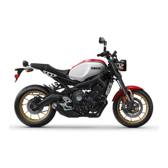
Description EAU10411 Left view 1. Spring preload adjuster (page 3-22) 2. Rebound damping force adjuster (page 3-24) 3. Seat (page 3-21) 4. Storage compartment (page 3-22) 5. Spring preload adjuster (page 3-24) 6. Shift pedal (page 3-14) 7. Engine oil drain bolt (page 6-10) -
Page 14: Right View
Description EAU10421 Right view 3, 4 1. Fuses (page 6-30) 9. Brake pedal (page 3-15) 2. Fuel tank cap (page 3-18) 10.Rear brake fluid reservoir (page 6-21) 3. Spring preload adjuster (page 3-22) 4. Rebound damping force adjuster (page 3-22) 5. -
Page 15: Controls And Instruments
Description EAU10431 Controls and instruments 1. Clutch lever (page 3-14) 2. Left handlebar switches (page 3-12) 3. Main switch/steering lock (page 3-2) 4. Multi-function meter unit (page 3-5) 5. Front brake fluid reservoir (page 6-21) 6. Right handlebar switches (page 3-12) 7. -
Page 16: Instrument And Control Functions
Do not place near magnets. ing standard keys to a Yamaha dealer Do not place near items that to have them re-registered. transmit electrical signals. -
Page 17: Main Switch/Steering Lock
Instrument and control functions EAU10474 on. The engine can be started. The key To lock the steering Main switch/steering lock cannot be removed. To prevent battery discharge, do not leave the key in the on position without the engine running. ... -
Page 18: Indicator Lights And Warning Lights
If this EAU11032 lights for an extended length of time Turn signal indicator lights “ ” and occurs, have a Yamaha dealer check may cause the battery to discharge. “ ” the vehicle. Each indicator light will flash when its... - Page 19 EAU73172 Use extra caution to avoid pos- Engine trouble warning light “ ” page 6-10), have a Yamaha dealer sible wheel lock during emer- This warning light comes on if a prob- check the vehicle. gency braking. lem is detected in the engine or other Have a Yamaha dealer check the ...
-
Page 20: Multi-Function Meter Unit
Yamaha dealer to have the standard keys re-registered. When the vehicle is turned on, the light 1. - Page 21 Instrument and control functions Tachometer a traction control system display a multi-function display The “QS” icon does not function. The multi-function meter unit can be switched between kilometers and miles. Set the multi-function display to the odometer mode or a tripmeter mode, and then press the bottom set button until the dis- 1.
- Page 22 Travel at a constant speed. ments, frame, and “ ” will flash repeat- Select the transmission gear that edly. Have a Yamaha dealer check the is appropriate for the vehicle vehicle. speed. 1. Drive mode display...
- Page 23 Instrument and control functions Multi-function display This display indicates which drive The tripmeters “TRIP” show the dis- mode has been selected: “STD”, “A” or tance traveled since they were last re- “B”. For more details on the modes and set. on how to select them, see pages 3-12 To reset a tripmeter, select it by push- and 3-14.
- Page 24 Instrument and control functions _ C Clock _ _ :_ _ ODO Instantaneous fuel consumption changes. When using miles: If traveling at speeds under 20 km/h (12 mi/h), “_ _._” is displayed. ODO TRIP 1 TRIP 2 (TRIP F) ...
- Page 25 Instrument and control functions Coolant temperature Air temperature amount of fuel necessary to travel 100 km. “AVE_ _._ MPG”: The average distance that can be traveled on 1.0 Imp.gal of fuel. To switch the average fuel consump- tion display settings, push the bottom set button until the display changes.
- Page 26 Instrument and control functions Clock 6. Push the top set button to set the To adjust the brightness minutes. 1. Turn the main switch off. 7. Push the bottom set button to con- 2. Push and hold the bottom set but- firm settings and start the clock.
-
Page 27: D-Mode (Drive Mode)
Instrument and control functions EAU47636 smooth and sporty drivability from the EAU1234M D-mode (drive mode) Handlebar switches low-speed range to the high-speed D-mode is an electronically controlled range. Left engine performance system with three mode selections: “STD”, “A”, and “B”. Mode “A”... - Page 28 Instrument and control functions Right EAU12461 of the traction control system and Turn signal switch “ ” the TCS settings. To signal a right-hand turn, push this switch to “ ”. To signal a left-hand EAU54212 turn, push this switch to “ ”.
-
Page 29: Clutch Lever
Instrument and control functions gine not running, otherwise the bat- EAU12823 EAU12876 Clutch lever Shift pedal tery may discharge. EAU73321 Drive mode switch “MODE” EWA18440 WARNING Do not change the drive mode while the vehicle is moving. With the throttle grip closed, press this switch to change the drive mode (page 3-12) in the following order: 1. -
Page 30: Brake Lever
EAU63040 Brake lever Brake pedal The brake lever is located on the right The Yamaha ABS (Anti-lock Brake side of the handlebar. To apply the front System) features a dual electronic con- brake, pull the lever toward the throttle trol system, which acts on the front and grip. -
Page 31: Traction Control System
However, special tools are turns, when accelerating hard at a required, so please consult your sharp lean angle, or while braking, Yamaha dealer. and cannot prevent front wheel slip- ping. As with any vehicle, approach ECA20100 NOTICE surfaces that may be slippery with 1. - Page 32 Yamaha dealer TCS “1” minimizes traction control sys- accurately. check the vehicle as soon as possible. tem assist. 4. Have a Yamaha dealer check the TCS “2” Resetting the traction control sys- vehicle and turn off the “ ” warn- TCS “2”...
-
Page 33: Fuel Tank Cap
Instrument and control functions EAU13077 the key cannot be removed if the cap is EAU13222 Fuel tank cap Fuel not properly closed and locked. Make sure there is sufficient gasoline in EWA11092 the tank. WARNING EWA10882 Make sure that the fuel tank cap is WARNING properly closed after filling fuel. - Page 34 If gaso- line spills on your clothing, change your clothes. EAU86072 Your Yamaha engine was designed to use unleaded gasoline with a research 1. Fuel tank filler tube octane number of 95 or higher. If en- 2.
-
Page 35: Fuel Tank Overflow Hose
Instrument and control functions or vehicle performance problems. EAU80200 Fuel tank overflow hose ECA11401 See page 6-10 for canister information. NOTICE Use only unleaded gasoline. The use of leaded gasoline will cause severe damage to internal engine parts, such as the valves and piston rings, as well as to the exhaust system. -
Page 36: Catalytic Converter
Instrument and control functions EAU13435 EAU57992 Catalytic converter Seat The exhaust system contains catalytic To remove the seat converter(s) to reduce harmful exhaust emissions. 1. Open the seat lock cover, insert EWA10863 the key into the seat lock, and then WARNING turn the key counterclockwise. -
Page 37: Storage Compartment
Instrument and control functions hicle. EAU14454 EAU62453 Storage compartment Adjusting the front fork EWA14671 WARNING Always adjust the spring preload on both fork legs equally, otherwise poor handling and loss of stability may result. Each front fork leg is equipped with a spring preload adjusting bolt. - Page 38 Instrument and control functions Spring preload setting: Minimum (soft): Distance A = 19.0 mm (0.75 in) Standard: Distance A = 16.0 mm (0.63 in) Maximum (hard): Distance A = 4.0 mm (0.16 in) Rebound damping force The rebound damping force is adjusted on the right fork leg only.
-
Page 39: Adjusting The Shock Absorber Assembly
Instrument and control functions suspension. EAU57944 Adjusting the shock absorber 3 2 1 7 6 5 4 assembly This shock absorber assembly is equipped with a spring preload adjust- ing ring and a rebound damping force adjusting screw. ECA10102 NOTICE To avoid damaging the mechanism, do not attempt to turn beyond the 1. -
Page 40: Luggage Strap Holders
Maximum (hard): worn-out shock absorber as- 0 turn(s) in direction (b) sembly yourself. Take the shock absorber assembly to a Yamaha dealer for any service. When turning the damping force adjust- er in direction (b), it may turn beyond 3-25... -
Page 41: Auxiliary Dc Connector
Instrument and control functions Yamaha dealer repair it if it does not EAU70641 EAU15306 Auxiliary DC connector Sidestand function properly. This vehicle is equipped with an auxilia- The sidestand is located on the left side ry DC connector. Consult your Yamaha of the frame. -
Page 42: Ignition Circuit Cut-Off System
Instrument and control functions EAU44895 Ignition circuit cut-off system This system prevents in-gear engine starts unless the clutch lever is pulled and the sidestand is up. Also, it will stop the running engine should the sides- tand be lowered while the transmission is in gear. - Page 43 The neutral switch may not be working. 6. Move the sidestand up. The motorcycle should not be ridden until 7. Pull the clutch lever. checked by a Yamaha dealer. 8. Shift transmission into gear. 9. Move the sidestand down. Does the engine stall? The sidestand switch may not be working.
-
Page 44: For Your Safety - Pre-Operation Checks
• If necessary, add recommended coolant to specified level. 6-13 • Check cooling system for leakage. • Check operation. • If soft or spongy, have Yamaha dealer bleed hydraulic system. • Check brake pads for wear. Front brake • Replace if necessary. - Page 45 • Make sure that operation is smooth. • Check throttle grip free play. Throttle grip 6-15, 6-25 • If necessary, have Yamaha dealer adjust throttle grip free play and lubricate cable and grip housing. • Make sure that operation is smooth. Control cables 6-25 •...
- Page 46 For your safety – pre-operation checks ITEM CHECKS PAGE Instruments, lights, signals • Check operation. — and switches • Correct if necessary. • Check operation of ignition circuit cut-off system. Sidestand switch 3-26 • If system is not working correctly, have Yamaha dealer check vehicle.
-
Page 47: Operation And Important Riding Points
The vehicle can now be operated nor- there is a control or function you do not between 0 and 1600 km (1000 mi). For mally. understand, ask your Yamaha dealer. this reason, you should read the follow- ECA10311 NOTICE EWA10272 ing material carefully. -
Page 48: Starting The Engine
Operation and important riding points not work as described above, have a EAU86590 EAUM3632 Starting the engine Yamaha dealer check the vehicle. The ignition circuit cut-off system will 3. Shift the transmission into the neu- enable starting when: This model is equipped with: tral position. -
Page 49: Shifting
Operation and important riding points EAU16674 ECA10261 EAU16811 Shifting Tips for reducing fuel NOTICE consumption Even with the transmission in the neutral position, do not Fuel consumption depends largely on coast for long periods of time your riding style. Consider the following with the engine off, and do not tips to reduce fuel consumption: tow the motorcycle for long dis-... -
Page 50: Parking
Operation and important riding points EAU17214 Parking When parking, stop the engine, and then remove the key from the main switch. EWA10312 WARNING Since the engine and exhaust system can become very hot, park in a place where pedestri- ans or children are not likely to touch them and be burned. -
Page 51: Periodic Maintenance And Adjustment
– possibly leading to any repair establishment or individual pending on the weather, terrain, geo- death. See page 1-2 for more in- that is certified (if applicable). Yamaha graphical location, and individual use, dealers are trained and equipped to formation about carbon monox- the maintenance intervals may need to perform these particular services. -
Page 52: Tool Kit
However, a torque wrench and other tools are necessary to perform certain maintenance work correctly. If you do not have the tools or experi- ence required for a particular job, have your Yamaha dealer perform it for you. -
Page 53: Periodic Maintenance Charts
EAU71033 Periodic maintenance charts Items marked with an asterisk should be performed by your Yamaha dealer because these items require special tools, data, and technical skills. From 50000 km (30000 mi), repeat the maintenance intervals starting from 10000 km (6000 mi). - Page 54 Periodic maintenance and adjustment ODOMETER READING ANNUAL ITEM CHECK OR MAINTENANCE JOB 1000 km 10000 km 20000 km 30000 km 40000 km CHECK (600 mi) (6000 mi) (12000 mi) (18000 mi) (24000 mi) • Check the air cut-off valve, reed Air induction valve, and hose for damage.
-
Page 55: General Maintenance And Lubrication Chart
(24000 mi) • Perform dynamic inspection using Diagnostic system Yamaha diagnostic tool. check • Check the error codes. 2 * Air filter element • Replace. Every 40000 km (24000 mi) • Check operation. Clutch ... - Page 56 Periodic maintenance and adjustment ODOMETER READING ANNUAL ITEM CHECK OR MAINTENANCE JOB 1000 km 10000 km 20000 km 30000 km 40000 km CHECK (600 mi) (6000 mi) (12000 mi) (18000 mi) (24000 mi) • Check chain slack, alignment and condition. Every 1000 km (600 mi) and after washing the motorcycle, riding in the rain or Drive chain •...
- Page 57 Periodic maintenance and adjustment ODOMETER READING ANNUAL ITEM CHECK OR MAINTENANCE JOB 1000 km 10000 km 20000 km 30000 km 40000 km CHECK (600 mi) (6000 mi) (12000 mi) (18000 mi) (24000 mi) Rear suspension relay arm and 23 * ...
- Page 58 Periodic maintenance and adjustment EAU72800 Air filter • This model’s air filter is equipped with a disposable oil-coated paper element, which must not be cleaned with com- pressed air to avoid damaging it. • The air filter element needs to be replaced more frequently when riding in unusually wet or dusty areas. ...
-
Page 59: Checking The Spark Plugs
Instead, have Clean the surface of the spark plug while pulling it out; to install it, twist a Yamaha dealer check the vehicle. gasket and its mating surface, and then it back and forth while pushing it in. -
Page 60: Canister
Periodic maintenance and adjustment To check the engine oil level EAU36112 EAU1990G Canister Engine oil 1. After warming up the engine, wait The engine oil level should be checked a few minutes for the oil level to regularly. In addition, the oil must be settle for an accurate reading. - Page 61 Skip steps 4–6 if the oil filter cartridge is An oil filter wrench is available at a 1. Engine oil filler cap not being replaced. Yamaha dealer. 2. O-ring 4. Remove the oil filter cartridge with 5. Apply a thin coat of clean engine 6.
- Page 62 Periodic maintenance and adjustment 11. Stop the engine, wait a few min- Tightening torque: utes for the oil level to settle, and Oil filter cartridge: then check the oil level one last 17 N·m (1.7 kgf·m, 13 lb·ft) time. NOTICE: Do not operate 7.
-
Page 63: Why Yamalube
3. Minimum level mark standards. Thus, Yamalube mineral, 3. If the coolant is at or below the If genuine Yamaha coolant is not avail- semisynthetic and synthetic oils have minimum level mark, remove the able, use an ethylene glycol antifreeze their own distinct characters and value. -
Page 64: Air Filter Element
EAU33032 Changing the coolant maintenance and lubrication chart. The coolant must be changed at the in- Have a Yamaha dealer replace the air tervals specified in the periodic mainte- filter element. nance and lubrication chart. Have a Yamaha dealer change the coolant. -
Page 65: Checking The Engine Idling Speed
This service must be performed when 1. Throttle grip free play the engine is cold. Throttle grip free play: 3.0–5.0 mm (0.12–0.20 in) Periodically check the throttle grip free play and, if necessary, have a Yamaha dealer adjust it. 6-15... -
Page 66: Tires
Operation of this vehicle with im- combined weight of the rider, passen- cracked, have a Yamaha dealer re- ger, cargo, and any accessories. proper tire pressure may cause se- place the tire immediately. - Page 67 EWA10472 WARNING characteristics of the motorcy- cle may be different, which Have a Yamaha dealer replace could lead to an accident. excessively worn tires. Besides Always make sure that the valve being illegal, operating the vehi- ...
-
Page 68: Cast Wheels
Other tires may run for cracks, bends, warpage or oth- the danger of bursting at super er damage before each ride. If any damage is found, have a Yamaha high speeds. dealer replace the wheel. Do not Brand-new tires can have a rela- ... -
Page 69: Checking The Brake Lever Free Play
If the specified free play cannot be ob- play tained as described above or if the clutch does not operate correctly, have a Yamaha dealer check the internal clutch mechanism. 1. No brake lever free play There should be no free play at the brake lever end. -
Page 70: Brake Light Switches
Periodic maintenance and adjustment EAU36505 EAU22393 touches the brake disc, have a Yamaha Brake light switches Checking the front and rear dealer replace the brake pads as a set. brake pads The brake light should come on just be- fore braking takes effect. The brake... -
Page 71: Checking The Brake Fluid Level
If the brake Use only the specified brake flu- fluid level goes down suddenly, have a id; otherwise, the rubber seals Yamaha dealer check the cause before 6-21... -
Page 72: Changing The Brake Fluid
EAU22734 EAU22762 Changing the brake fluid Drive chain slack Have a Yamaha dealer change the The drive chain slack should be brake fluid every 2 years. In addition, checked before each ride and adjusted have the seals of the master cylinders if necessary. - Page 73 Periodic maintenance and adjustment EAU57971 To adjust the drive chain slack Consult a Yamaha dealer before ad- justing the drive chain slack. 1. Loosen the axle nut and the lock- nut on each side of the swingarm. 1. Drive chain slack 1.
-
Page 74: Cleaning And Lubricating The Drive Chain
Periodic maintenance and adjustment may contain substances that EAU23026 Cleaning and lubricating the could damage the O-rings. [ECA11112] drive chain The drive chain must be cleaned and lubricated at the intervals specified in the periodic maintenance and lubrica- tion chart, otherwise it will quickly wear out, especially when riding in dusty or wet areas. -
Page 75: Checking And Lubricating The Cables
Yamaha dealer at the intervals speci- bricated if necessary. ed if necessary. If a cable is damaged fied in the periodic maintenance chart. -
Page 76: Brake And Clutch Levers
Periodic maintenance and adjustment Shift pedal Clutch lever EAU23144 Checking and lubricating the brake and clutch levers The operation of the brake and clutch levers should be checked before each ride, and the lever pivots should be lu- bricated if necessary. Brake lever Recommended lubricant: Recommended lubricants:... -
Page 77: Checking And Lubricating The Sidestand
WARNING! To avoid injury, be checked before each ride, and the ed by a Yamaha dealer at the intervals securely support the vehicle so sidestand pivot and metal-to-metal specified in the periodic maintenance... -
Page 78: Checking The Steering
[EWA10752] have a Yamaha dealer check or re- the periodic maintenance and lubrica- 2. Hold the lower ends of the front pair it. tion chart. If there is play in the wheel... -
Page 79: Battery
To charge the battery necessary. Electrolyte is poisonous and Have a Yamaha dealer charge the bat- 3. Fully charge the battery before in- dangerous since it contains sul- stallation. NOTICE: When install- tery as soon as possible if it seems to... -
Page 80: Replacing The Fuses
Periodic maintenance and adjustment the main switch off, then con- EAU73340 Replacing the fuses nect the positive lead before connecting negative Fuse box 1 is located behind the right lead. side panel. [ECA16842] To access fuse box 1, remove and in- 4. - Page 81 Periodic maintenance and adjustment 1. Ignition fuse 1. Main fuse 1. Radiator fan motor fuse 2. ABS control unit fuse 2. Fuse box 2 2. Backup fuse 3. Parking lighting fuse 3. Fuel injection system fuse 3. Electronic throttle valve fuse 4.
- Page 82 2.0 A possibly a fire. [EWA15132] 3. Turn the key to “ON” and turn on the electrical circuit in question to check if the device operates. 4. If the fuse immediately blows again, have a Yamaha dealer 6-32...
-
Page 83: Replacing The Headlight Bulb
Periodic maintenance and adjustment EAU34387 Replacing the headlight bulb This model is equipped with a halogen bulb headlight. If the headlight bulb burns out, replace it as follows. ECA26690 NOTICE Do not touch the glass part of the headlight bulb. Otherwise the luminosity and the life of the bulb may be adversely affected. -
Page 84: Replacing The Auxiliary Light Bulb
6. Install the headlight unit by install- place it as follows. ing the bolts. 1. Remove the headlight unit. (See 7. Have a Yamaha dealer adjust the page 6-33.) headlight beam if necessary. 2. Remove the auxiliary light bulb socket (together with the bulb) by pulling it out. -
Page 85: Brake/Tail Light
1. Remove the turn signal light lens If the brake/tail light does not come on, by removing the screw. have a Yamaha dealer check it. 1. Turn signal light bulb 3. Insert a new bulb into the socket, push it in, and then turn it clock- wise until it stops. -
Page 86: License Plate Light
1. Maintenance stand (example) self. However, should your motorcycle require any repair, take it to a Yamaha Since this model is not equipped with a dealer, whose skilled technicians have centerstand, use maintenance stands... - Page 87 Periodic maintenance and adjustment heaters or furnaces. Gasoline or gasoline vapors can ignite or ex- plode, causing severe injury or property damage. 6-37...
-
Page 88: Troubleshooting Chart
Remove the spark plug and check the electrodes. The engine does not start. Have a Yamaha dealer check the vehicle. Check the compression. 4. Compression The engine does not start. There is compression. - Page 89 Start the engine. If the engine overheats again, have a The coolant level Yamaha dealer check and repair the cooling system. is OK. If coolant is not available, tap water can be temporarily used instead, provided that it is changed to the recommended coolant as soon as possible.
-
Page 90: Motorcycle Care And Storage
Be performance and extend the useful life high-pressure washers sure to consult a Yamaha dealer for of many components. Washing, clean- steam-jet cleaners. Excessive advice on what products to use be- ing, and polishing will also give you a water pressure may cause water fore cleaning the vehicle. - Page 91 Motorcycle care and storage gasoline, rust removers, brake to do the job. Avoid spraying water 4. Rinse off thoroughly with clean wa- fluid, or antifreeze, etc. directly into the muffler, instrument ter. Be sure to remove all deter- panel, air inlet, or other inner areas gent residues, as they can be such as underseat storage com- harmful to plastic parts.
-
Page 92: Storage
Motorcycle care and storage operating the vehicle. EWA20660 EAU83472 [EWA20650] Storage WARNING 5. Treat rubber, vinyl, and unpainted Always store the vehicle in a cool, dry Contaminants left on the brakes or plastic parts with a suitable care place. If necessary, protect it against tires can cause loss of control. - Page 93 Motorcycle care and storage perform any outstanding mainte- into the spark plug bore. the tires from becoming degraded nance. c. Install the spark plug cap onto in one spot. 2. Follow all instructions in the Care the spark plug, and then place 9.
-
Page 94: Specifications
Specifications Dimensions: Fuel injection: EAU84805 Starting system: Electric starter Overall length: Throttle body: Engine oil: 2075 mm (81.7 in) ID mark: Overall width: Recommended brand: B901 00 Drivetrain: 815 mm (32.1 in) Overall height: Gear ratio: 1140 mm (44.9 in) 1st: Seat height: 2.667 (40/15) - Page 95 Specifications Loading: Front turn signal light: 10.0 W Maximum load: Rear turn signal light: 170 kg (375 lb) 10.0 W (Total weight of rider, passenger, cargo and Auxiliary light: accessories) Front brake: 5.0 W License plate light: Type: 5.0 W Hydraulic dual disc brake Rear brake: Type:...
-
Page 96: Consumer Information
These identification numbers are needed when registering the vehicle with the authorities in your area and when ordering spare parts from a Yamaha dealer. VEHICLE IDENTIFICATION NUM- 1. Vehicle identification number 1. Engine serial number... -
Page 97: Diagnostic Connector
Yamaha dealer. Vehicle data uploaded will be handled appropriately according to the following Privacy Policy. Privacy Policy https://www.yamaha-motor.eu/eu/ privacy/privacy-policy.aspx Yamaha will not disclose this data to a third party except in the following cas-... - Page 98 Consumer information es. In addition, Yamaha may provide vehicle data to a contractor in order to outsource services related to the han- dling of vehicle data. Even in this case, Yamaha will require the contractor to properly handle the vehicle data we provided and Yamaha will appropriate- ly manage the data.
-
Page 99: Index
Index Drive chain slack ........6-22 Maintenance and lubrication, periodic ..6-5 Maintenance, emission control system ... 6-3 ABS ............3-15 Matte color, caution ........ 7-1 ABS warning light ........3-4 Engine break-in ........5-1 Model label ..........9-2 Air filter element........6-14 Engine idling speed, checking....6-15 Multi-function meter unit ...... - Page 100 Index Tires ............6-16 Tool kit ............ 6-2 Traction control system......3-16 Traction control system indicator light..3-4 Traction control system switch....3-13 Troubleshooting ........6-36 Troubleshooting chart ......6-38 Turn signal indicator lights ...... 3-3 Turn signal light bulb, replacing .... 6-35 Turn signal switch .........
- Page 102 Original instructions PRINTED IN JAPAN 2019.08-0.2×1 !
Need help?
Do you have a question about the XRS900 Series and is the answer not in the manual?
Questions and answers