Table of Contents
Advertisement
Advertisement
Table of Contents
Troubleshooting

Subscribe to Our Youtube Channel
Related Manuals for Yamaha Venture XVZ13TFS


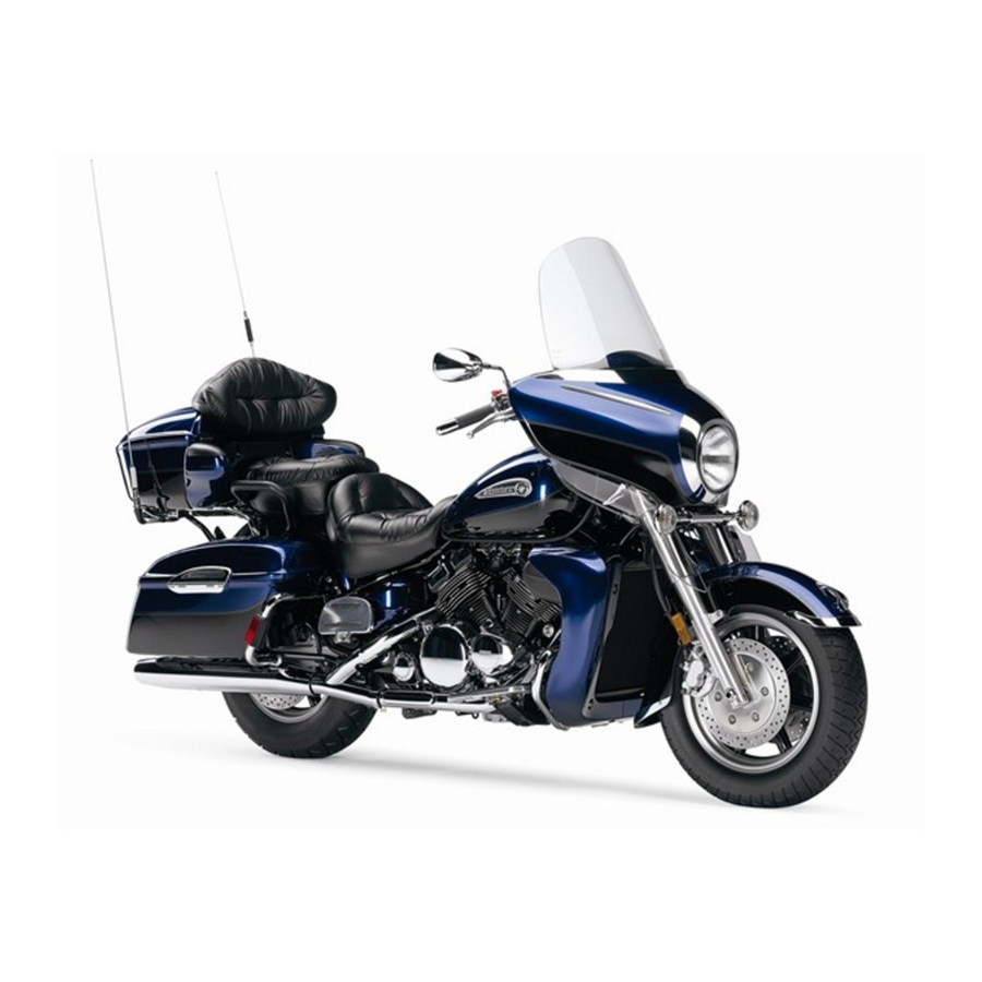
Summary of Contents for Yamaha Venture XVZ13TFS
- Page 1 OWNER’S MANUAL XVZ13TFS(C) XVZ13TFMS(C) LIT-11626-17-41 4XY-28199-15...
- Page 2 EAU10041...
- Page 3 . This model is the result of Yamaha’s vast experience in the production of fine sporting, touring, and pacesetting racing machines. It represents the high degree of craftsmanship and reliability that have made Yamaha a leader in these fields. This manual will give you an understanding of the operation, inspection, and basic maintenance of this motorcycle.
-
Page 4: Important Manual Information
This manual should be considered a permanent part of this motorcycle and should remain with it even if the motorcycle is subsequently sold. Yamaha continually seeks advancements in product design and quality. Therefore, while this manual contains the most current product information available at the time of printing, there may be minor discrepancies between your motorcycle and this manual. - Page 5 IMPORTANT MANUAL INFORMATION EAU10192 AFFIX DEALER LABEL HERE XVZ13TFS(C)/XVZ13TFMS(C) OWNER’S MANUAL ©2003 by Yamaha Motor Corporation, U.S.A. 1st edition, May 2003 All rights reserved. Any reprinting or unauthorized use without the written permission of Yamaha Motor Corporation, U.S.A. is expressly prohibited.
-
Page 6: Table Of Contents
TABLE OF CONTENTS SAFETY INFORMATION ....1-1 Adjusting the shock absorber Parking ........... 6-5 Location of important labels ....1-5 assembly ........3-17 Locks for the optional side cases and PERIODIC MAINTENANCE AND DESCRIPTION ........2-1 travel trunk ........ 3-18 MINOR REPAIR......... 7-1 Left view ..........2-1 Sidestand ........ - Page 7 Checking and lubricating the Motorcycle noise regulation ..10-4 throttle grip and cable ....7-27 Maintenance record ..... 10-5 Checking and lubricating the YAMAHA MOTOR CORPORARION, brake and shift pedals ....7-27 U.S.A. ROYAL STAR VENTURE Checking and lubricating the LIMITED WARRANTY ....10-7 brake and clutch levers .....7-28...
-
Page 8: Safety Information
SAFETY INFORMATION EAU10250 AND/OR WHEN MADE NECES- • Ride where other motorists can SARY BY MECHANICAL CONDI- see you. Avoid riding in another MOTORCYCLES SINGLE TIONS. motorist’s blind spot. TRACK VEHICLES. THEIR SAFE USE Many motorcycle accidents in- AND OPERATION ARE DEPENDENT Safe riding volve inexperienced operators. - Page 9 Modifications made to this motorcycle other motorists can see you. the single most critical factor in the pre- not approved by Yamaha, or the re- The posture of the operator and vention or reduction of head injuries. moval of original equipment, may ren- passenger is important for proper Always wear an approved helmet.
- Page 10 Since Yamaha cannot should be kept to a minimum. 190 kg (419 lb). When loading within test all other accessories that may be •...
- Page 11 SAFETY INFORMATION Gasoline and exhaust gas • Do not park the motorcycle on a GASOLINE IS HIGHLY FLAMMA- slope or soft ground, otherwise it BLE: may fall over. • Always turn the engine off when • Do not park the motorcycle near refueling.
-
Page 12: Location Of Important Labels
SAFETY INFORMATION EAU10381 Location of important labels Please read the following important labels carefully before operating this vehicle. - Page 13 SAFETY INFORMATION CAUTION Cleaning with alkaline or acid cleaner, gasoline or solvent will damage windshield. Use neutral detergent. 5JW-00 (5JW-2835Y-00) 4 CALIFORNIA ONLY...
-
Page 14: Description
DESCRIPTION EAU10410 Left view 1. Shift pedal (page 3-9) 8. Side case (page 3-14) 2. Starter (choke) knob (page 3-12) 9. Helmet holder (page 3-14) 3. Fuel tank cap (page 3-10) 10.Tail/brake light (page 7-34) 4. Fuel cock (page 3-11) 11.Rear turn signal light (page 7-34) 5. -
Page 15: Right View
DESCRIPTION EAU10420 Right view 1. Muffler 9. Front fork air valve (page 3-16) 2. Owner’s tool kit (page 7-1) 10.Headlight (page 7-33) 3. Helmet holder (page 3-14) 11.Front turn signal/position lights (page 7-34) 4. Travel trunk (page 3-14) 12.Fuse box 1 (page 7-31) 5. -
Page 16: Controls And Instruments
DESCRIPTION EAU10430 Controls and instruments 1. Clutch lever (page 3-8) 2. Audio system/CB radio control unit (page 4-3) 3. Left handlebar switches (page 3-7) 4. Rider headset jack (page 4-2) 5. Speedometer unit (page 3-4) 6. Main switch/steering lock (page 3-1) 7. -
Page 17: Instrument And Control Functions
INSTRUMENT AND CONTROL FUNCTIONS EAU10460 EAU10680 To unlock the steering Main switch/steering lock LOCK The steering is locked, and all electrical systems are off. The key can be re- moved. To lock the steering 1. Push. 2. Turn. The main switch/steering lock controls the ignition and lighting systems, and is Push the key in, and then turn it to used to lock the steering. -
Page 18: Indicator And Warning Lights
INSTRUMENT AND CONTROL FUNCTIONS EAU10950 EAU11001 ACC (Accessory) Indicator and warning lights The audio system and the auxiliary DC jack and terminals can be used in this position. Therefore, do not use the ac- cessory position for an extended period of time, otherwise the battery may dis- charge. - Page 19 When this occurs, Yamaha dealer check the electri- The electrical circuit of the warning light have a Yamaha dealer check the self- cal circuit. diagnosis system. can be checked according to the follow- NOTE: ing procedure.
-
Page 20: Speedometer Unit
INSTRUMENT AND CONTROL FUNCTIONS EAU11760 Odometer and tripmeter modes Speedometer unit NOTE: Pushing the “SELECT” button switches After resetting the fuel reserve tripme- the display between the odometer ter, the display will return to “TRIP 1”, mode “ODO” and the tripmeter modes unless a different mode had been pre- “TRIP 1”... -
Page 21: Cruise Control System
INSTRUMENT AND CONTROL FUNCTIONS 5. Push the “SELECT” button to start EAU11840 Cruise control system the clock. NOTE: After setting the clock, be sure to push the “SELECT” button before turning the key to “OFF”, otherwise the clock will not be set. 1. - Page 22 3. “ON” indicator light Push the “CANCEL” switch to manually system off and have a Yamaha deal- deactivate cruise control. er check it. NOTE: Pressing the cruise control switch once...
-
Page 23: Fuel Gauge
” for the low beam. is defective, first the display segments and then either “E” or “F” will flash. If EAU12460 this occurs, have a Yamaha dealer Turn signal switch “ ” check the electrical circuit. To signal a right-hand turn, push this switch to “... -
Page 24: Clutch Lever
INSTRUMENT AND CONTROL FUNCTIONS leased, the switch returns to the center EAU12763 EAU12820 Hazard switch “ ” Clutch lever position. To cancel the turn signal With the key in the “ON” position, turn lights, push the switch in after it has re- this switch to “... -
Page 25: Shift Pedal
INSTRUMENT AND CONTROL FUNCTIONS EAU12880 EAU12890 EAU12941 Shift pedal Brake lever Brake pedal 1. Shift pedal 1. Brake lever 1. Brake pedal The shift pedal is located on the left The brake lever is located at the right The brake pedal is on the right side of side of the engine and is used in com- handlebar grip. -
Page 26: Fuel Tank Cap
INSTRUMENT AND CONTROL FUNCTIONS EAU13120 EAU13210 Fuel tank cap NOTE: Fuel The fuel tank cap cannot be installed unless the key is in the lock. In addition, the key cannot be removed if the cap is not properly installed and locked. EWA10130 WARNING Make sure that the fuel tank cap is... -
Page 27: Fuel Cock
10%. Gasohol UNLEADED GASOLINE ONLY containing methanol is not recom- Fuel tank capacity: mended by Yamaha because it can 22.5 L (5.94 US gal) (4.95 Imp.gal) cause damage to the fuel system or ve- Fuel reserve amount: hicle performance problems. -
Page 28: Starter (Choke) Knob
INSTRUMENT AND CONTROL FUNCTIONS This indicates reserve. With the fuel EAU13600 Starter (choke) knob “ ” cock lever in this position, the fuel re- serve is made available. Turn the fuel cock lever to this position if you run out of fuel while riding. -
Page 29: Locking The Steering With A Padlock
INSTRUMENT AND CONTROL FUNCTIONS EAU13780 EAU14240 Locking the steering with a Rider seat padlock To remove the rider seat Remove the nuts, and then pull the rid- er seat up. 1. Nut NOTE: Make sure that the rider seat is properly In addition to the main switch/steering secured before riding. -
Page 30: Helmet Holders
INSTRUMENT AND CONTROL FUNCTIONS EAU14360 To close a helmet holder EAU14630 Helmet holders Side cases and travel trunk Place the helmet holder in the original EWA11080 position, and then remove the key. WARNING EWA11040 Improper loading or overloading can WARNING cause loss of control and possibly Never ride with a helmet attached to an accident or personal injury. - Page 31 INSTRUMENT AND CONTROL FUNCTIONS er conditions may make it nec- essary to further reduce the riding speed. Side cases To open a side case 1. Insert the key into the lock, turn it counterclockwise, and then push it 1. Storage compartment 1.
-
Page 32: Adjusting The Front Fork
INSTRUMENT AND CONTROL FUNCTIONS ECA10910 EAU14650 Adjusting the front fork CAUTION: This front fork is equipped with air Do not apply excessive pressure on valves for adjusting the spring rate. the travel trunk lid when it is open. EWA10180 WARNING To close the travel trunk Always adjust both fork legs equal- 1. -
Page 33: Adjusting The Shock Absorber Assembly
INSTRUMENT AND CONTROL FUNCTIONS 3. Check the air pressure in each fork EAU14800 Adjusting the shock absorber leg with the air pressure gauge in- assembly cluded in the owner’s tool kit. This shock absorber assembly is 4. To increase the spring rate and equipped with an air valve for adjusting thereby harden the suspension, in- the spring rate. -
Page 34: Locks For The Optional Side Cases And Travel Trunk
When used to replace the locks of the psi) optional side cases and travel trunk, NOTE: Maximum (hard): which can be obtained at a Yamaha Air pressure = 400 kPa (4.0 The built-in sidestand switch is part of dealer, these locks can be operated kgf/cm², 57 psi) the ignition circuit cut-off system, which with the ignition key. -
Page 35: Ignition Circuit Cut-Off System
INSTRUMENT AND CONTROL FUNCTIONS below and have a Yamaha dealer re- EAU15311 Ignition circuit cut-off system pair it if it does not function proper- The ignition circuit cut-off system (com- prising the sidestand switch, clutch switch and neutral switch) has the fol- lowing functions. - Page 36 5. Push the start switch. Does the engine start? The neutral switch may be defective. The motorcycle should not be ridden until checked by a Yamaha dealer. With the engine still running: 6. Move the sidestand up. 7. Keep the clutch lever pulled.
-
Page 37: Auxiliary Dc Jack And Terminals
INSTRUMENT AND CONTROL FUNCTIONS EAU15411 12-V accessories connected to the Auxiliary DC jack and auxiliary DC jack at the front and auxil- terminals iary DC terminals under the rider seat can be used when the key is in the “ACC” or “ON” position. ECA11030 CAUTION: The accessories connected to the... -
Page 38: Audio System And Cb Radio
AUDIO SYSTEM AND CB RADIO EAU15440 Location of parts 1. Audio system/CB radio control unit 7. Cassette deck compartment 2. Front speaker 8. Auxiliary audio input jack 3. Rider headset jack 9. Rear speaker 4. Cassette deck lid 10.Passenger volume control knob 5. -
Page 39: Headsets (Optional)
When cleaning the control unit sion, a headset is necessary; however, display, use a neutral detergent. CB reception is possible without a Never strong abrasive headset. For intercom use, two head- cleaning products, fuel (gaso- sets are necessary. Consult a Yamaha line), thinner, etc. -
Page 40: Control Unit
AUDIO SYSTEM AND CB RADIO EAU15462 Selecting a track on the optional Control unit CD changer (Tape) Selecting a CB channel Adjusting the CB squelch level (Auxiliary (CD changer*) Tuning in a radio station manually audio source) Adjusting the intercom volume * The CD mode appears in the display only Changing the settings in a mode when the optional CD changer is installed. -
Page 41: Making Basic Settings
AUDIO SYSTEM AND CB RADIO Audio system Long push (one second or more) EAU15480 Making basic settings Turning off the CB radio BASS TREB SP/HS (Output) (Treble) (Fade ) Turning on/off the audio system Radio frequency (Auto (Intercom volume) volume) This mode does not appear in the display when the headsets are selected as the output. - Page 42 AUDIO SYSTEM AND CB RADIO Adjusting the audio system volume Turning on/off the CB radio be set between “0” and “20”. After the adjustment is made, the CB radio re- turns to normal operation and the CB channel appears in the display. 1.
-
Page 43: Making Mode Settings
AUDIO SYSTEM AND CB RADIO EAU15502 Audio system Selecting the output (speakers or Making mode settings headsets) BASS TREB SP/HS (Output) (Treble) (Fade ) General procedure The following setting procedure applies Radio to the audio system, CB radio, and op- frequency (Auto (Intercom... - Page 44 AUDIO SYSTEM AND CB RADIO Adjusting the bass level Adjusting the treble level Adjusting the fade level (balance be- tween front and rear speakers) 1. Repeatedly push the “SELECT” 1. Repeatedly push the “SELECT” button for less than one second button for less than one second 1.
- Page 45 AUDIO SYSTEM AND CB RADIO Adjusting the auto volume Turning on/off the CB roger beep NOTE: When the fade level is set to “0”, the front and rear speaker levels are the same. Adjusting the intercom volume When riding the vehicle, external noise 1.
-
Page 46: Cassette Deck Operation
AUDIO SYSTEM AND CB RADIO EAU15520 EWA11380 To clean the tape head, use a Cassette deck operation WARNING de-magnetizing cleaning cas- It is dangerous to operate the sette, but be sure to turn the vol- ume all the way down to avoid cassette deck while riding. - Page 47 AUDIO SYSTEM AND CB RADIO Skipping songs Changing the tape play direction NOTE: The maximum number of songs that can be skipped in either direc- tion is 9. To stop skipping songs, push the up/down switch in the opposite di- rection that songs are being skipped.
-
Page 48: Radio Operation
AUDIO SYSTEM AND CB RADIO Turning on/off the Dolby noise re- Ejecting the cassette tape EAU15532 Radio operation duction system 1. Eject (“ ”) button 1. Radio antenna While the cassette tape is playing, push Push the eject (“ ”) button to eject the the eject (“... - Page 49 AUDIO SYSTEM AND CB RADIO EWA11390 Selecting a frequency band WARNING (Tape) It is dangerous to operate the ra- dio while riding. Never take your (Auxiliary (CD changer*) hands off the handlebars while audio source) riding. * The CD mode appears in the display only Keep the volume at a low when the optional CD changer is installed.
- Page 50 AUDIO SYSTEM AND CB RADIO tunes in the first station that has a played. The frequency changes in Programing preset radio stations strong enough signal to be re- 0.2-MHz steps for FM and in 10- manually ceived. kHz steps for AM. Tuning in a radio station manually Tuning in a preset radio station Up to six stations can be programmed...
- Page 51 AUDIO SYSTEM AND CB RADIO 3. Repeatedly push either side of the 3. Push either side of the up/down Up to six stations can be programmed up/down switch for less than one switch once for one second or automatically for each frequency band second until the desired preset more to tune in a station automati- (FM1, FM2, FM3, and AM) as follows.
-
Page 52: Optional Cd Changer Operation
Selecting a CD An optional six-disc CD changer can be mounted in the travel trunk. Ask a Yamaha dealer to install the genuine Clarion CDC635 model. Playing a CD Repeatedly push either side of the... -
Page 53: Cb Radio Operation
AUDIO SYSTEM AND CB RADIO Selecting a CD track EAU15550 EWA11410 CB radio operation WARNING Repeatedly push either side of the up/down switch for less than one sec- It is dangerous to change CB ra- ond until the number for the desired CD dio channels or adjust the vol- track appears in the display. - Page 54 AUDIO SYSTEM AND CB RADIO The Citizens Band Radio Service is lessening of the operating privileges or 1. Make sure that the CB radio is under the jurisdiction of the Federal responsibilities of CB users. An opera- turned on and is selected. (See Communications Commission tor of a CB radio station is still required...
- Page 55 AUDIO SYSTEM AND CB RADIO Adjusting the squelch level returns to normal operation and Adjusting the receiving volume the CB channel appears in the dis- play. For maximum reception sensitivity, the squelch level should be set by turning the control knob fully counterclockwise, and then slowly turning it clockwise un- til the background noise has been suffi- ciently reduced.
- Page 56 AUDIO SYSTEM AND CB RADIO Channel information Channel Channel Frequency in MHz Channel Channel Frequency in MHz 26.965 27.215 26.975 27.225 36.985 27.235 27.005 27.245 27.015 27.255 27.025 27.265 27.035 27.275 27.055 27.285 27.065 27.295 27.075 27.305 27.085 27.315 27.105 27.325 27.115 27.335...
-
Page 57: Auxiliary Audio Source Operation
AUDIO SYSTEM AND CB RADIO Transmitting and receiving EAU15570 Auxiliary audio source operation Transmission Auxiliary audio equipment can be con- nected to, and played through, the au- dio system. 1. Insert the output plug of the auxil- iary equipment into the jack locat- ed at the right of the cassette deck. - Page 58 AUDIO SYSTEM AND CB RADIO 4-21...
-
Page 59: Pre-Operation Checks
PRE-OPERATION CHECKS EAU15591 The condition of a vehicle is the owner’s responsibility. Vital components can start to deteriorate quickly and unexpectedly, even if the vehicle remains unused (for example, as a result of exposure to the elements). Any damage, fluid leakage or loss of tire air pressure could have serious consequences. -
Page 60: Pre-Operation Check List
• If necessary, add recommended coolant to specified level. 7-15 • Check cooling system for leakage. • Check operation. • If soft or spongy, have Yamaha dealer bleed hydraulic system. • Check lever free play. • Adjust if necessary. Front brake •... - Page 61 • Make sure that operation is smooth. • Check cable free play. Throttle grip 7-18, 7-27 • If necessary, have Yamaha dealer adjust cable free play and lubricate cable and grip housing. • Make sure that operation is smooth. Control cables 7-26 •...
-
Page 62: Operation And Important Riding Points
Never start the engine or oper- EWA10290 should be on, otherwise have a WARNING ate it in a closed area for any Yamaha dealer check the electrical cir- length of time. Exhaust fumes Before starting engine, cuit. -
Page 63: Starting A Warm Engine
(choke) turned on, then about 2.5 min- utes with the starter (choke) in the half- switch, or it remains on after start- way position. ing, have a Yamaha dealer check the self-diagnosis device. 6. After starting the engine, move the starter (choke) back halfway. -
Page 64: Shifting
OPERATION AND IMPORTANT RIDING POINTS EAU16671 ECA10260 4. At the recommended shift points Shifting CAUTION: shown in the following table, close the throttle, and at the same time, Even with the transmission in quickly pull the clutch lever in. the neutral position, do not 5. -
Page 65: Engine Break-In
2nd → 3rd: 30 km/h (19 mi/h) immediately have a Yamaha dealer result in engine overheating must be 3rd → 4th: 40 km/h (25 mi/h) check the vehicle. -
Page 66: Parking
OPERATION AND IMPORTANT RIDING POINTS EAU17170 Parking When parking, stop the engine, remove the key from the main switch, and then turn the fuel cock lever to “OFF”. EWA10310 WARNING Since the engine and exhaust system can become very hot, park in a place where pedestri- ans or children are not likely to touch them. -
Page 67: Periodic Maintenance And Minor Repair
TRAINED AND EQUIPPED TO PER- certain maintenance work correctly. FORM THESE PARTICULAR SER- VICES. NOTE: If you do not have the tools or experi- ence required for a particular job, have a Yamaha dealer perform it for you. - Page 68 PERIODIC MAINTENANCE AND MINOR REPAIR EWA10340 WARNING Modifications approved Yamaha may cause loss of perfor- mance, excessive emissions, and render the vehicle unsafe for use. Consult a Yamaha dealer before at- tempting any changes.
-
Page 69: Periodic Maintenance Chart For The Emission Control System
• Replace gasket(s) if necessary. Evaporative emis- • Check control system for dam- √ sion control system age. (For California only) • Replace if necessary. * Since these items require special tools, data and technical skills, have a Yamaha dealer perform the service. -
Page 70: General Maintenance And Lubrication Chart
PERIODIC MAINTENANCE AND MINOR REPAIR EAU32181 General maintenance and lubrication chart INITIAL ODOMETER READINGS 600 mi 4000 mi 8000 mi 12000 mi 16000 mi 20000 mi ITEM ROUTINE (1000 km) (7000 km) (13000 km) (19000 km) (25000 km) (31000 km) 1 month 6 months 12 months... - Page 71 PERIODIC MAINTENANCE AND MINOR REPAIR INITIAL ODOMETER READINGS 600 mi 4000 mi 8000 mi 12000 mi 16000 mi 20000 mi ITEM ROUTINE (1000 km) (7000 km) (13000 km) (19000 km) (25000 km) (31000 km) 1 month 6 months 12 months 18 months 24 months 30 months...
- Page 72 SAE 10W-30 thoroughly. * Since these items require special tools, data and technical skills, have a Yamaha dealer perform the service. NOTE: From 24000 mi (37000 km) or 36 months, repeat the maintenance intervals starting from 8000 mi (13000 km) or 12 months.
- Page 73 PERIODIC MAINTENANCE AND MINOR REPAIR Hydraulic brake and clutch systems • After disassembling the brake or clutch master cylinders, caliper cylinders or clutch release cylinder, always change the fluid. Regularly check the brake and clutch fluid levels and fill the reservoirs as required. •...
-
Page 74: Removing And Installing Cowlings And Panels
PERIODIC MAINTENANCE AND MINOR REPAIR EAU18710 The cowlings and panels shown above Removing and installing need to be removed to perform some of cowlings and panels the maintenance jobs described in this chapter. Refer to this section each time a cowling or panel needs to be re- moved and installed. - Page 75 PERIODIC MAINTENANCE AND MINOR REPAIR 2. Remove the screws, and then pull NOTE: the cowling off as shown. Make sure that the projection fits into the grommet. 2. Install cowling A. EAU19292 Panels A and B To remove one of the panels 1.
- Page 76 PERIODIC MAINTENANCE AND MINOR REPAIR 1. Panel B 1. Panel C EAU19332 2. Screw 2. Screw Panel C 3. Bolt To install the panel To remove the panel To install the panel Place the panel in the original position, 1. Remove the left passenger foot- 1.
-
Page 77: Checking The Spark Plugs
1. Spark plug cap 1. Spark plug gap problems yourself. Instead, have a 2. Remove the spark plug as shown, Yamaha dealer check the vehicle. Spark plug gap: with the spark plug wrench includ- 0.8–0.9 mm (0.031–0.035 in) ed in the owner’s tool kit. -
Page 78: Canister (For California Only)
PERIODIC MAINTENANCE AND MINOR REPAIR 2. Clean the surface of the spark plug EAU19671 EAU19901 Canister (for California only) Engine oil and oil filter gasket and its mating surface, and cartridge then wipe off any grime from the The engine oil level should be checked spark plug threads. - Page 79 1. Engine oil drain bolt NOTE: An oil filter wrench is available at a Yamaha dealer. 1. Engine oil level check window 2. Maximum level mark 1. Engine oil filler cap 5. Apply a thin coat of engine oil to 3.
- Page 80 3.70 L (3.91 US qt) (3.26 Imp.qt) If the oil level warning light flickers ECA11620 or remains on, immediately turn the CAUTION: engine off and have a Yamaha dealer In order to prevent clutch slip- 1. Torque wrench check the vehicle. 2. Oil filter wrench page (since the engine oil also 10.
-
Page 81: Final Gear Oil
If any The coolant level must be checked rider seat (See page 3-13.), open leakage is found, have a Yamaha deal- on a cold engine since the level the reservoir cap, add coolant to er check and repair the vehicle. -
Page 82: Cleaning The Air Filter Elements
PERIODIC MAINTENANCE AND MINOR REPAIR If water has been added to the EAU20500 Cleaning the air filter elements coolant, have a Yamaha dealer The air filter elements should be check the antifreeze content of cleaned at the intervals specified in the... - Page 83 PERIODIC MAINTENANCE AND MINOR REPAIR 3. Loosen the air filter joint clamp 7. Install the air filter element by fit- screw, and then pull the air filter ting the projection on the air filter off. element into the holder in the air fil- ter case, then tightening the screws.
-
Page 84: Adjusting The Carburetors
Therefore, all carburetor adjustments should be left to a Yamaha dealer, who has the necessary profes- sional knowledge and experience. 1. Air filter case drain hose 1. -
Page 85: Adjusting The Valve Clearance
250 kPa (36 psi) (2.50 kgf/cm²) Rear: from occurring, the valve clearance regarding the specified tires. 250 kPa (36 psi) (2.50 kgf/cm²) must be adjusted by a Yamaha dealer 90–190 kg (198–419 lb): at the intervals specified in the periodic Tire air pressure Front: maintenance and lubrication chart. - Page 86 After extensive tests, only the that the total weight of the cargo, rid- tact a Yamaha dealer immediately and tires listed below have been ap- er, passenger, and accessories have the tire replaced.
-
Page 87: Cast Wheels
The accessories or replace- damage before each ride. If any ment parts you choose for your damage is found, have a Yamaha motorcycle should be designed spe- dealer replace the wheel. Do not cifically for this model, and they... -
Page 88: Clutch Lever Free Play
If there is air in the hydraulic 2. To increase the brake lever free system, have a Yamaha dealer bleed play, turn the adjusting bolt in di- the system before operating the motor- rection (a). To decrease the brake cycle. -
Page 89: Adjusting The Brake Pedal Position
A soft or spongy feeling in the brake pedal can indicate the presence of air in the hydraulic system. If there is air in the hydraulic system, have a Yamaha dealer bleed the system be- fore operating the motorcycle. Air in the hydraulic system will diminish 7-23... -
Page 90: Adjusting The Rear Brake Light Switch
Since the brake light switch is a compo- nent of the cruise control system, it EAU22430 Front brake pads must be adjusted by a Yamaha dealer, who has the necessary professional knowledge and experience. 1. Wear indicator groove Each rear brake pad is provided with a... -
Page 91: Checking The Brake And Clutch Fluid Levels
PERIODIC MAINTENANCE AND MINOR REPAIR EAU22660 Clutch Use only the recommended quality Checking the brake and clutch brake fluid, otherwise the rubber fluid levels seals may deteriorate, causing leakage and poor braking or clutch Front brake performance. Recommended brake and clutch flu- DOT 4 brake fluid Refill with the same type of brake 1. -
Page 92: Changing The Brake And Clutch Fluids
Yamaha dealer clutch fluids cables check the cause. Have a Yamaha dealer change the The operation of all control cables and brake and clutch fluids at the intervals the condition of the cables should be specified in the NOTE after the periodic checked before each ride, and the ca- maintenance and lubrication chart. -
Page 93: Checking And Lubricating The Throttle Grip And Cable
PERIODIC MAINTENANCE AND MINOR REPAIR EAU23110 EAU23131 Recommended lubricant: Checking and lubricating the Checking and lubricating the Lithium-soap-based grease (all-pur- throttle grip and cable brake and shift pedals pose grease) The operation of the throttle grip should be checked before each ride. In addi- tion, the cable should be lubricated or replaced at the intervals specified in the periodic maintenance chart. -
Page 94: Checking And Lubricating The Brake And Clutch Levers
2. While applying the front brake, pose grease) If the sidestand does not move up push down hard on the handlebars and down smoothly, have a Yamaha several times to check if the front dealer check or repair it. fork compresses and rebounds smoothly. -
Page 95: Checking The Steering
Securely support the vehicle so that fork does not operate smoothly, there is no danger of it falling over. have a Yamaha dealer check or re- pair it. 2. Hold the lower ends of the front fork legs and try to move them for- ward and backward. -
Page 96: Checking The Wheel Bearings
If there is play in the wheel burns. Avoid any contact with hub or if the wheel does not turn skin, eyes or clothing and al- smoothly, have a Yamaha dealer check ways shield your eyes when the wheel bearings. working near batteries. In case of contact, administer the fol- lowing FIRST AID. -
Page 97: Replacing The Fuses
Storing a discharged battery can cause permanent To charge the battery battery damage. Have a Yamaha dealer charge the bat- To charge a sealed-type (MF) tery as soon as possible if it seems to battery, a special (constant-volt- have discharged. Keep in mind that the age) battery charger is required. - Page 98 Carburetor heater fuse: 2. Radiator fan fuse 4. If the fuse immediately blows 10.0 A 3. Headlight fuse again, have a Yamaha dealer Auxiliary DC terminal fuse: 4. Signaling system fuse check the electrical system. 5.0 A 5. Ignition fuse Auxiliary DC jack fuse: 6.
-
Page 99: Replacing The Headlight Bulb
4. Install the bulb cover, and then from a lit headlight bulb, and do not connect the coupler. touch the bulb until it has cooled 5. Have a Yamaha dealer adjust the down. 1. Headlight bulb cover headlight beam if necessary. -
Page 100: Replacing A Turn Signal Light Bulb Or The Tail/Brake Light Bulb
PERIODIC MAINTENANCE AND MINOR REPAIR EAU24281 2. Remove the defective bulb by EAU24350 Replacing a turn signal light Supporting the motorcycle pushing it in and turning it counter- bulb or the tail/brake light bulb Since this model is not equipped with a clockwise. -
Page 101: Troubleshooting
The following troubleshooting charts represent quick and easy procedures for checking these vital systems your- self. However, should your motorcycle require any repair, take it to a Yamaha dealer, whose skilled technicians have the necessary tools, experience, and know-how to service the motorcycle properly. -
Page 102: Troubleshooting Charts
Remove the spark plugs and check the electrodes. The engine does not start. Have a Yamaha dealer check the vehicle. Check the battery. 4. Battery The engine turns over The battery is good. - Page 103 Start the engine. If the engine overheats again, have a The coolant level Yamaha dealer check and repair the cooling system. is OK. NOTE: If coolant is not available, tap water can be temporarily used instead, provided that it is changed to the recommended coolant as soon as possible.
-
Page 104: Motorcycle Care And Storage
Cleaning the motorcycle towel, or soft absorbent cloth. quality plastic polishing com- 1. Rinse any dirt and degreaser off 4. Clean the seat with Yamaha Pro- pound after washing. with a garden hose, using only tectant or another high-quality vi- Do not use any harsh chemical enough pressure to do the job. -
Page 105: Storage
NOTE: since many contain abrasives that may mar the paint or protective finish. When Use a Yamaha Power Cable Luber and Operate the engine for several finished, start the engine and let it idle Yamaha Lube Zall or another high- minutes to insure the newly condi- for several minutes. - Page 106 MOTORCYCLE CARE AND STORAGE 6. If storing in a humid or salt-air at- mosphere, coat all exposed metal surfaces with a light film of oil. Do not apply oil to any rubber parts or the seat cover. 7. Remove the battery and fully charge it.
-
Page 107: Specifications
SPECIFICATIONS Dimensions: Engine oil: Air filter: Overall length: Type: Air filter element: 2655 mm (104.5 in) YAMALUBE 4, SAE10W30 or SAE20W40 Dry element Overall width: Fuel: 900 mm (35.4 in) Recommended fuel: Overall height: Unleaded gasoline only 0° 10° 30° 50° 70° 90° 110° 130°F 1565 mm (61.6 in) Fuel tank capacity:... - Page 108 SPECIFICATIONS Transmission type: Size: Rim size: Constant mesh 5-speed 150/90B15M/C 74H 15M/C x MT4.00 Operation: Manufacturer/model: Front brake: Left foot operation DUNLOP/D404 Type: Gear ratio: Manufacturer/model: Dual disc brake 1st: BRIDGESTONE/G702 Operation: 43/17 (2.529) Loading: Right hand operation 2nd: Maximum load: Recommended fluid: 31/19 (1.632) 190 kg (419 lb)
- Page 109 SPECIFICATIONS Charging system: Overdrive indicator light: Audio system fuse: 12 V, 1.7 W × 1 A.C. magneto 10.0 A Battery: Cruise control “SET” indicator light: Auxiliary DC terminal fuse: 12 V, 1.7 W × 1 5.0 A Model: Cruise control “RES” indicator light: Auxiliary DC jack fuse: YTX20L-BS 12 V, 1.7 W ×...
-
Page 110: Consumer Information
Record the key identification number, vehicle identification number and mod- el label information in the spaces pro- vided below for assistance when ordering spare parts from a Yamaha dealer or for reference in case the vehi- cle is stolen. KEY IDENTIFICATION NUMBER: 1. - Page 111 1. Model label The model label is affixed to the frame under the rider seat. (See page 3-13.) Record the information on this label in the space provided. This information will be needed when ordering spare parts from a Yamaha dealer. 10-2...
-
Page 112: Reporting Safety Defects
If you believe that your vehicle has a defect which could cause a crash or could cause injury or death, you should immediately inform the National Highway Traffic Safety Administration (NHTSA) in addition to notifying Yamaha Motor Corporation, U.S.A. If NHTSA receives similar complaints, it may open an investigation, and if it finds that a safety defect exists in a group of vehicles, it may order a recall and remedy campaign. -
Page 113: Motorcycle Noise Regulation
CONSUMER INFORMATION EAU26560 Motorcycle noise regulation TAMPERING WITH NOISE CONTROL SYSTEM PROHIBITED: Federal law prohibits the following acts or the causing thereof: (1) The removal or rendering inoperative by any person other than for purposes of maintenance, repair, or replacement of any device or element of design incorporated into any new ve- hicle for the purpose of noise control prior to its sale or delivery to the ultimate purchaser or while it is in use or (2) the use of the vehicle after such device or element of design has been removed or rendered inoperative by any person. -
Page 114: Maintenance Record
CONSUMER INFORMATION EAU26631 Maintenance record Copies of work orders and/or receipts for parts purchased and installed on your motorcycle will be required to document that maintenance has been completed in accordance with the emissions warranty. The chart below is printed only as a reminder that maintenance work is required. - Page 115 CONSUMER INFORMATION Maintenance Date of Servicing dealer Mileage Remarks interval service name and address 36000 mi (55000 km) or 54 months 40000 mi (61000 km) or 60 months 10-6...
-
Page 116: Yamaha Motor Corporarion, U.s.a. Royal Star Venture Limited Warranty
CONSUMER INFORMATION EAU26701 YAMAHA MOTOR CORPORARION, U.S.A. ROYAL STAR VENTURE LIMITED WARRANTY 10-7... - Page 117 CONSUMER INFORMATION 10-8...
- Page 118 CONSUMER INFORMATION 10-9...
- Page 119 INDEX Cowlings and panels, Ignition circuit cut-off system ....3-19 removing and installing ......7-8 Indicator and warning lights ....3-2 Accessories and replacement parts ..7-21 Cruise control indicator lights ....3-3 Air filter elements, cleaning ....7-16 Cruise control switches ......3-8 Audio settings (basic) ......
- Page 120 INDEX Shift pedal ..........3-9 Shock absorber assembly, adjusting ..3-17 Warranty, limited........10-7 Side cases and travel trunk....3-14 Wheel bearings, checking ....7-30 Sidestand ..........3-18 Wheels..........7-21 Sidestand, checking and lubricating ..7-28 Sound control unit ........4-3 Spark plugs, checking......
- Page 121 YAMAHA MOTOR CO., LTD. PRINTED ON RECYCLED PAPER PRINTED IN JAPAN 2003.05-0.4×1 CR...
Need help?
Do you have a question about the Venture XVZ13TFS and is the answer not in the manual?
Questions and answers
What type of bulb is the overdrive indicator it’s a 12v1.7w, what shape is it?
What type of bulb is the overdrive indacator it’s 12v1.7w, is it a wedge?..