Table of Contents
Advertisement
Quick Links
Advertisement
Table of Contents

Related Manuals for Texas Instruments CC900DB


Summary of Contents for Texas Instruments CC900DB
- Page 1 User Manual CC900DB Demonstration Board Rev. 2.0 SWRU064...
-
Page 2: Table Of Contents
Table of contents INTRODUCTION..................... 3 CC900DB DEMONSTRATION BOARD...............4 ....................4 EFORE STARTING ................. 4 EMONSTRATOR OPERATION ................... 5 YSTEM PARAMETERS ................5 ONFIGURATION REGISTER DATA EEPROM ............. 7 ICRO CONTROLLER MAPPING ....................8 ROUBLE SHOOTING DEMONSTRATION BOARD SOFTWARE DESCRIPTION......9 ...................... -
Page 3: Introduction
Studio, see the SmartRF Studio user manual for details. The CC900DB is also designed to work together with the Atmel AVR micro-controller STK500 development board, the in-system programmer ATAVRISP or similar. At the rear side of the board there is a 10 pin connector foot-print which fits a 10-pin ISP cable. -
Page 4: Cc900Db Demonstration Board
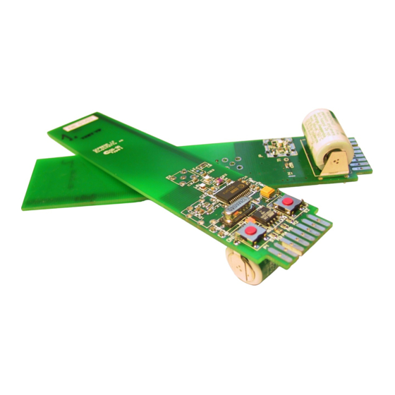
2 CC900DB Demonstration Board Before starting The CC900DB runs on a 3.6V Lithium battery. If the battery is not mounted and soldered to the board, insert the battery at the rear side of the board. Observe the LED. If the LED is turned on continuously, push the “ON” button. For proper operation the LED shall be pulsing with a period of approximately one second. -
Page 5: System Parameters
DEVICE 1 TX ACK DEVICE 2 LED (ACK) System parameters The system parameters used to generate the configuration data for the CC900DB is ® shown below. This is a printout from the SmartRF Studio software. System parameters: X-tal frequency: 12.000000 MHz X-tal accuracy: +/- 25 ppm RF frequency: 868.300 MHz... - Page 6 RX mode: Frame Addr/Data (hex) 006A 2B0B 4841 6033 8900 BA00 CB6C E072 TX mode: Frame Addr/Data (hex) 086A 2B0B 4841 608F 8914 BA00 CB6C E072 PD osc. on mode: Frame Addr/Data (hex) 186A 2B0B 4841 6033 8900 BA00 CB6C E072 PD osc.
-
Page 7: Micro-Controller Eeprom Mapping
RX Precharge mode: Frame AddrData (hex) 006A 2B0B 4841 6033 8900 BA00 CB6C E27A In this application we have decided to use RX Precharge, RX, TX and PD osc. off modes. Shown in bold in the listing above is the configuration data that is used, and stored in the micro-controller EEPROM. -
Page 8: Trouble-Shooting
Trouble-shooting If the module does not operate as described in this document, try the following. Problem Possible solution LED is continuously on Push the “ON” button once more. If this does not work, reset the micro-controller (see below). LED does not start blinking after “ON” is Check battery voltage. -
Page 9: Demonstration Board Software Description
Atmel. Sleep mode When the CC900DB is left inactive for approximately one minute the CC900 is set to power down mode, and the controller goes to “sleep”. The controller is awaked by an interrupt signal at INT1 (pin 6). -
Page 10: Data Packet Protocol
The ID is intended to be used for unique identification of different modules. However, this is not exploited in this software revision. All modules are addressed using the public address (0x00). The TYPE is used to separate between an original message (0x00) and an acknowledge (0x01). -
Page 11: Data Reception
Data reception The data reception algorithm is as follows: 1. Enter RX precharge mode, wait 2. Enter RX mode 3. The receiver shall receive synchronisation pattern (pre-amble) for some periods before it is allowed to detect SOF 4. Wait for SOF 5. -
Page 12: Demonstration Board Hardware Description
4 Demonstration Board hardware description RF-section The RF section consists of a CC900 chip with a few external components. The different parts of the circuit are explained below. 4.1.1 The loop filter The PLL loop filter contains the components C121-C123 and R121-R123. The ®... -
Page 13: Lna/Pa Matching
4.1.4 LNA/PA matching The input/output antenna matching network is optimised for 869.3 MHz operation. The ® component values were calculated in the SmartRF Studio software program, and consists of C51, L51 and L61. To compensate for layout parasitics the component values were tuned to optimise for 50 Ohm input impedance in receive mode, and maximum output power in transmit mode. -
Page 14: Controller Section
Controller section The controller section consists of an Atmel AVR ATtiny12L micro-controller with a few external components. 4.2.1 RC oscillator The internal RC oscillator is used as reference time base. The oscillator frequency is relatively independent of temperature and operating voltage. Its nominal frequency is 1.2 MHz, varying less than +/- 5% over the application temperature and supply voltage range. -
Page 15: In System Programming
4.2.3 In system programming ® By connecting the CC900DB to the CC900 evaluation board, SmartRF Studio can reprogram the micro-controller while in the circuit. Both the program code memory (flash) and the EEPROM can be reprogrammed. (an ATMEL AVR STK500 development board or an ATAVRISP in-circuit programmer can also be used). -
Page 16: Layout Sketches And Circuit Drawings
Layout sketches Drawing not to scale. SWRU064... - Page 17 SWRU064...
-
Page 18: Circuit Diagram
Circuit diagram SWRU064... -
Page 19: Bill Of Materials
Bill of materials CC900DB Reference Description Value Part Battery 3.6V LS14250 3PF, Lithium Thionyl Cloride, SAFT Capacitor, tantal C_3U3_TAN_B 3.3µF Capacitor 0603 33nF C_33N_0603_X7R_K_25 Capacitor 0603 220pF C_220P_0603_NP0_G_50 Capacitor 0603 C_1N0_0603_X7R_K_50 Capacitor 0603 33nF C_33N_0603_X7R_K_25 Capacitor 1206 C_1N0_0603_X7R_K_50 Capacitor 0603... -
Page 20: Using The Demonstrator Board As A Prototype Module
5 Using the Demonstrator Board as a prototype module The purpose of the Demonstrator Board is to show a simple transceiver module with battery supply and integrated PCB antenna. The demonstrator can be used “as is” for simple range and coverage measurements. But keep in mind that this module use only 0 dBm and a small rather ineffective antenna.
Need help?
Do you have a question about the CC900DB and is the answer not in the manual?
Questions and answers