Table of Contents
Advertisement
Quick Links
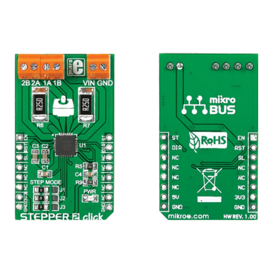
STEPPER 2
click
1. Introduction
Stepper
2
click
carries
an
A4988
microstepping motor driver along with
screw terminals for connecting an external
motor, as well as for bringing in an external
power supply. The output drive capacity of
the motor is up to 35V and ±2A. The board
communicates with the target MCU through
EN, RST, SL, ST and DIR pins (corresponding
to AN, RST, CS, PWM and INT pins of the
default mikroBUS™ configuration). Stepper
2 click has a 3.3V power supply but is also
compatible with 5V logic.
2. Soldering the headers
Before using your click board
™
, make sure
to solder 1x8 male headers to both left and
right side of the board. Two 1x8 male headers
are included with the board in the package.
2
Turn the board upside down so that
the bottom side is facing you upwards.
Place shorter pins of the header into the
appropriate soldering pads.
1
3
Turn the board upward again. Make sure
to align the headers so that they are
perpendicular to the board, then solder the
pins carefully.
3. Plugging the board in
Once you have soldered the headers your
board is ready to be placed into the desired
mikroBUS
socket. Make sure to align the cut
™
in the lower-right part of the board with the
markings on the silkscreen at the mikroBUS
socket. If all the pins are aligned
correctly, push the board all the
way into the socket.
4. Essential features
The A4988 chip is designed to drive bipolar
stepper motors in full-, half-, quarter-,
eight-, and sixteenth-step modes. No phase
sequence tables are required for operating
the driver – a single pulse through the STEP
input drives the motor one micro-step. A set
of three onboard jumpers (J1-J3) allow you
to switch between the different stepping
modes (a micro-stepping resolution truth
table is provided in the data sheet of the
chip. The DIR pin is for determining the
direction of rotation of the motor.
click
BOARD
™
www.mikroe.com
™
Stepper 2 click Manual v100
0 1 0 0 0 0 0 0 8 5 7 6 9
Advertisement
Table of Contents

Related Manuals for mikroElektronika STEPPER 2 click


Summary of Contents for mikroElektronika STEPPER 2 click
- Page 1 ™ to AN, RST, CS, PWM and INT pins of the socket. If all the pins are aligned Stepper 2 click Manual v100 default mikroBUS™ configuration). Stepper correctly, push the board all the 2 click has a 3.3V power supply but is also way into the socket.
- Page 2 WIDTH the present schematic are subject to change HEIGHT* at any time without notice. Stepper 2 click features three pairs of screw terminals. 2B, 2A, 1A and 1B are for 42.9 mm / 1690 mils Copyright © 2015 MikroElektronika. connecting the stepper motor, VIN and GND * without headers are for bringing an external power supply.
Need help?
Do you have a question about the STEPPER 2 click and is the answer not in the manual?
Questions and answers