
Related Manuals for Texas Instruments MSP-EXP430F5438


Summary of Contents for Texas Instruments MSP-EXP430F5438
- Page 1 MSP-EXP430F5438 Experimenter Board User's Guide Literature Number: SLAU263B January 2009 – Revised August 2009...
- Page 2 SLAU263B – January 2009 – Revised August 2009 Submit Documentation Feedback...
-
Page 3: Table Of Contents
................Software Installation and Debugging ..................Installing Code Composer Essentials ..................Working With the Example Software ........4.2.1 Working With the Example Software – MSP-EXP430F5438 Rev 0-02 ................Example Software – User Experience ......................User Experience ........................Main Menu ........................ - Page 4 www.ti.com ................... 5.3.5 Accelerometer Settings ........... Frequently Asked Questions, References, and Schematics ....................Frequently Asked Questions ........................References ........................Schematics Contents SLAU263B – January 2009 – Revised August 2009 Submit Documentation Feedback...
- Page 5 List of Figures ................MSP-EXP430F5438 Experimenter Board ................. Installing the MSP-EXP430F5438 USB Driver ....................... Functional Overview ....................Audio Output Signal Chain ....................Selecting a CCE Workspace ....................Opening the Existing Project ................Selecting Rev 0-02 in the Project Options ....................
- Page 6 All trademarks are the property of their respective owners. List of Tables SLAU263B – January 2009 – Revised August 2009 Submit Documentation Feedback...
-
Page 7: Preface
Information specific to the MSP-EXP430F5438 Experimenter Board can be found at http://focus.ti.com/docs/toolsw/folders/print/msp-exp430f5438.html. Support for the MSP430 device and the MSP-EXP430F5438 Experimenter Board is provided by the Texas Instruments Product Information Center (PIC). Contact information for the PIC can be found on the TI web site at www.ti.com. - Page 8 Read This First SLAU263B – January 2009 – Revised August 2009 Submit Documentation Feedback...
-
Page 9: Getting Started
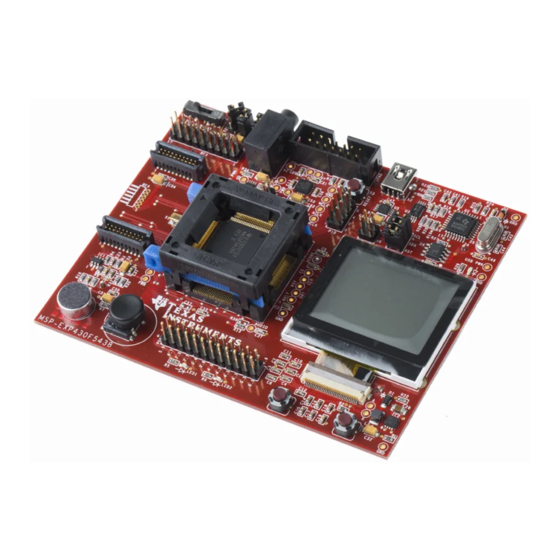
Getting Started MSP-EXP430F5438 Experimenter Board Introduction The MSP-EXP430F5438 Experimenter Board is an evaluation board meant to evaluate the capabilities of the MSP430F5438 family of microcontrollers. Built to complement the MSP430's high degree of mixed-signal integration, the Experimenter Board showcases external peripherals such a dot-matrix LCD, two-axis accelerometer, microphone, audio output, a serial USB connection and RF add-ons. -
Page 10: Tools Requirements
MSP430F5438. The JTAG programmer is connected to the MSP-EXP430F5438 Experimenter Board via the JTAG header located in the top center of the board. The MSP430F5438 utilizes the standard 4-wire JTAG connection. For more details on the installation and usage of the Flash Emulation Tool, see the MSP430 Flash Emulation Tool (FET) user's guide (SLAU157). -
Page 11: Hardware Installation
USB Driver Rev 0-03. This driver identifies the MSP-EXP430F5438 as a multi-port serial adapter. If you are using Rev 0-02 of the MSP-EXP430F5438, as identified on the back of the board, install the drivers located in the folder USB Driver Rev 0-02 instead. -
Page 12: Installing The Msp-Exp430F5438 Usb Driver
Hardware Installation www.ti.com Figure 2-1. Installing the MSP-EXP430F5438 USB Driver Hardware Installation SLAU263B – January 2009 – Revised August 2009 Submit Documentation Feedback... -
Page 13: Hardware Functional Overview
The interfaces to a 138x110 dot-matrix LCD, two-axis analog accelerometer, 5-directional joystick, 2 push buttons, and a complete analog signal chain from microphone to audio output jack enable the development of a variety of applications. The MSP-EXP430F5438 Experimenter Board also provides UART communication via the mini-USB connection, facilitating communication/data transfer with a PC host. -
Page 14: Functional Overview
Hardware Overview www.ti.com Figure 3-1. Functional Overview Hardware Functional Overview SLAU263B – January 2009 – Revised August 2009 Submit Documentation Feedback... -
Page 15: User Interfaces
Libraries that interface the MSP430 to these transceivers are available at www.ti.com/msp430 under Code Examples. The RF PWR jumper must be populated to provide power to the EM daughterboard. The following radio daughter cards are compatible with the MSP-EXP430F5438 Experimenter Board: •... -
Page 16: Ez430-Rf2500T Interface
3.3.2 eZ430-RF2500T Interface The eZ430-RF2500T module can be attached to the MSP-EXP430F5438 Experimenter Board in one of two ways – through an 18-pin connector (RF3) or a 6-pin connector (RF4). The pins on the eZ430-RF2500T headers are multiplexed with the pins on the CC-EM headers allowing the EZ430-RF2500T module to behave identically to a CC-EM daughterboard. -
Page 17: Audio Output Signal Chain
Figure 3-2. Audio Output Signal Chain Headers Port X.Y, P10, and RF3 The MSP-EXP430F5438 Experimenter Boards brings out three headers that can be used as additional connections to external hardware or for signal analysis during firmware development, Port X.Y, P10, and RF3. -
Page 18: Pin Mapping For Header P10
Headers Port X.Y, P10, and RF3 www.ti.com Table 3-4. Pin Mapping for Header P10 Pin Description Port Pin Port Pin Pin Description GPIO only P10.7 P10.6 GPIO only UCA3RXD / UCA3SOMI P10.5 P10.4 UCA3TXD / UCA3SIMO UCB3CLK / UCA3STE P10.3 P10.2 UCB3SOMI / UCB3SCL UCB3SIMO / UCB3SDA... -
Page 19: Software Installation And Debugging
To modify, compile, and debug the example code the following steps should be followed: 1. If you have not already done so, download the sample code from the MSP-EXP430F5438 tools page MSP-EXP430F5438 Example Software and USB Drivers (SLAC227). -
Page 20: Selecting A Cce Workspace
Build Project. To download and debug the code to the MSP430F5438 on the MSP-EXP430F5438 Experimenter Board, select Run > Debug Active Project. Note that the silicon must be properly inserted into the socket prior to selecting Run > Debug Active Project. -
Page 21: Working With The Example Software - Msp-Exp430F5438 Rev 0-02
4.2.1 Working With the Example Software – MSP-EXP430F5438 Rev 0-02 A revision number is printed on the back of the board. All of the MSP-EXP430F5438 boards purchased online show Rev 0-03. However, attendees of the MSP430 Advanced Technical Conference 2008 were given an MSP-EXP430F5438 Rev 0-02. -
Page 22: Changing Ti Build Settings
To build the project, right click on the project name in the C/C++ Projects window and select Build Project. To download and debug the code to the XMS430F5438 on the MSP-EXP430F5438 Experimenter Board, select Run > Debug Active Project or click on the bug icon in the CCE task bar. Note that the silicon must be properly inserted into the socket prior to selecting Run >... -
Page 23: Example Software - User Experience
This application displays a UART terminal to communicate with a host PC via USB cable at 57600 bps. Users can type in a terminal window to send characters to the LCD screen of the MSP-EXP430F5438 board. The board also sends out characters to the PC if there are any actions on the joystick or the push buttons. -
Page 24: Voice Recorder
Main Menu > Settings Menu www.ti.com 5.2.4 Voice Recorder The voice recorder allows users to record speech into the MSP430F5438 flash memory. Due to the large size of the flash (256 KB), users can store up to ~20 seconds of speech audio. •... -
Page 25: Accelerometer Settings
Main Menu > Settings Menu www.ti.com 5.3.5 Accelerometer Settings The user can recalibrate the accelerometer sensor by pressing Up while keeping the board flat and stationary. This screen also allows the user to specify whether the board will return from sleep mode if the board is tilted. - Page 26 Example Software – User Experience SLAU263B – January 2009 – Revised August 2009 Submit Documentation Feedback...
-
Page 27: Frequently Asked Questions, References, And Schematics
Frequently Asked Questions 1. Which devices can be programmed with the Experimenter Board? The MSP-EXP430F5438 board is designed specifically to demonstrate the MSP40F5438IPZ and the MSP430F5436IPZ silicon. Future MSP430 devices may be released which are also supported. 2. I have erased and reprogrammed the MSP430. Can I restore the factory-programmed firmware on the device? The software source files are available from http://www.ti.com/lit/zip/slac227. -
Page 28: References
(FET, USB, BATT) to see if the contrast looks better. The example software also allows you to increase or decrease the contrast settings. • Revision 0-03 of the MSP-EXP430F5438 board is incompatible with revision 0-02 (distributed in limited quantities for the Advanced Technical Conference 2008). The revision number can be found on the back of the Experimenter Board. -
Page 29: Schematics
Schematics www.ti.com Schematics The original Eagle CAD schematics and Gerber files are available for download (SLAC228). Figure 6-1. MSP430F5438 and Peripherals Schematic SLAU263B – January 2009 – Revised August 2009 Frequently Asked Questions, References, and Schematics Submit Documentation Feedback... -
Page 30: Usb To Uart Schematic
Schematics www.ti.com Figure 6-2. USB to UART Schematic Frequently Asked Questions, References, and Schematics SLAU263B – January 2009 – Revised August 2009 Submit Documentation Feedback... - Page 31 IMPORTANT NOTICE Texas Instruments Incorporated and its subsidiaries (TI) reserve the right to make corrections, modifications, enhancements, improvements, and other changes to its products and services at any time and to discontinue any product or service without notice. Customers should obtain the latest relevant information before placing orders and should verify that such information is current and complete.
Need help?
Do you have a question about the MSP-EXP430F5438 and is the answer not in the manual?
Questions and answers