Table of Contents
Advertisement
Quick Links
www.ti.com
EVM User's Guide: MCT8317EVM
MCT8317EVM Evaluation Module
This document is provided with the MCT8317 customer evaluation module (EVM) as a supplement to the
MCT8317x data sheet
(MCT8317 Three-Phase Sensorless-Trapezoidal BLDC Motor
details the hardware implementation of the EVM and how to setup and power the board.
Warnings..........................................................................................................................................................1
2
Introduction.............................................................................................................................................................................2
Guide....................................................................................................................................................................2
4.1 Hardware Connections Overview - MCT8317EVM...........................................................................................................
4.2 Connection Details.............................................................................................................................................................
4.3 MSP430FR2355 Microcontroller & User Interface.............................................................................................................
Lights..........................................................................................................................................................................7
4.5 User-Configurable Settings................................................................................................................................................
Setup.......................................................................................................................................................................9
Application....................................................................................................................................................9
6.1 Running the GUI................................................................................................................................................................
6.2 Offline Installer.................................................................................................................................................................
7 MSP430FR2355 Interface Firmware....................................................................................................................................
8
Schematics............................................................................................................................................................................12
8.1 Main Supply and Pi Filter.................................................................................................................................................
Interface.................................................................................................................................................13
8.3 USB to UART...................................................................................................................................................................
8.5 MSP430FR2355 MCU.....................................................................................................................................................
8.7 Status LEDs.....................................................................................................................................................................
8.8 Switches and Speed Input...............................................................................................................................................
9 Revision History...................................................................................................................................................................
Trademarks
™
LaunchPad
is a trademark of Texas Instruments.
All trademarks are the property of their respective owners.
1 Cautions and Warnings
Observe the following cautions and warnings as printed on the EVM board.
SLLU360 - DECEMBER 2022
Submit Document Feedback
Table of Contents
Overview.........................................................................................................................................3
MSP430FR2355.........................................................................................................11
Debug........................................................................................................................................14
HOT SURFACE:
Copyright © 2022 Texas Instruments Incorporated
ABSTRACT
Driver.........................................................................................15
Table of Contents
Driver). This User's Guide
Code...................................10
MCT8317EVM Evaluation Module
3
4
6
8
9
10
10
12
13
14
15
16
16
1
Advertisement
Table of Contents

Subscribe to Our Youtube Channel
Related Manuals for Texas Instruments MCT8317


Summary of Contents for Texas Instruments MCT8317
-
Page 1: Table Of Contents
Table of Contents EVM User's Guide: MCT8317EVM MCT8317EVM Evaluation Module ABSTRACT This document is provided with the MCT8317 customer evaluation module (EVM) as a supplement to the MCT8317x data sheet (MCT8317 Three-Phase Sensorless-Trapezoidal BLDC Motor Driver). This User's Guide details the hardware implementation of the EVM and how to setup and power the board. -
Page 2: Introduction
2 Introduction The MCT8317 is a 4.5-V to 20-V, 5-A peak integrated three-phase gate driver IC with sensorless trapezoidal for motor drive applications. It provides three accurately trimmed and temperature compensated half-bridge MOSFETS, gate drivers, charge pump, current sense amplifier, linear regulator for the external load and adjustable buck regulator. -
Page 3: Hardware And Software Overview
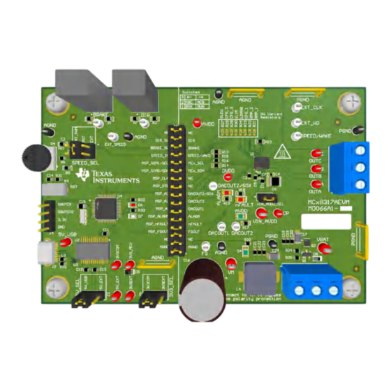
Optionally, use the GUI (as shown in Section 6) to monitor real-time speed of the motor, put the MCT8317 into a low-power sleep mode, and read status of the LEDs. Figure 3-1. Reference for Quick Start Guide 4 Hardware and Software Overview 4.1 Hardware Connections Overview –... -
Page 4: Connection Details
The three phases of the BLDC motor connect directly to the A, B, and C terminals of the screw terminal connector J8 provided on the MCT8317EVM. MCT8317EVM Evaluation Module SLLU360 – DECEMBER 2022 Submit Document Feedback Copyright © 2022 Texas Instruments Incorporated... - Page 5 500 mA and the 3.3 V from the FTDI chip is limit to 30 mA. If the user wishes to supply more current to these rails, they may use the 5V_SEL jumper J3 and 3V3_SEL jumper J5 to connect external power rails. SLLU360 – DECEMBER 2022 MCT8317EVM Evaluation Module Submit Document Feedback Copyright © 2022 Texas Instruments Incorporated...
-
Page 6: Msp430Fr2355 Microcontroller & User Interface
Finally, a shunt jumper bridge on the 32-pin connector J6 ties all signals between the microcontroller and MCT8317. These jumpers can be inserted or removed as needed in order to isolate the microcontroller from the gate driver. This allows for microcontroller signal debugging or using the MCT8317EVM as a standalone gate driver with an external microcontroller. -
Page 7: Led Lights
Color Description AVDD GREEN Lights up when AVDD is turned ON. Lights up when fault condition has occurred on MCT8317 nFAULT Lights up when alarm condition has occurred on MCT8317 ALARM Lights up when voltage is applied on VM. Green... -
Page 8: User-Configurable Settings
J1 = POT From Potentiometer R4 J1 = From internal PWM. INT_PWM PWM Duty cycle can be varied by rotating the POT R4. MCT8317EVM Evaluation Module SLLU360 – DECEMBER 2022 Submit Document Feedback Copyright © 2022 Texas Instruments Incorporated... -
Page 9: Hardware Setup
The MCT8317EVM includes a USB-UART interface, using a MSP430FR2355 microcontroller, that serves as a communication bridge between a host PC and the MCT8317 device for configuring various device settings and reading fault diagnostic information. A MCT8317A GUI is available to interface with and configure the MCT8317 using this communication interface. -
Page 10: Offline Installer
7 MSP430FR2355 Interface Firmware The MSP430FR2355 on the MCT8317EVM comes pre-programmed with the firmware necessary for communicating with the PC GUI and the MCT8317. In order to reprogram or flash custom code on the MSP430FR2355, you will need an external MSP430 LaunchPad ™... -
Page 11: Using The Ez-Fet To Program The Msp430Fr2355
Table 7-1. SPY-BI-Wire Connections Needed to Program MSP430FR2355 MSP430 LaunchPad ™ (eZ-FET Debug Probe Side) (J101) MCT8317EVM 4-pin SPI-by-Wire Header (J4) 3.3V SBWTDIO SBWTDIO SBWTCK SBWTCK SLLU360 – DECEMBER 2022 MCT8317EVM Evaluation Module Submit Document Feedback Copyright © 2022 Texas Instruments Incorporated... -
Page 12: Schematics
RPP PGND 330uF 100V 0.1uF 0.01uF 1000pF 1000pF 0.01uF 0.1uF 100V BUK9D 23-40EX MOTOR_OUT PGND PGND Figure 8-1. Main Supply and Pi Filter Schematic MCT8317EVM Evaluation Module SLLU360 – DECEMBER 2022 Submit Document Feedback Copyright © 2022 Texas Instruments Incorporated... -
Page 13: Connectors And Interface
Schematics 8.2 Connectors and Interface Figure 8-2. Connectors and Interface Schematic 8.3 USB to UART Figure 8-3. USB to UART Schematic SLLU360 – DECEMBER 2022 MCT8317EVM Evaluation Module Submit Document Feedback Copyright © 2022 Texas Instruments Incorporated... -
Page 14: Mcu Programming And Debug
Schematics www.ti.com 8.4 MCU Programming and Debug Figure 8-4. MCU Programming and Debug Schematic 8.5 MSP430FR2355 MCU Figure 8-5. MSP430FR2355 MCU Schematic MCT8317EVM Evaluation Module SLLU360 – DECEMBER 2022 Submit Document Feedback Copyright © 2022 Texas Instruments Incorporated... -
Page 15: Mct8317 3-Phase Sensorless Trapezoidal Integrated Driver
MCX_SCL PGND MCX_SDA AGND PGND PGND ALARM ALARM Therm al_Pad MCT8317A0IREER PGND AGND Figure 8-6. MCT8317 3-Phase Sensorless Trapezoidal Integrated Driver Schematic 8.7 Status LEDs AVDD LED nFAULT LED ALARM LED VM LED AVDD AVDD ALARM Green Green 1.00k 1.00k 2.2k... -
Page 16: Switches And Speed Input
9 Revision History NOTE: Page numbers for previous revisions may differ from page numbers in the current version. DATE REVISION NOTES December 2022 Initial Release MCT8317EVM Evaluation Module SLLU360 – DECEMBER 2022 Submit Document Feedback Copyright © 2022 Texas Instruments Incorporated... - Page 17 TI products. TI’s provision of these resources does not expand or otherwise alter TI’s applicable warranties or warranty disclaimers for TI products. TI objects to and rejects any additional or different terms you may have proposed. IMPORTANT NOTICE Mailing Address: Texas Instruments, Post Office Box 655303, Dallas, Texas 75265 Copyright © 2022, Texas Instruments Incorporated...
Need help?
Do you have a question about the MCT8317 and is the answer not in the manual?
Questions and answers