Table of Contents
Advertisement
Quick Links
NuMaker-M2354
NuMicro
®
Family
Based on Arm
®
Cortex
®
-M23
NuMaker-M2354
User Manual
Evaluation Board for NuMicro
®
M2354 Series
The information described in this document is the exclusive intellectual property of
Nuvoton Technology Corporation and shall not be reproduced without permission from Nuvoton.
Nuvoton is providing this document only for reference purposes of NuMicro microcontroller based system
design. Nuvoton assumes no responsibility for errors or omissions.
All data and specifications are subject to change without notice.
For additional information or questions, please contact: Nuvoton Technology Corporation.
www.nuvoton.com
Dec. 25, 2020
Page 1 of 54
Rev 1.00
Advertisement
Table of Contents

Related Manuals for Nuvoton NuMaker-M2354


Summary of Contents for Nuvoton NuMaker-M2354
- Page 1 The information described in this document is the exclusive intellectual property of Nuvoton Technology Corporation and shall not be reproduced without permission from Nuvoton. Nuvoton is providing this document only for reference purposes of NuMicro microcontroller based system design. Nuvoton assumes no responsibility for errors or omissions.
-
Page 2: Table Of Contents
Nu-Link2-Me ..................27 VCOM Switches ..................27 3.13.1 Status LEDs ..................27 3.13.2 Quick Start ................28 Toolchains Support ................28 Nuvoton Nu-Link Driver Installation ............28 BSP Firmware Download ..............30 Hardware Setup ................30 Dec. 25, 2020 Page 2 of 54 Rev 1.00... - Page 3 Keil MDK ..................... 32 4.6.1 IAR EWARM ..................35 4.6.2 NuEclipse .................... 37 4.6.3 NuMaker-M2354 Schematics ............43 Nu-Link2-Me ..................43 M2354 target Board .................44 USB 2.0 FS OTG ................45 Power Supply .................46 MCU Connector ................47 Arduino UNO Compatible Interface ............48 MicroSD Card ................49...
- Page 4 Figure 3-5 External Power Supply Sources on Nu-Link2-Me ............21 Figure 3-6 External Power Supply Sources on M2354 target board ..........22 Figure 3-7 Separate the Nu-Link2-Me from NuMaker-M2354 ............23 Figure 3-8 Wiring between Ammeter Connector and Ammeter ............. 24 Figure 3-9 LCD interface ........................
- Page 5 NuMaker-M2354 Figure 4-27 Debug Message on Serial Port Terminal Windows ............ 42 Figure 5-1 Nu-Link2-Me Circuit ...................... 43 Figure 5-2 M2354 Pin Assignment ....................44 Figure 5-3 USB 2.0 FS OTG Circuit ....................45 Figure 5-4 Power Circuit and Configurations ................. 46 Figure 5-5 MCU connector ......................
- Page 6 NuMaker-M2354 List of Tables Table 3-1 Extension Connectors ....................11 Table 3-2 M2354KJFAE Full-pin Extension Connectors and GPIO Function List ......16 Table 3-3 Arduino UNO Extension Connectors and M2354KJFAE Mapping GPIO List ....18 Table 3-4 Vin Power Source ......................19 Table 3-5 5V Power Sources ......................
-
Page 7: Overview
OVERVIEW The NuMaker-M2354 is an evaluation board for Nuvoton NuMicro M2354 microcontrollers. The NuMaker-M2354 consists of two parts, a M2354 target board and an on-board Nu-Link2-Me debugger and programmer. The NuMaker-M2354 is designed for secure evaluation, prototype development and validation with power consumption monitoring function. -
Page 8: Features
NuMaker-M2354 FEATURES NuMicro M2354KJFAE microcontroller with function compatible with: M2354LJFAE – M2354SJFAE – M2354KJFAE extension connectors Arduino UNO compatible extension connectors COM/SEG LCD with panel ETM (embedded trace macrocell) debug interface for instruction and data tracing of a processor ... -
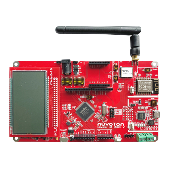
Page 9: Hardware Configuration
NuMaker-M2354 HARDWARE CONFIGURATION Front View Figure 3-1 Front View of NuMaker-M2354 Figure 3-1 shows the main components and connectors from the front side of NuMaker-M2354. The following lists components and connectors from the front view: Target Chip: M2354KJFAE (U1) ... -
Page 10: Rear View
NuMaker-M2354 Rear View Figure 3-2 shows the main components and connectors from the rear side of NuMaker-M2354. The following lists components and connectors from the rear view: Nu-Link2-Me MCUVCC Power Switch (ICEJPR1) – ICEVCC Power Switch (ICEJPR2) – ... -
Page 11: Extension Connectors
Table 3-1 Extension Connectors 3.3.1 Pin Assignment for Extension Connectors The NuMaker-M2354 provides the M2354 target chip on board and full pins extension connectors (JP6, JP7, JP8 and JP9). Figure 3-3 shows the M2354 extension connectors. Pin33 ~ Pin64 Pin1 ~ Pin32... - Page 12 NuMaker-M2354 M2354KJFAE Header Pin No. Function PB.5 / EADC0_CH5 / ACMP1_N / EBI_ADR0 / SD0_DAT3 / SPI1_MISO / I2C0_SCL / UART5_TXD JP6.1 / USCI1_CTL0 / SC0_CLK / I2S0_BCLK / EPWM0_CH0 / UART2_TXD / TM0 / INT0 PB.4 / EADC0_CH4 / ACMP1_P1 / EBI_ADR1 / SD0_DAT2 / SPI1_MOSI / I2C0_SDA / JP6.2...
- Page 13 NuMaker-M2354 M2354KJFAE Header Pin No. Function PF.4 / UART2_TXD / UART2_nRTS / EPWM0_CH1 / BPWM0_CH5 / X32_OUT JP6.32 PH.4 / EBI_ADR3 / SPI1_MISO / LCD_SEG36 JP8.1 PH.5 / EBI_ADR2 / SPI1_MOSI / LCD_SEG35 JP8.2 PH.6 / EBI_ADR1 / SPI1_CLK / LCD_SEG34 JP8.3...
- Page 14 NuMaker-M2354 M2354KJFAE Header Pin No. Function nRESET JP8.32 PF.0 / UART1_TXD / I2C1_SCL / UART0_TXD / BPWM1_CH0 / ICE_DAT JP7.1 PF.1 / UART1_RXD / I2C1_SDA / UART0_RXD / BPWM1_CH1 / ICE_CLK JP7.2 PD.9 / EBI_AD7 / I2C2_SCL / UART2_nCTS / LCD_COM7/SEG40 JP7.3...
- Page 15 NuMaker-M2354 M2354KJFAE Header Pin No. Function PE.6 / SD0_CLK / SPI3_I2SMCLK / SC0_nCD / USCI0_CTL0 / UART5_RXD / QEI1_A / JP9.2 EPWM0_CH1 / BPWM0_CH4 / LCD_SEG11 PE.5 / EBI_nRD / SD0_DAT3 / SPI3_SS / SC0_PWR / USCI0_CTL1 / QEI1_B / EPWM0_CH2 / JP9.3...
-
Page 16: Table 3-2 M2354Kjfae Full-Pin Extension Connectors And Gpio Function List
NuMaker-M2354 M2354KJFAE Header Pin No. Function PB.6 / EADC0_CH6 / EBI_nWRH / USCI1_DAT1 / UART1_RXD / EBI_nCS1 / BPWM1_CH5 / JP9.32 EPWM1_BRAKE1 / EPWM1_CH5 / INT4 / USB_VBUS_EN / ACMP1_O Table 3-2 M2354KJFAE Full-pin Extension Connectors and GPIO Function List Dec. -
Page 17: Arduino Uno Compatible Extension Connectors
NuMaker-M2354 3.3.2 Arduino UNO Compatible Extension Connectors Figure 3-4 shows the Arduino UNO compatible extension connectors. UART1_RXD BPWM0_CH3 PA.8 PB.6 ADC0_CH6 UART1_TXD BPWM0_CH2 PA.9 PB.7 ADC0_CH7 I2C0_SCL EPWM1_CH4 PC.1 PB.8 ADC0_CH8 I2C0_SDA EPWM1_CH5 PC.0 PB.9 ADC0_CH9 EPWM0_CH0 PE.7 PB.10 ADC0_CH10 EPWM0_CH1 PE.6... -
Page 18: Table 3-3 Arduino Uno Extension Connectors And M2354Kjfae Mapping Gpio List
NuMaker-M2354 NuMaker-M2354 NuMaker-M2354 Header Header Compatible to Compatible to GPIO Pin of M2354 GPIO Pin of M2354 Arduino UNO Arduino UNO NU4.1 PA.8 NU2.6 PB.6 NU4.2 PA.9 NU2.5 PB.7 NU4.3 PC.1 NU2.4 PB.8 NU4.4 PC.0 NU2.3 PB.9 NU4.5 PE.7 NU2.2 PB.10... -
Page 19: Power Supply Configuration
NuMaker-M2354 Power Supply Configuration The NuMaker-M2354 is able to adopt multiple power supply. External power source includes NU1 Vin (7 V to 12 V), V (depends on target chip operating voltage), and PC through USB connector. By using switches and voltage regulator, multiple power domains can be created on the NuMaker-M2354. -
Page 20: Power Sources
Table 3-9 presents the USB connectors. Connector Comment ICE USB connector on Nu-Link2-Me for power supply, debugging and ICEJ3 programming from PC. USB FS connector on NuMaker-M2354 for power supply. Table 3-9 USB Connectors 3.4.7 Power Switches Table 3-10 presents the power switches. Switch Comment Dec. -
Page 21: Power Supply Models
NuMaker-M2354 Configures the target chip operating voltage at 1.8 V / 3.3 V / 5 V. ICEJPR1 Note: M2354 operating voltage range is from 1.7 V to 3.6 V. Do not switch ICEJPR1 (MCUVCC) to 5 V. ICEJPR2 Configures the ICE chip operating voltage at 1.8 V / 3.3 V. -
Page 22: Figure 3-6 External Power Supply Sources On M2354 Target Board
3. Solder the resistor on ICEJPR2 (ICEVCC) depends on the ICE chip operating voltage. 4. Connect ICEJ3 to PC. 5. Connect the external power supply to JP13. To use Vin or J2 as external power supply source with Nu-Link2-Me separated from NuMaker-M2354, please follow the steps below: 1. Switch the SW4.2 to ON. -
Page 23: Figure 3-7 Separate The Nu-Link2-Me From Numaker-M2354
2. Separate the Nu-Link2-Me from NuMaker-M2354. 3. Connect the external power supply to JP13. Figure 3-7 Separate the Nu-Link2-Me from NuMaker-M2354 Table 3-12 presents all power models when supplying external power through the M2354 target board. The M2354 target board external power sources are highlighted in yellow. -
Page 24: External Reference Voltage Connector
NuMaker-M2354 External Reference Voltage Connector Table 3-14 presents the external reference voltage connector. Connector Comment VREF1 is used to easily connect to the external reference voltage pin of VREF1 the target chip. Remove the L11 ferrite bead before using it. -
Page 25: Swd / Etm Interface
The LED is connected to the target chip PD.2 and PD.3. ICES0, ICES1, ICES2 Nu-Link2-Me status LED. and ICES3 Table 3-16 LEDs Wi-Fi Module (ESP-12) U10: Wi-Fi Module ESP-12 on the NuMaker-M2354 board for application use. NuMaker- ESP-12 Description M2354 UART4_RXD... -
Page 26: Htn-Lcd Panel
NuMaker-M2354 HTN-LCD Panel The NuMaker-M2354 equip with a COM/SEG LCD interface which can connect to LCD panel. JLCD_1: 8 COM / 40 SEG LCD connective interface. JLCD_2: LCD Panel (HTN-3.3V) Figure 3-9 LCD interface Dec. 25, 2020 Page 26 of 54... -
Page 27: Nu-Link2-Me
NuMaker-M2354 Nu-Link2-Me The Nu-Link2-Me is an attached on-board debugger and programmer. The Nu-Link2-Me supports on- chip debugging, online and off-line ICP programming through SWD interface. The Nu-Link2-Me also supports virtual COM port (VCOM) for printing debug messages on PC. Besides, the programming status can be shown on the built-in LEDs. -
Page 28: Quick Start
KEIL MDK Nuvoton edition M0/M23 IAR EWARM NuEclipse (GCC)(Windows) NuEclipse (GCC)(Linux) Nuvoton Nu-Link Driver Installation Download and install the latest Nuvoton Nu-Link Driver. Download and install Nu-Link_Keil_Driver when using Keil MDK. Download and install Nu-Link_IAR_Driver when using IAR EWARM. -
Page 29: Figure 4-2 Nu-Link Usb Driver Installation
NuMaker-M2354 Figure 4-2 Nu-Link USB Driver Installation Dec. 25, 2020 Page 29 of 54 Rev 1.00... -
Page 30: Bsp Firmware Download
NuMaker-M2354 BSP Firmware Download Download and unzip the Board Support Package (BSP). Hardware Setup 1. Open the virtual COM (VCOM) function by changing Nu-Link2-Me VCOM Switch No. 1 and 2 to ON. Figure 4-3 Open VCOM Function 2. Connect the ICE USB connector shown in Figure 4-4 to the PC USB port through a USB cable. -
Page 31: Figure 4-5 Device Manger
NuMaker-M2354 Figure 4-5 Device Manger 4. Open a serial port terminal, PuTTY for example, to print out debug message. Set the speed to 115200. Figure 4-6 presents the PuTTY session setting. Figure 4-6 PuTTY Session Setting Dec. 25, 2020 Page 31 of 54... -
Page 32: Finding The Example Project
1. Double click the “Blinky.uvprojx” to open the project. 2. Make sure the debugger is “Nuvoton Nu-Link Debugger” as shown in Figure 4-8 and Figure 4-9. Note: If the dropdown menu in Figure 4-8 does not contain “Nuvoton Nu-Link Debugger” item, please rework section 4.2. -
Page 33: Figure 4-9 Programming Setting In Options Window
NuMaker-M2354 Figure 4-9 Programming Setting in Options Window 3. Rebuild all target files. After successfully compiling the project, download code to the Flash memory. Click “Start/Stop Debug Section” icon to enter debug mode. Figure 4-10 Compile and Download the Project Dec. -
Page 34: Figure 4-11 Keil Mdk Debug Mode
NuMaker-M2354 4. Figure 4-11 shows the debug mode under Keil MDK. Click “Run” and the debug message will be printed out as shown in Figure 4-12. User can debug the project under debug mode by checking source code, assembly language, peripherals’ registers, and setting breakpoint, step run, value monitor, etc. -
Page 35: Iar Ewarm
NuMaker-M2354 4.6.2 IAR EWARM This section provides steps to beginners on how to run a project by using IAR EWARM. 1. Double click the “Blinky.eww” to open the project. 2. Make sure the toolbar contain “Nu-Link” item as shown in Figure 4-13. -
Page 36: Figure 4-15 Iar Ewarm Debug Mode
NuMaker-M2354 4. Figure 4-15 shows the debug mode under IAR EWARN. Click “Go” and the debug message will be printed out as shown in Figure 4-16. The project can be debugged under debug mode by checking source code, assembly language, peripherals’ registers, and setting breakpoint, step run, value monitor, etc. -
Page 37: Nueclipse
NuMaker-M2354 4.6.3 NuEclipse This section provides steps to beginners on how to run a project by using NuEclipse. Please make sure the filenames and project folder path contain neither invalid character nor space. 1. Double-click NuEclipse.exe to open the toolchain. -
Page 38: Figure 4-19 Build Project
NuMaker-M2354 settings are the same as settings in Figure 4-20. Figure 4-19 Build Project Figure 4-20 Project Properties Settings 4. Click the “Blinky” project and build the project. Dec. 25, 2020 Page 38 of 54 Rev 1.00... -
Page 39: Figure 4-21 Build Project
NuMaker-M2354 Figure 4-21 Build Project 5. After the project is built, click the “Blinky” project and set the “Debug Configuration” as shown in Figure 4-22. Follow the settings presented in Figure 4-23, Figure 4-24 and Figure 4-25 to enter debug mode. -
Page 40: Figure 4-23 Main Tab Configuration
NuMaker-M2354 Note 1: Double click the “GDB Nuvoton Nu-Link Debugging” to create the subitem. Note 2: After the project is built, the “*.elf” file will be shown in “C/C++ Application” frame. Figure 4-23 Main Tab Configuration Figure 4-24 Debugger Tab Configuration Dec. -
Page 41: Figure 4-25 Startup Tab Configuration
NuMaker-M2354 Note 1: Please follow the settings highlighted in green triangles and configure other settings depending on the needs. Figure 4-25 Startup Tab Configuration Dec. 25, 2020 Page 41 of 54 Rev 1.00... -
Page 42: Figure 4-26 Nueclipse Debug Mode
NuMaker-M2354 6. Figure 4-26 shows the debug mode under NuEclipse. Click “Resume” and the debug message will be printed out as shown in Figure 4-27. User can debug the project under debug mode by checking source code, assembly language, peripherals’ registers, and setting breakpoint, step run, value monitor, etc. -
Page 43: Numaker-M2354 Schematics
NuMaker-M2354 NUMAKER-M2354 SCHEMATICS Nu-Link2-Me Figure 5-1 shows the Nu-Link2-Me circuit. The Nu-Link2-Me is a debugger and programmer that supports on-line programming and debugging through a SWD interface. 3.3V ICER1 Off-page Connector 200 1% USB_HS_CAP R0603 ICE5V ICEC1 ICEC2 ICE5V 0.1u... -
Page 44: M2354 Target Board
NuMaker-M2354 M2354 target Board Figure 5-2 shows the pin assignment of the M2354. RESET PB.5 PF.0 ICEDAT UNO Interface PB.4 PF.1 ICECLK PB.3 PD.9 COM7 Analog In PB.2 PD.8 COM6 PC.12 PC.5 COM5 PC.11 PC.4 COM4 PC.10 PC.3 COM3 P128 PB.6... -
Page 45: Usb 2.0 Fs Otg
NuMaker-M2354 USB 2.0 FS OTG Figure 5-3 shows the USB 2.0 FS OTG circuit on the NuMaker-M2354 board. USB1.1 OTG&HOST PA.15 USB_OTG_ID USB_ID PA.14 USB_D+ USB_D+ PA.13 USB_D- USB_D- PA.12 USB_VBUS USB_VBUS P117 PB.14 USB_VBUS_ST USB_VBUS_ST P116 PB.15 USB_VBUS_EN USB_PWR_EN... -
Page 46: Power Supply
NuMaker-M2354 Power Supply Figure 5-4 shows power configurations of NuMaker-M2354 board. POWER Off Page Power Connector USB_Host_5V USB_Host_5V USB_VBUS USB_VBUS VDD_MCU AVDD VREF NU1_VIN JP13_VCC NU1_VIN VBAT VBAT JP10 FERRITE BEAD FERRITE BEAD NU1_3VCC NU1_3VCC NU1_5VCC VSS (NC) VSS (NC) -
Page 47: Mcu Connector
NuMaker-M2354 MCU Connector Figure 5-5 shows the MCU Connector of JP6 to JP9. PB.5 PF.0 ICEDAT PB.4 PF.1 ICECLK PB.3 PD.9 COM7 PB.2 PD.8 COM6 PC.12 PC.5 COM5 PC.11 PC.4 COM4 PC.10 PC.3 COM3 PC.9 PC.2 COM2 PB.1 PC.1 COM1 PB.0... -
Page 48: Arduino Uno Compatible Interface
NuMaker-M2354 Arduino UNO Compatible Interface Figure 5-6 shows the Arduino UNO compatible interface of NU1 to NU5 connectors. PG.2 I2C1_SCL I2C_SCL PG.3 I2C1_SDA I2C_SDA UNO Interface P121 VREF VREF P122 AVSS Analog In RESET PA.2 SPI0_CLK MCU_RESET NU1_3VCC PA.1 SPI0_MISO... -
Page 49: Microsd Card
NuMaker-M2354 MicroSD Card Figure 5-7 shows the MicroSD Card circuit on the NuMaker-M2354 board. SD CARD 8P4R-10K SD_POWER 330R PB.0 SD0_CMD SD0_nCD R0603 PB.1 SD0_CLK SD0_DAT1 PB.5 SD0_DAT3 FERRITE BEAD SD0_DAT0 PB.4 SD0_DAT2 Green(LED0805) 8P4RA PB.3 SD0_DAT1 CB13 LED0805 PB.2... -
Page 50: Wi-Fi Module (Esp-12)
NuMaker-M2354 Wi-Fi Module (ESP-12) Figure 5-8 shows the Wi-Fi Module (ESP-12) for wireless application on the NuMaker-M2354 board. WIFI Off-page PC.6 UART4_RXD UTXD_ESP12 PC.7 UART4_TXD URXD_ESP12 PE.13 UART4_nRTS UCTS_ESP12 PC.8 UART4_nCTS URTS_ESP12 PD.12 IO0_ESP12 PC.13 RST_ESP12 ESP-12 10KR R0603 10KR... -
Page 51: Lcd Interface
NuMaker-M2354 LCD interface Figure 5-9 LCD interface Circuit shows the LCD connective interface and LCD panel for display application on the NuMaker-M2354 board. LCD Off-page JLCD_1 P[1:128] P[1:128] SEG1 P110 P111 SEG0 SEG3 P108 P109 SEG2 SEG5 P106 P107 SEG4... -
Page 52: Pcb Placement
NuMaker-M2354 PCB Placement Figure 5-10 Front Placement Figure 5-11 Rear Placement Dec. 25, 2020 Page 52 of 54 Rev 1.00... -
Page 53: Revision History
NuMaker-M2354 REVISION HISTORY Date Revision Description 2020.12.25 1.00 Initially issued. Dec. 25, 2020 Page 53 of 54 Rev 1.00... - Page 54 NuMaker-M2354 Important Notice Nuvoton Products are neither intended nor warranted for usage in systems or equipment, any malfunction or failure of which may cause loss of human life, bodily injury or severe property damage. Such applications are deemed, “Insecure Usage”.
Need help?
Do you have a question about the NuMaker-M2354 and is the answer not in the manual?
Questions and answers